Tuning up a littleBits oscillator

I’m starting to experiment with the littleBits oscillator and synth bits. I’d like to control the oscillators using an Arturia Keystep either through MIDI or through the Keystep’s control voltage (CV) and gate outputs.

Perusing the littleBits forum, I noticed several complaints about how difficult the oscillators are to tune. Setting the basic pitch is not a problem — just turn the PITCH knob. The issue is really intonation. Guitarists are very familiar with intonation, that is, being in tune along the fretboard. The keyboard equivalent is being in tune across the entire keyboard or a given range of keys.

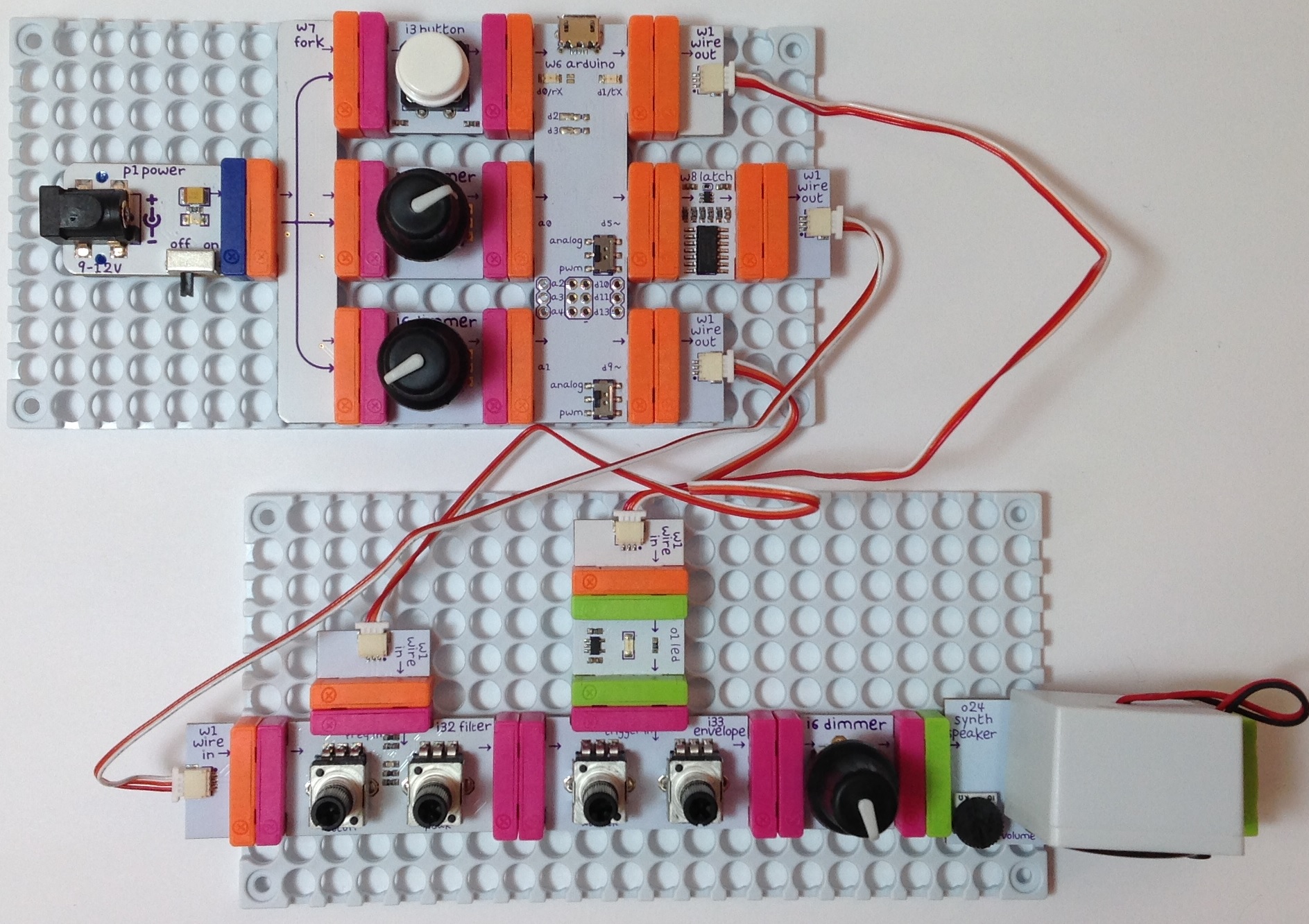
For my initial testing, I assembled a simple littleBits circuit:

Power -> MIDI module -> Oscillator -> Dimmer -> Synth Speaker

The littleBits MIDI module was connected to an Arturia Keystep and for comparison’s sake, a Korg MicroKORG. The MIDI module translates incoming MIDI note on and note off messages into littleBits-compatible CV. The Dimmer is the volume control. I find it much easier to set volume levels, etc. with a full-size pot instead of a trimmer. Also, I strongly recommend putting knobs on the oscillator PITCH pot. It is much easier to set the oscillator pitch accurately when a knob is installed. (Funny how the little things make a big difference.)

My first concern was the actual control voltage being sent to the oscillator. I pulled out my trusty multimeter and measured the Keystep’s pitch (CV) over a wide range of keys (notes). I also measured the CV generated by the littleBits w5 MIDI module. The voltages all look reasonable for 1 volt per octave CV, modulo the limited 3 digit precision of the multimeter. Two notes separated by an octave produced a one Volt difference as expected.

The Keystep generates CV from 0 Volts to 10 Volts. littleBits signals are limited to the range from 0 Volts to 5 Volts. Rather than tempt fate and drive the littleBits oscillator from the Keystep CV output, I decided to put a littleBits CV interface module on order. The CV interface scales CV to the littleBits range — whatever that means. Stay tuned.

The voltage for each note as produced by each CV source (Keystep CV vs. MIDI module) is not the same. For example, the Keystep generates 4.03 Volts for MIDI note C2 while the MIDI module generates 1.20 Volts. Relax. This isn’t a big deal as the basic pitch is easily set by the oscillator’s PITCH control. It’s all relative, man.

I used a Snark guitar tuner to set the pitch and to test intonation. The Snark is an inexpensive small tuner with a microphone input. I like the Snark because it shows the detected note (C, C#, D, etc.) and whether the note is flat or sharp. I don’t like the Snark because the clip-on thingy breaks off almost immediately! The clip-on thingy isn’t necessary for desktop testing, however.

I first tried setting the pitch and intonation by ear. This is where the MicroKORG was really handy. I sent the MicroKORG’s MIDI out to the MIDI-to-CV module and routed the MicroKORG’s audio output to the mixer feeding the studio monitors. I also patched the littleBits audio into the mixer, so I could easily dial up the MicroKorg audio as a pitch reference. Hit a single key on the MicroKORG and both the oscillator and MicroKORG attempt to play the same note. Adjust the PITCH and TUNE knobs appropriately.

The Snark tuner method is much better. The Snark’s display shows when things are sharp or flat. I recommend using a tuner like the Snark instead of matching pitch by ear.

At first I couldn’t get satisfactory intonation beyond a one octave range. This is disappointing and appears to be the place where most forum members gave up. I read the Korg littleBits Synth booklet paying particular attention to the tuning procedure on page 21. One of my biggest complaints about the littleBits system is the lack of detailed documentation and the Synth book was kind of sketchy about tuning and intonation. However, a light did turn on in my head.

I decided to turn the TUNE trimmer fully clockwise (thinking “OFF”). Then, I set the base pitch, i.e., the lowest pitch in the desired range. Next, I checked the highest note in the desired range — about two octaves. Natch, the intonation was bad, so I slowly turned the TUNE trimmer clockwise until the pitch of the highest note was correct. This disturbed the pitch of the lowest note and I had to find a balance between pitchiness at the low and high ends.

The result is fairly playable. I played the chromatic scale from lowest to highest and checked the Snark at each step. The intonation was acceptable.

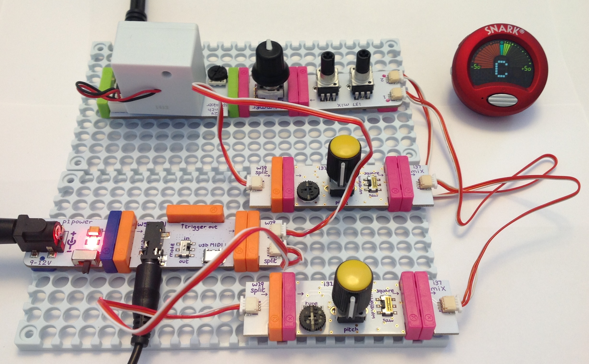
To make sure this procedure wasn’t a fluke, I tuned the second oscillator using the same method and got the same result. Finally, I wired up the MIDI module driving both oscillators and mixed the audio:

                             |-> Osc ->|
Power -> MIDI -> Split ->|         |-> Mix -> Dimmer -> Speaker
                             |-> Osc ->|

The pitches were danged close and the intonation of the individual oscillators matched quite well. I just needed to adjust the relative tuning to get a good phat sound.

Not bad for “cheap” $16 USD oscillators! It’s rather unfair to blame the oscillator design at this price. Plus, you did say that you want analog synthesis, right? We’ve gotten spoiled by decades of pitch-perfect digital synths. Making the tuning and intonation right is all part of the analog game.

One final thought. The littleBits CV signal driving the oscillators is somewhat under-documented. Voltage Control Lab have a nice analysis. They explain the littleBits OUT signal from the Korg SQ-1. They say that the CV signal plays two roles as a combined gate and pitch control. When the CV is asserted, i.e., the gate is high, the voltage level sets the pitch.

Here’s a more MIDI-centric interpretation. When a MIDI note is off, the CV signal is 0 Volts. The oscillator is silent at 0 Volts. When a MIDI note is on and held, the CV signal sets the pitch. When the MIDI note goes off, the CV signal returns to 0 Volts and silences the oscillator. This appears to be the behavior of the MIDI module (when it is in MIDI IN mode).

The Arduino combo organ is back

If you have a taste for cheesy 1960s combo organ sounds, I just posted the littleBits MIDI organ project. This project is an updated littleBits take on my old Combo Organ project. It uses the same “bottom octave generator” technique to squeeze five sample playback voices out of an Arduino.

Here’s an MP3 demo of the Farfisa voice and a demo of the Vox voice. I drove the MIDI organ from SONAR on a PC.

Here’s why you should prefer the littleBits version. The original project uses the MidiVox shield which is out of production. The littleBits version replaces the MidiVox with two breadboard-based circuits: a MIDI input interface and a Small Peripheral Interface (SPI) digital-to-analog converter (DAC). Easy to build and functionally equivalent. The new sketch incorporates improvements made to the Arduino SPI library and PROGMEM. The current SPI library uses a different convention for sending data to the DAC. PROGMEM is way different now; the old code won’t compile. The newer version of PROGMEM is stricter about typing and const.

The littleBits MIDI organ could form the basis of a sample playback synthesizer. Just replace the Farfisa and Vox waveforms with single cycle samples of your favorite synth or retro keyboard. Waveform space in PROGMEM is still tight, but hey, this is science. It’s supposed to be fun!

You’ll need to add a few headers to the littleBits Arduino module in order to use SPI. Here are some simple directions and tips:

Add SPI to littleBits Arduino Part 1
Add SPI to littleBits Arduino Part 2
Add SPI to littleBits Arduino Part 3

You’ll also find the SPI DAC and MIDI interface designs in parts 2 and 3, respectively.

While you’re at the littleBits site, check out f.j2’s Solina string synthesizer. Retro is bustin’ out all over!

I need to switch gears for a little while and be a musician again. So, I’ll be taking a short break from Arduino projects. More to come on the music side of things…

Add SPI to littleBits Arduino 3

At some point, you’ll want to go beyond the few inputs and outputs provided by the littleBits Arduino bitSnaps.

The stock littleBits Arduino module has twelve unpopulated signal pads:

  • Three analog inputs: A2, A3 and A4.
  • Three digital inputs/outputs: D10, D11 and D13.
  • Six ICSP signals: GND, MOSI/D16, VCC, RESET, SCK/D15, and MISO/D14.

Three of the ICSP pads can be used as ordinary digital inputs/outputs: D14, D15, D16. The same three ICSP pads also implement the Small Peripheral Interface (SPI): MOSI, MISO and SCK.

         GND ---O  O--- RESET
    MOSI/D16 ---O  O--- SCK/D15
         VCC ---O  O--- MISO/D14

The first article in this short series discusses the ICSP pads and how to solder a 2×3 header to the pads. The second article describes a circuit and code for a SPI-based digital-to-analog (DAC) converter using the Microchips MCP4921 integrated circuit.

The MCP4921 requires an active-low chip select (also known as “Slave Select”) signal to activate data communication with the SPI master (the Arduino). As described in part 2, I generated chip select through one of the bitSnap digital pins: D1, D5 or D9. D5 and D9 are buffered by a relatively slow-acting op amp. The op amp effectively imposes a delay on the chip select signal necessitating a long busy wait in the DAC’s interrupt routine. Pin D1 is not buffered, doesn’t require the busy wait and is faster.

Pin D1 itself does double duty. Depending upon its configuration, pin D1 functions as either an ordinary digital output or as the serial data output (TX). My latest project incorporates MIDI input and uses the Arduino MIDI library to parse and dispatch MIDI messages. After much experimentation and frustration, I determined that the MIDI library just doesn’t know how to keep its paws off pin D1 (TX). Even with MIDI THRU turned off (i.e., calling MIDI.turnThruOff()), the library seems to interfere with D1/TX. The interference disrupts communication with the MCP4921 DAC. Sending chip select by D5 or D9 is too slow, so it became time to populate the rest of the Arduino’s input and output pads.

We need two 1×3 pin headers to finish the job. I bought 1×3 pin headers from Jameco. In order to save time and money, you could just cut two 1×3 headers from a long header strip instead. Once again, I used a solderless breadboard as a jig to hold the headers in place while soldering. Here’s a tip (pun intended). Apply pressure to the side of each pin with the soldering tip; do not push down on the pin. If you push down, the pin may sneak down into the through-hole!

The 1×3 pin headers and the finished Arduino module are shown in the picture below. (As always, click on images for higher resolution.) With the 1×3 header pins soldered in place, I connected the MCP4921 chip select to Arduino pin D10 using a male-to-female jumper wire and changed the sketch to toggle D10.

When I was searching for the headers, I came across “breadboard friendly” 5-pin DIN sockets sold by Adafruit. Adafruit charges a pretty penny for these sockets, but they are well worth it. With the success of the SPI DAC implementation, I decided to build the MIDI input interface on a small solderless breadboard (picture below). These small 170 point breadboards are so inexpensive, there isn’t much need to build on a prototyping board.

Here are the schematic and broadboard layout for the MIDI input interface. Have fun!

Sing “Do Re Mi” using an Arduino SPI DAC

After a few months away from electronics, I dusted off the littleBits Arduino project that I completed way back in September. Just as I completed the project, we took a short vacation trip — just enough time away to break the creative flow and to procrastinate about a write-up.

The old-new project uses the Arduino SPI digital-to-analog converter which I sketched out in two earlier posts: How to add SPI to a littleBits Arduino and the Arduino SPI DAC design. The SPI DAC greatly improves audio quality over the el-cheapo PWM+filter approach. It adds a little extra hardware, but it’s worth it.

The SPI DAC project adds a 12-bit digital-to-analog converter (DAC) to the littleBits Arduino. The DAC is a Microchips Technology MCP4921. The design is fairly simple and could be whipped together by a novice. I built the circuit on a solderless breadboard in order to avoid soldering. You still need to solder a 2×3 header to the littleBits Arduino. Can’t avoid it unless littleBits decides to sell Arduino modules with pre-installed headers.

I wanted to make the project “kid friendly.” So, rather than geeking out with MIDI, synthesis, etc., the sketch sings a song in Solege (i.e., “Do, re, mi). The Arduino’s program memory (PROGMEM) holds the waveforms (samples) for the eight syllables of the C major scale. The song is represented in an array where each row of the array contains the pitch and duration of a note. The sketch steps through the song array and sings each note (a Solfege syllable). Check out the MP3 demo.

As you might guess, it took a fair bit of effort to fit the waveforms into 28K bytes of PROGMEM! For more information, read about the waveform development process.

I posted the full design and code on the littleBits web site. I want to move ahead to new projects and frontiers and I won’t be posting the detailed design here. I do want to use the SPI DAC in future projects.

While you’re at the littleBits site, please check out the Mini Pops Drumcomputer. This is a very nice update on the Lo-fi Beat Box project. The developer, f.j2, fabricated the low pass filter as a littleBits module using the littleBits Hardware Development Kit (HDK). He also added new waveforms. Great job!

Preparing audio waveforms for Arduino PROGMEM

The Arduino lo-fi Beat Box is kicking up some activity and comments on the littleBits site. (Follow this link to the Beat Box project page at littleBits.)

Two littleBits inventors have made considerable progress in suppressing the noisy buzz which seems to plague the el-cheapo lo-fi DAC design. I eventually gave up fighting the buzz and built a proper Small Peripheral Interface (SPI) DAC for the littleBits Arduino. See this page and this page for more information about the SPI DAC design. The main component is the Microchips MCP4921 12-bit SPI-compatible DAC. The audio output is much quieter.

I built a littleBits song player that sings a song in Do-Re-Mi Solfege. It uses the SPI DAC for conversion. Although I completed the project at the beginning of September 2016, I’m just now getting to a write-up for the littleBits site!

If you’re still hacking the Beat Box project, you should check out the ongoing discussion in the littleBits forum. Inventor alexpikkert built a rather spiffy passive low pass filter module using littleBits bitSnaps. I’m waaay too ham-handed for that kind of work, so I’m quite impressed by his implementation.

Another inventor, Frankje, would like to contribute some new drum waveforms. He needs more information about the drum waveforms and the process that I used to make them. So, here goes.

The drum waveforms (AKA “the samples”) are stored in the Arduino’s program memory (PROGMEM). PROGMEM is the non-volatile flash memory where the uploaded sketch resides. PROGMEM is quite big by Arduino standards. The Leonardo (ATmega32u4) has 1K byte EEPROM, 2.5K bytes SRAM (read/write RAM for variables) and 32K bytes of flash memory (PROGMEM). The bootloader uses 4KBytes of PROGMEM leaving 28K bytes for user code and data.

Notice that I said “and data.” The Arduino developers wisely give a sketch direct access to data stored in PROGMEM. A sketch reads data from PROGMEM using an access functions such as pgm_read_byte_near(). Thanks to PROGMEM, Arduino programmers can store a reasonably large amount of non-volatile data along with their code.

By now, if you are using a modern day musical instrument library (i.e., 10+ GBytes of sampled instruments), you’re shreiking in horror. I wanted to keep the Beat Box design small, simple and self-contained — no SD card or bulk flash memory. That means cramming all of the percussion samples into less than 28KBytes. Please remember, our sketch needs to fit into that 28K bytes, too.

Immediately, I chose a sampling rate and size that minimized space without sacrificing too much quality. The Beat Box sample format is 22,050Hz, signed 8-bit, mono. I tried a 10,025Hz sampling rate, but too much of the top end (high frequency brightness) was lost. The Arduino PWM conversion technique provides, at best, 8 or 9 bits of resolution, so its was easy to settle on 8-bit signed. Going mono cut waveform size in half. Stereo would require a second lo-fi DAC as well as upping memory consumption by a factor of two.

I started out sampling a TR-808 kit here and a TR-808 kit there. Nothing sounded as good as the TR-808 samples produced by Michael Fischer. Michael sampled a TR-808 back in September 1994 (!) and his sample set is excellent. He sampled each of the TR-808 voices over a range of knob (parameter) values. I went through the sample set, found the sounds which (to me) represent the 808, and chose sounds with the smallest WAV files from that representative subset.

Then, the torture began.

Michael’s samples are 44,100Hz, 16-bit, mono. So, I first down converted the chosen few waveforms to 22,050Hz, 8-bit, mono and I trimmed the samples as short as I could dare. My main audio editing tool is Sony Sound Forge Audio Studio, but any good audio editor could do the job. I’m most familiar with Sound Forge and can fly with it.

The next step is getting each waveform into a compilable, C-language source file. I converted each 22,050Hz, 8-bit mono WAV file to a RAW audio file. A RAW audio file does not have a header and contains only waveform samples. I wrote a program, raw2c.c, to convert a raw file to a C-language include file containing a formatted, C-language array that is initialized with the waveform samples. The program counts the number of samples and generates a #define for the array length.

Here is the source code for raw2c.c.

I also wrote a simple command script to batch convert all sixteen RAW files and to concatenate the individual include files into a single include file, waveforms.h.

Once I had the waveform.h file, I compiled the entire sketch to see if everything would fit into 28K bytes.

Then I repeated the trim, convert and compile process, again. And, again. And, again. You get the picture. I eventually had to mangle the waveforms. Truly a shame. The final cymbal sounds have only a brief shimmer of their true glory.

There you have it! I applied the same development process to the Do-Re-Mi waveforms although I started out with samples of my vocoded voice. Memory space requirements were even tighter (!) and I had to reduce the sampling rate to 11,025Hz.

Good luck, squeeze away and convert!

Copyright © 2017 Paul J. Drongowski

Add SPI to littleBits Arduino 2

Music makers working with littleBits Arduino will almost certainly want to add a high(er) resolution digital-to-analog converter (DAC) to their Arduino. Part 1 shows how to add an ICSP header to your littleBits Arduino module. The ICSP header is where you find the SPI signals — MISO, MOSI, and SCK — along with Vcc (+5 Volts) and ground. The ICSP header pin layout is:

         GND ---O  O--- RESET
    MOSI/D16 ---O  O--- SCK/D15
         VCC ---O  O--- MISO/D14

This is the layout when viewing the top of the Arduino module with the USB connector at the top (i.e., away from you, “north” on a map).

Now let’s take a look at a simple circuit using the Microchips MCP4921 12-bit DAC. (Click on images to get higher resolution.)

spi_dac_schematic

Three signals control the DAC: Slave Select (SS/Pin D9), Master Out Slave In (MOSI) and Serial Clock (SCK). Data is sent to the DAC through SPI’s bit serial protocol. First, SS is driven LOW, then 16 bits are sent one at a time to the DAC. SCK synchronizes the data bits sent via MOSI. The first byte consists of a 4-bit “command” and the top 4 bits of the 12-bit value to be converted. The second byte is the lower 8 bits of the value to be converted. After sending 16 bits, the SPI master drives SS HIGH. If you’re curious about all of the signaling details, please see the MCP4921 data sheet.

The rest of the DAC circuit consists of a voltage reference for the converter and a post-conversion (reconstruction) filter. The filter is a simple, one stage passive low pass filter with a 10,600Hz corner frequency.

I built the DAC circuit on a small solderless breadboard. Here’s the layout.

spi_dac_breadboard

I connected MOSI, SCK, +5V and ground to the appropriate ICSP pins on the Arduino module. Slave Select is sourced by Arduino pin D9. I connected a littleBits Proto module to D9 and routed the input signal to the breadboard. If you want to postprocess the DAC’s audio output with littleBits modules, then route the DAC output to the Proto module’s output snap. Be sure to remove the shorting block (jumper) between the middle two pins on the Proto module. This approach provides power and ground to the audio postprocessing modules connected to the output snap of the Proto module — an important side-benefit.

The choice of pin D9 for Slave Select was the beginning of a long, hard journey in debugging. To make a long story short, pins D5 and D9 are buffered and the output buffer introduces additional delay on the Slave Select signal. The delay is long enough such that the DAC does not see a low Slave Select signal before data bits start arriving.

Here’s the code that writes the DAC:

#define NOP asm volatile ("nop\n\t")
void busyWait(uint8_t count) { 
  for(uint8_t i = count; i > 0 ; i--) { NOP ; } 
}

void writeDac(int16_t dacValue) {
  byte data ;
  SPI.beginTransaction(SPISettings(20000000,MSBFIRST,SPI_MODE0)); 
  digitalWrite(SlaveSelect, LOW) ;
  busyWait(25) ;
  data = highByte(dacValue) ;
  data = 0x0F & data ;
  data = 0x30 | data ;
  SPI.transfer(data) ;
  data = lowByte(dacValue) ;
  SPI.transfer(data) ;
  digitalWrite(SlaveSelect, HIGH) ;
  SPI.endTransaction() ;
}

The busy wait effectively stops the sketch for a little while after driving Slave Select LOW. This gives the Slave Select more time to reach the DAC before the sketch transfers the first data byte to the DAC. If you use an unbuffered pin like D1, you don’t need the busy wait.

It took a long time to eliminate all of the other possible issues that could have caused a failure: bad solder joints, wiring mistakes, etc. Fortunately, I have a similar DAC — the MidiVox — which works correctly. I also tested the hardware with Arduino UNO where all digital pins are unbuffered. It was frustrating to get everything working with the UNO, but not the littleBits Arduino module! Persistence wins the day.

In closing, I want to warn developers who interface high speed logic to littleBits Arduino. Beware of the delay through those buffered outputs! The delay may be long enough to throw off critical timing.

Add SPI to the littleBits Arduino

As Moe Szyslak might say, “He ain’t pretty no more!”

Last time through, I mentioned that I wanted to add a SPI digital-to-analog converter (DAC) to the littleBits Arduino module. The Microchips MCP4921 is a good candidate. It is a 12-bit DAC which communicates via the Small Peripheral Interface (SPI) bus or “SPI.”

The littleBits Arduino module is essentially an Arduino Leonardo. As such, its SPI port is available through the module’s ICSP pads. (“ICSP” stands for “in-circuit serial programming,” by the way.) The ICSP pads are the group of pads (two rows of three pads) between the D5 and D9 bitSnaps.

I soldered a 2×3 vertical pin header to the ICSP pads using a very simple jig. The image below is a “before and after” picture. (Click images for higher resolution.) The jig is a solderless breadboard that holds the header in place. I pushed the header into the breadboard just enough to hold the header and then placed the Arduino module over the header and pressed down. The idea is to get the black base of the header in contact and properly aligned with the module printed circuit board (PCB). The blue strips of masking (painter’s) tape keep the assembly together. The “after” part of the image shows the module with the header soldered in place.

icsp_solder_after

The jig really makes the soldering job easy. I have used other methods like trying to tape the header pins in place, but this approach was a piece of cake and frustration free.

The image below shows the header, module and jig just before soldering. The picture also shows the 2×3 vertical pin header and a compatible 2×3 female header block. You could install the female header block instead. I went with the male header because most ICSP cables expect a male header on the PCB to be programmed.

icsp_solder_jig

I ordered the parts from Mouser Electronics. Mouser and Jameco are my usual “go to” sources for components and tools. Here are the part numbers:

  • Harwin M20-9980346 03+03 DIL VERTICAL male header 2.54mm
  • Harwin M20-7830342 03+03 DIL VERTICAL female header 2.54mm
  • BPS BB170-WH White 170 point solderless breadboard
  • BPS ZW-MF-20 ZIPWIRE Female-Male 20cm
  • BPS ZW-MM-20 ZIPWIRE Male-Male 20cm

The “2.54mm” refers to the pin spacing (AKA “0.1 inch”). The female header is $1.19 and the male header is $.24. Buy at least ten of each and the price goes down a little. The contacts are tin; gold is a little more expensive.

I plan to make (eventually) little PCB “hats” using the female header blocks. The idea is to build a small, single-purpose circuit that plug onto the ICSP header or littleBits Proto module header like a hat. This approach would eliminate point-to-point connections using jumper wires. I may experiment with this approach once I get the basic DAC circuit ironed out and tested.

I really like Busboard Prototype System (BPS) products. BPS has the most useful prototyping board patterns. They also have these nifty ZIPWIRE ribbon cables. The wires terminate with individual male pins or female receptacles. Let’s say you need to make six connections from the ICSP header to a solderless breadboard. Then tear off a group of six wires and associated terminations. Push the receptacles onto the male header and push the pins into the solderless breadboard. The individual wires are color-coded in order to make the correct point-to-point connections at both ends. I’ll use ZIPWIRE to connect the Arduino SPI port (ICSP) to a solderless breadboard with the SPI DAC circuit.

If you have a littleBits Arduino module and want to make the most of it, it’s time to break out the soldering iron. Best of luck!

Beat Box at littleBits!

Apologies in advance as I spend more time remembering to be a musician, not a technology blogger. I bought a few MIDI files during the last Yamaha Musicsoft sale and I’m massaging them into PJ-approved backing tracks. Plus, I’m learning about the joys of the key of D-flat!

I posted the Beat Box drum machine project to the littleBits invention site. The littleBits project format is more “step-by-step” than the document that I post on this site. The step-by-step directions should help anyone interested in building the Beat Box without diving into the details of the design. Of course, you can still check out the Beat Box design at this site, too. (MP3 Demo)

Just so you don’t think I’ve been totally idle, I tried adapting the code to sing “Do-Re-Mi” solfege. This involved recording and editing my voice. I used my old trick of singing through the Yamaha PSR-S950 vocoder in order to pitch correct my rocky intonation. I had to lower the sample rate to 11,025Hz in order fit all eight syllables into the very small Arduino program memory (PROGMEM). Unfortunately, I cannot get clear audio at 11,025Hz. There is this raucous buzz which cannot be eliminated through filtering. I suspect that the problem is in the PWM generation itself. The waveforms play back fine at 22,050Hz, sounding like chipmunk solfege.

After hitting that brick wall, I’ve decided to take a different approach which has better long term possibilities. I’ve ordered a handful of MCP4921 12-bit SPI DAC ICs and intend to try them with the littleBits Arduino module. The littleBits Arduino is a Leonardo where the SPI interface is the (unpopulated) ICSP pads. The new approach requires soldering, but it should be worth the effort. Stay tuned.

Still tempted by the Reface CP and YC. But, $400USD street? C’mon, Yamaha!

Arduino lo-fi beat box

Here’s another Arduino-based music project for ya — the Beat Box — a lo-fi, TR-808 drum machine. If you ever wanted to try your hand at DIY electronics, this one is a good starting point. Here is a short list of features:

  • 16 grungy, TR808-like rhythm instruments
  • Up to eight instruments per pattern
  • Up to five selectable patterns
  • Adjustable tempo (60 BPM to 188 BPM)
  • Full source code available including waveforms (samples)
  • Write and compile your own patterns, drum kits and waveforms
  • Built-in PWM signal generation into an external low pass filter
  • 22,050Hz, 8-bit signed, mono waveforms for true lo-fi grunge

The Beat Box uses the Arduino’s internal high resolution timer (TIMER1) to produce audio. The timer converts samples to a pulse-width modulated (PWM) bit stream which is sent into a simple low pass filter. The filter converts the PWM bit stream into an audio signal to be sent to a powered speaker, LINE IN, or what have you. This is absolutely the cheapest way to generate digital audio with an Arduino and it only requires four simple components, a solderless breadboard and a few jumper wires.

If you want to make assembly even easier, start with the littleBits Arduino Coding Kit, a Proto module and a Synth Speaker Module. I built the Beat Box using the littleBits Arduino Coding Hit and assembly was, literally, a snap.

The Beat Box source code includes drum waveforms and several classic drum patterns. With a 22,050Hz sampling rate and 8-bit samples, you get genuine lo-fi, bit-crunched TR-808 grunge. Purely optional, I added a littleBits synth Filter module and Delay module to the audio signal chain. Listen to the MP3 demo. In the demo, I sweep the filter frequency from low to open. At about 10 seconds in, you hear what is essentially the unfiltered sound of the Beat Box. Then, I increase the delay feedback level which adds echoes in time with the original pattern.

This pattern forever reminds me of riding the RTA #48 bus to work in Cleveland circa 1982.

Per standard operating procedure, I have provided the full design and source code.

Get your beat on! Build it now!

Add a filter and envelope to the tone sequencer

The tones produced by my littleBits tone sequencer are too basic. So, I decided to add a littleBits filter module and envelope module to spice things up. I built the Arduino part of the project on one mounting board and built the synthy part of the project on a separate board. Three wire modules connect the two subsystems together as shown in the picture below.

gatemodseq

Of course, since the whole thing is Arduino-based, it makes sense to drive filter modulation and envelope trigger (gate) from the Arduino. The trigger signal is turned on at the beginning of a note and is turned off at the end of a note. Nothing could be simpler.

The filter modulation signal is more fun. The dimmers connected to the Arduino control the attack and release time and the sustain level. Here is a simple diagram showing the shape of the filter modulation signal.

filter_mod_signal

One dimmer controls both the attack time and the release time. Close enough for rock and roll. I suppose that I could have added a third dimmer and controlled these times separately. A project for you perhaps?

Per standard operating procedure, I posted the design and code. The code is explained in detail. I also posted this project to the littleBits project site. The littleBits page has the source code, too, and has simple directions for building the project.

Have fun and keep on experimenting!