
The Yamaha PSR-S950 arranger workstation provides two different kind of Hammond B-3 organ voices:
- Regular, sampled organ voices
- Organ flute voices
An organ flute voice is similar to a true Hammond voice. It consists of nine independently controlled organ pipes, percussion, vibrato and rotary speaker effect. The S950 edit page displays nine drawbars which are adjusted using the up/down buttons just below the LCD display. Vibrato and rotary speaker speed are controlled using the buttons along the right and left hand sides of the LCD display. Percussion settings and overall organ volume are adjusted on a separate page.
Unfortunately, the buttons and drawbar display just don’t have the same feel as real physical drawbars. This situation sounds like the perfect application for one of the many MIDI controllers on the market. These controllers generally send MIDI continuous control (CC) messages to adjust drawbar values. However, Yamaha chose to control the drawbar settings through a single MIDI System Exclusive (SysEx) message that communicates all drawbar, percussion and volume settings at once. MIDI CC-based controllers don’t do SysEx and cannot control a PSR-S950 organ flute voice via SysEx.
This is just the kind of application where Arduino shines. The Arduino UNO has 14 digital I/O pins and 6 analog pins. We can easily attach a slide potentiometer (a “slider”) to an analog pin and sense the physical position of the slider based on the voltage at the pin. Nine analog pins would be better as one pin could be assigned to each single independent drawbar/slider. However, we can use multiple, button-selected operating modes to dynamically choose the mapping from physical slider to virtual drawbar. In this case, we are “functionally overloading” the sliders at the penalty of increased user interface complexity. We might also want to use sliders to control volume and vibrato, so functional overloading might give us a way to do this, too.
Hardware
The Arduino UNO is the second generation Arduino. Although more recent versions are available, I decided to use the UNO that I already had in order to keep project costs low. The UNO is mounted on a plastic Sparkfun base along with a small breadboard. This arrangement makes it easy to whip up and connect a MIDI output circuit to the Arduino. It also provides a stable base when the DangerShield is installed on top of the Arduino.
The Sparkfun DangerShield is a “jack of all trades” for small user interface experiments. I only made use of a subset of the DangerShield’s capabilities, in particular:
- Three long-throw slide potentiometers (for the drawbars),
- Three momentary push buttons (to select operating mode),
- Two LEDs (to indicate operating mode), and
- One seven segment display (to display drawbar value, etc.)
All of the interface elements are connected to the Arduino through the headers. This eliminates a lot of hand wiring and saves time. The DangerShield has female headers on top to which the MIDI output is connected.
There are a few drawbacks to the DangerShield in this application. First and most obvious, we don’t have nine sliders giving us one slider per drawbar. (Duh!) Next, the DangerShield is wider than the conventional width of an Arduino shield. The extra width is needed to accommodate the long slide pots and all of the spiffy components which Sparkfun thoughtfully included on the shield. Unfortunately, this means that the Arduino plus DangerShield combination cannot be mounted in a standard size Arduino enclosure such as the Arduino project enclosure (Arduino part number A000009).
The MIDI output circuit consists of a 5-pin DIN socket and two 220 ohm resistors. Pin 4 of the MIDI socket is pulled up to +5V through a 220 ohm current limiting resistor. Pin 2 is connected to ground. Pin 5 is connected to the Arduino’s TX pin (digital I/O pin 1). Here is the schematic:
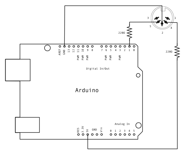
The TX pin also carries the serial out signal to the Arduino’s USB port, so we will need to be careful about coordinating debugging messages to the PC and binary MIDI messages. As Venkman said, “Don’t cross the streams.”
When everything is fully assembled, this is what you get:
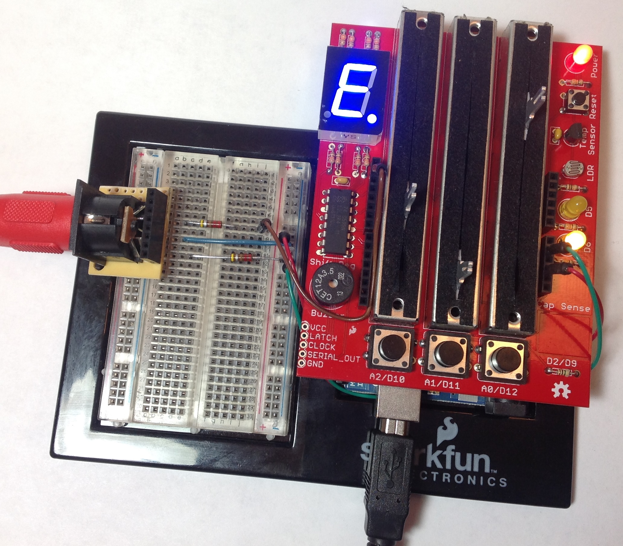
I put the 5-pin DIN socket on a breakout board of its own. This makes it easier to breadboard MIDI circuits. There is a red MIDI cable leading from the socket to the PSR-S950 keyboard. The Arduino UNO is dwarfed by the much larger DangerShield and is just barely visible in the picture. The whole she-bang is powered through the USB port. The project may also be powered by a 9V regulated adapter (center positive).
User interface
The user interface has three major modes:
- Drawbar mode: Adjusts the setting for each footage (16′, 8′, etc.)
- Effect mode: Adjusts organ volume, percussion and vibrato.
- Preset mode: Selects and loads one of 8 predefined organ registrations.
The preset mode is not yet implemented. The basic idea is to select and load one of eight predefined organ registrations where a registration is a complete combination of footages, percussion and vibrato. The eight settings are stored in the Arduino and are compiled into the program. No thought was given to user-controlled store and retrieve operations to support preset editing.
The DangerShield has three momentary pushbuttons (left, middle and right). Each button selects a major mode and up to three sub-modes (A, B, C). The button to major mode assignments are:
- Drawbar mode: Left button.
- Effect mode: Middle button.
- Preset mode: Right button.
A sub-mode is selected by repeatedly pressing the major mode button. The selected sub-mode is indicated by the two yellow LEDs that are located to the right of the sliders:
| Sub-mode | Top LED | Bottom LED |
|---|---|---|
| A | ON | OFF |
| B | OFF | ON |
| C | ON | ON |
Software must debounce the buttons.
In order to handle nine footages, the nine drawbar footages are separated into three groups with three footages per group. Each group of footages is assigned to a sub-mode as given by the following table:
| Sub-mode | Left | Middle | Right |
|---|---|---|---|
| A | 16′ | 5 1/3′ | 8′ |
| B | 4′ | 2 2/3′ | 2′ |
| C | 1 3/5′ | 1 1/3′ | 1′ |
The musician must first press the left button to select drawbar mode and group. Then, the musician moves one of the three sliders to change the assigned footage value. The drawbar value is shown in the seven segment display.
The Arduino analog inputs return a value in the range 0 to 1024. The software must map the raw analog input to the allowed drawbar value range of 0 to 8. This is accomplished by dividing the raw value by 114. A drawbar footage is changed when the
The sliders in effect mode control organ volume, percussion and vibrato. Each effect parameter is assigned to a slider according to sub-mode as shown below:
| Sub-mode | Left | Middle | Right |
|---|---|---|---|
| A | ROT Speed | PERC on/off | VIB on/off |
| B | PERC Volume | PERC Decay | PERC Harm |
| C | Organ Volume | VIB Depth | VIB Speed |
Some effect parameters are discrete, e.g., FAST or SLOW. Software must scale the raw analog input values to the appropriate internal range. The current effect value is shown in the seven segment display when a slider is moved and a value is changed.
The effect parameters are:
| Parameter | Values |
|---|---|
| ROT Speed | Fast, Slow |
| PERC Volume | Soft, Normal |
| PERC Decay | Fast, Slow |
| PERC Harm | Third, Second |
| Organ Volume | 0-8 |
| VIB Depth | 1-3 |
| VIB Speed | 0-8 which is mapped to 20:100 (decimal) |
Software must map these values to the appropriate MIDI messages and data values. The organ volume and percussion parameters are sent through the Yamaha organ flute SysEx message. Other parameters are sent through MIDI controller messages (CC and NRPN).
The following table shows slider functionality for each sub-mode in the preset major mode. The left slider selects and loads a preset organ registration. The preset is loaded simply by moving the slider to a different position. No confirmation is required. The selected preset number is indicated in the seven segment display.
| Sub-mode | Left | Middle | Right |
|---|---|---|---|
| A | Preset # | Future | Future |
| B | Future | Future | Future |
| C | Future | Future | Future |
In retrospect, this UI design forces the musician to think too much while playing. It is too difficult to choose a mode. A better approach is “one physical control for each parameter” as this would eliminate modes altogether. However, the non-model approach requires more physical controls, i.e., nine slide potentiometers, switches for percussion values, etc.
Software design and source code
The program follows the usual Arduino sketch structure:
- A function
setup()to initialize the serial interface and internal variables, and - A function
loop()that is called within the Arduino event loop to detect and handle slider changes and button presses.
The sketch (DrawbarTest.ino) keeps track of the current major mode and sub-mode. The program starts in drawbar mode, sub-mode A. The program maintains several global variables that keep track of the current drawbar, percussion, vibrato and volume settings. The settings are updated in response to slider changes depending upon the current major and sub operating mode.
Three utility functions display values in the seven segment display and show the current sub-mode:
- Function
displayDigit()displays a hexadecimal value in the seven segment display. - Function
displayChar()displays a character in the seven segment display. - Function
displayGroup()displays the current sub-mode in the two status LEDs.
The digit and character display functions make use of the table sevenSegmentDigits[] and several #defines to turn on the appropriate individual LEDs in the seven segment display, including the decimal point.
Six utility functions make and send MIDI messages:
- Function
makeOrganSysEx()maps internal organ settings to a Yamaha proprietary SysEx message. - Function
sendOrganSysEx()sends the organ settings SysEx message. - Function
sendMidiShort()sends a short 3-byte MIDI message on Channel 1. - Function
sendVibratoDepth()builds and sends a MIDI NRPN message to control vibrato depth. - Function
sendVibratoSpeed()builds and sends a MIDI NRPN message to control vibrato speed. - Function
sendDSPVarControl()builds and sends a SysEx message to control rotary speaker speed (i.e., “the DSP effect variation,” in Yamaha-speak).
Please see the Yamaha PSR-S950 Data List PDF document for MIDI message formats.
The sketch loop detects slider/button changes and dispatches internal program control based upon those changes. Thus, the control flow of the inner loop body is somewhat complicated. I added a simple tracing feature to the program to assist debugging. Tracing is controlled at compile time by the symbol TRACE. When TRACE is defined, the serial port speed is set to 9600 baud (instead of MIDI standard 31,250 baud) and the functions sendOrganSysEx() and sendMidiShort() send trace messages to the serial port instead of MIDI messages. Also, trace messages are sent from specific, key points in the program control flow. The trace messages are displayed in the serial port view within the Arduino IDE. The symbol TRACE must not be defined when compiling the code for MIDI output. You don’t want to send binary MIDI messages to the Arduino IDE and you don’t want to send textual trace messages to a MIDI keyboard!
Finally, here is a link to the source code.
Where it’s at
The PSR-S950 must be properly configured to respond to MIDI messages on Channel 1. I tested the DangerShield drawbars by selecting an organ flute voice for the RIGHT1 voice. Then, I changed the MIDI configuration such that RIGHT1 receives MIDI messages on Channel 1. Here is a step-by-step procedure:
- Call up the MIDI operation display. [FUNCTION] → [H] MIDI
- Select the “All parts” template from the Preset page. [A]
- Press the [8 ▼] (EDIT) button to call up the MIDI-related tabs.
- Use the TAB [◄][►] buttons to call up the MIDI Receive settings.
- Change the Part setting for Channel 1 to RIGHT1 (instead of SONG).
BTW, you’ll need to follow this simple configuration procedure if you use one of the Yamaha iPad apps to control RIGHT1 via Channel 1.
The sketch compiles and runs. Control flow is correct. Drawbar mode successfully controls the PSR-S950 virtual drawbars. The S950 responds to changes in percussion, but not organ volume. Overall, control using the Yamaha organ SysEx message is viable.
The sliders do not adjust vibrato depth and speed as expected. MIDI continuous control (CC) or SysEx messages may be needed instead of NRPN messages. First, I would try MIDI CC#76 and CC#77 to change the vibrato rate (speed) and depth, respectively. Failing that, I would try sending Yamaha XG SysEx messages for MULTI PART vibrato depth and speed.
There are Arduino boards that have more than 6 analog inputs. The Pro Mini supports 8 analog inputs and the Leonardo supports 12 analog inputs. The Leonardo looks like a good choice if you go the “one slider per drawbar” route.