
As promised, here is a review of the Mystic Circuits 0HP Envelope module. I won’t go through build details, etc., since I discussed these aspects of the 0HP line in my review of the Mystic Circuits 0HP 0ttenuator.
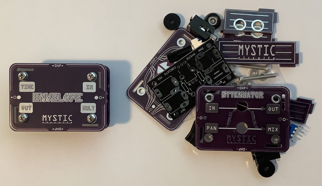
The 0HP modules all share the same micro form factor. The 0HP Envelope has four jacks:
- IN: Gate or audio input
- MULT: Duplicates the IN signal for patches
- TIME: Release time control voltage (CV) input
- OUT: Envelope output
Given a gate signal, the 0HP Envelope module generates a simple envelope. Given an audio signal, the Envelope module is an envelope follower, i.e., it generates an envelope which tracks the audio amplitude.
Schematic
Mystic Circuits have not posted a schematic for the 0HP Envelope. So, I drew one up. [Click images to enlarge.]
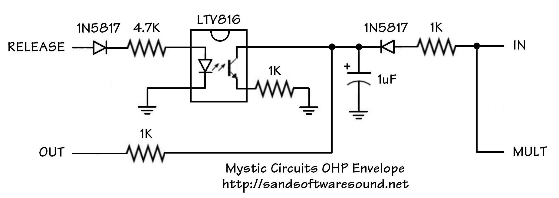
The 1uF capacitor is key to understanding the Envelope’s operation. The IN signal charges the 1uF capacitor while the phototransistor in the optoisolator (KTV816) discharges the capacitor to ground. The charge on the capacitor determines the OUT voltage. If you put audio into the Envelope, the capacitor smooths out the audio, leaving only the amplitude envelope.
The (release) TIME signal controls the brightness of the LED in the optoisolator. The brightness then controls the gate of the phototransistor. When the LED is brighter, the gate turns ON harder, more current flows, and the capacitor discharges faster.
Initial use
I had hoped to use the 0HP Envelope as an envelope follower such that I could process audio through the littleBits Filter module. Short story: A minor fail, but not the fault of the 0HP Envelope.
I connected the output of a Yamaha PSS-A50 to the audio input of the littleBits Filter. I sent the audio — in parallel — to the IN jack of the 0HP Envelope. No joy, or at least, not much happiness. I could not discern an audible difference in the filter cut-off sweep.
This minor failure motivated a few quick experiments to better understand the 0HP Envelope.
Oscilloscope: Audio envelope follower
When puzzled, measure!
Keeping the PSS-A50 as my audio source, I monitored the incoming audio signal and outgoing envelope using a Gabotronics USB oscilloscope.
The 0HP Envelope is, essentially, a passive device. It doesn’t require power and it doesn’t have any active electronics to amplify the incoming audio (or gate) signal. The phototransistor in the optoisolator acts like a variable resistor. Thus, what comes out of the envelope depends on what goes into it.
I immediately had to crank the oscilloscope gain to compensate for the small peak-to-peak audio signal going into the 0HP Envelope. The audio signal from the PSS-A50 does not have much voltage swing. The incoming signal limits the sweep of the outgoing envelope signal.
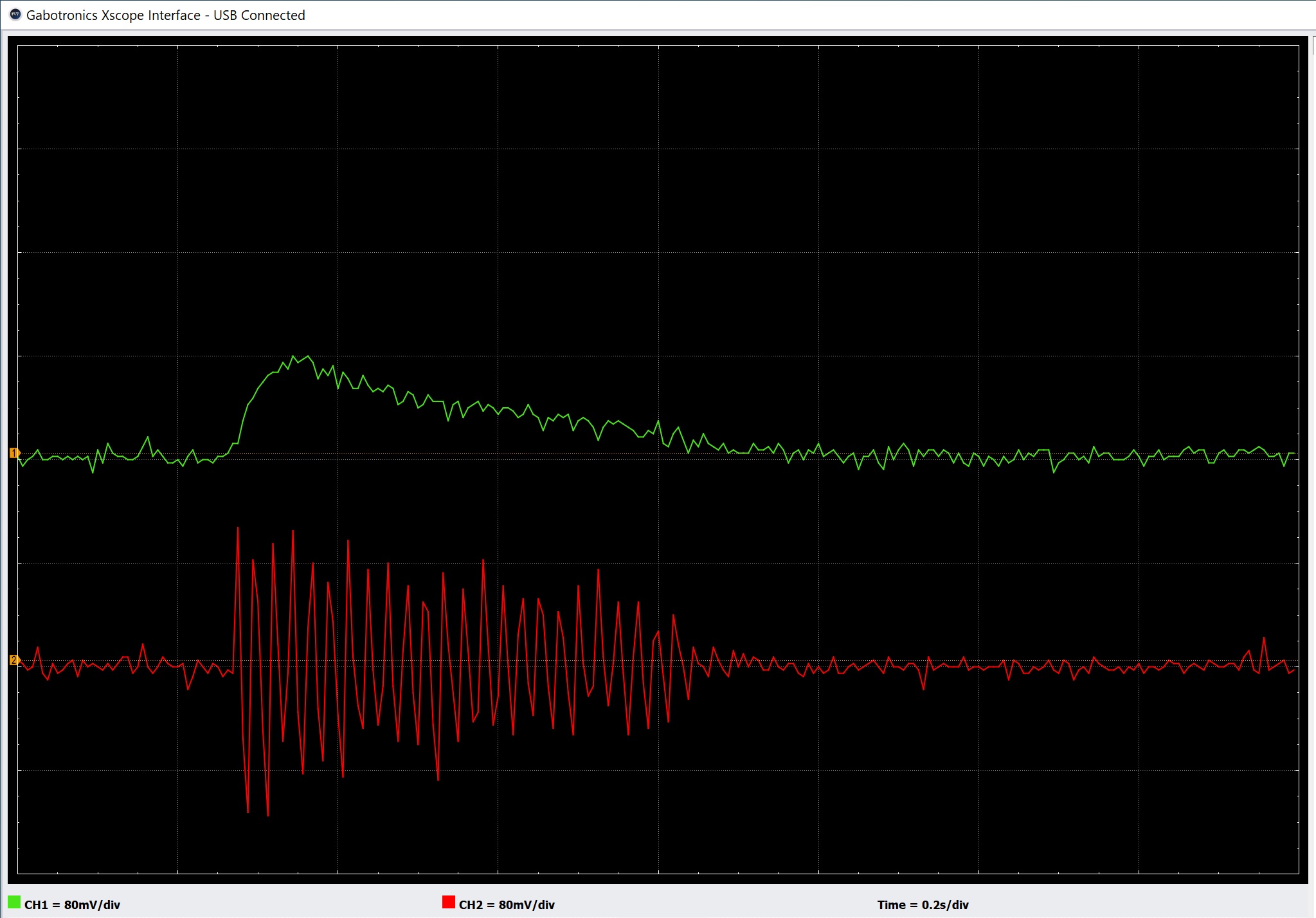
The oscilloscope traces above are a short piano note and the envelope produced by the 0HP Envelope module. Please note the voltage per grid unit; it’s very small. The small peak-to-peak audio signal does not produce a very large envelope voltage swing. The small swing was probably not enough to produce an audible filter cut-off sweep in the littleBits case.
The oscilloscope traces below are an oboe note and its envelope.
The traces look quite noisy thanks to the high oscilloscope gain. I suspect that some noise is to due to the crummy USB ground from the PC.
Oscilloscope: Gated envelope
To verify my hypothesis concerning signal level in affecting signal level out, I connected the Arturia Keystep Gate output to the 0HP Envelope module and monitored both the gate and envelope signals with the oscilloscope.
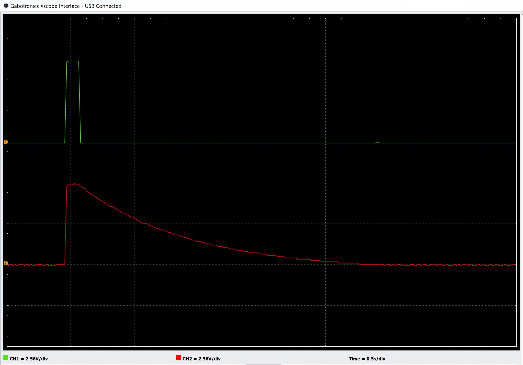
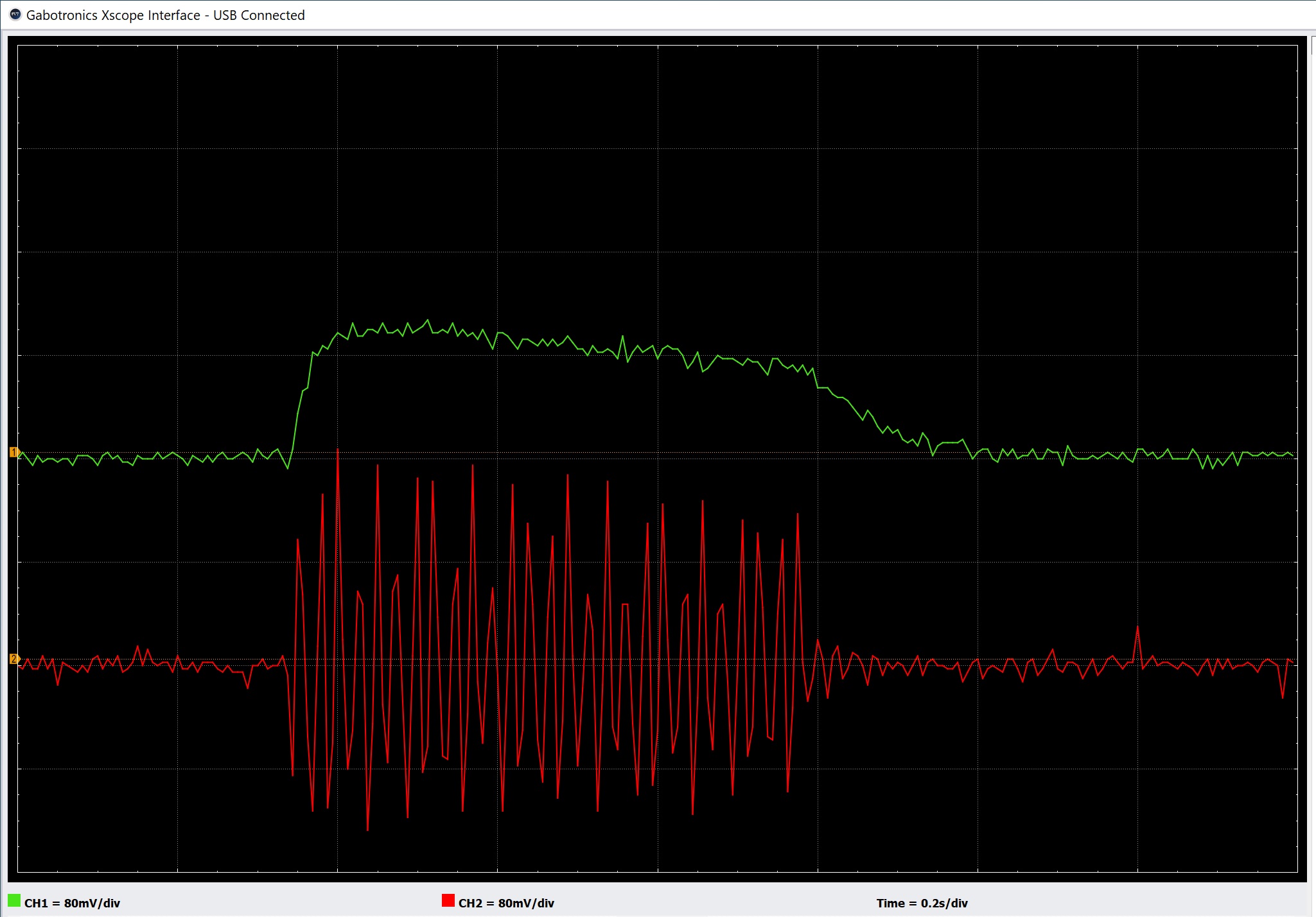
As expected, I needed to adjust the oscilloscope gain down to accommodate the relatively higher gate voltage. Given a strong gate signal, the envelope swing is much wider as shown in the oscilloscope traces above.
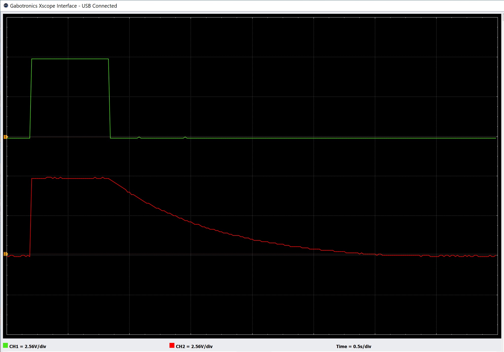
The 0HP Envelope stays high while gate is asserted. The example below shows the envelope produced by a longer note. When the TIME input is unused (0 Volts), the release time is rather long. You will most likely need to adjust the release time in practice unless you want a long release!
Summary
Overall, the 0HP Envelope does what Mystic says. It’s a reasonable envelope generator (or follower) as long as you understand its behavior: big signal in, big signal out; small signal in, small signal out.
Here are further notes taken from the Mystic Circuits video about the 0HP Envelope.
When driven with a Gate, the Envelope will stay ON while the Gate is high. Then it will slowly release to zero when the Gate goes low.
Release time is controlled by the RELEASE control voltage (CV) input. With no control voltage going into RELEASE, the Envelope release time is at its longest. Release time decreases as a positive CV is applied. When driven with audio, the Envelope will give you a voltage which is proportional to the amplitude of the incoming audio. Sensitivity is controlled by the RELEASE CV input. When driven with a variable voltage, the Envelope will glide when the input voltage falls. It will increase quickly when the input voltage rises. Glide time is controlled by the RELEASE CV input. This only works on positive voltages.
The Envelope module has an on-board MULT to the input which allows chaining of multiple units. This is useful when you want to use an active envelope generator to produce more complex shapes and use the 0HP to produce simpler shapes. You can also route incoming audio back into your patch.
Copyright © 2021 Paul J. Drongowski