
I discovered Mystic Circuits while browsing Patchwerks. Mystic Circuits make and distribute a line of analog synthesis modules including its “0HP” micro-modules. Time to take a look.
But, first. Patchwerks? Patchwerks was a great little find, too, and a synthesizer lifeline during the pandemic. Patchwerks has a small Seattle-based brick-and-mortar retail store as well as its Web store. I have yet to step into their physical store, but I have ordered a number of small boards and toys on-line. Each time, their fulfillment has been fantastic: good packaging, same day shipping and quite frequently, over-night delivery, thanks to our Seattle metro locations. Watch for their seasonal sales. Highly recommended!
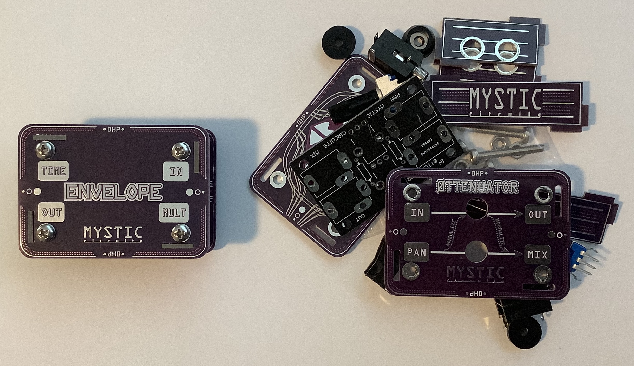
The 0H modules get their name because they don’t take up space in your modular rack. Each module implements one or more utility and synthesis functions that don’t require a rack slot. Just patch ’em in. Mystic Circuits offer 0HP modules both fully assembled and in kit form. Initially, I was searching for an envelope follower block and in the course of that search, I discovered the entire 0HP product line. I bought the 0HP Envelope module (fully assembled $36USD) and the 0ttenuator module (kit form $18USD). I focus on the 0ttentuator in today’s post.
Mystic Circuits 0HP 0ttenuator
The 0HP 0ttenuator is one of those modules that you can’t live without. It performs four functions:
- Single passive signal attenuator
- Dual, independent passive signal attenuators
- Two input passive mixer
- One-to-two signal splitter
I can’t count the number of times when I needed a simple signal attenuator (e.g., knocking a headphone level down to LINE), or a 2-input mono mixer. The 0ttenuator does the job and then some.
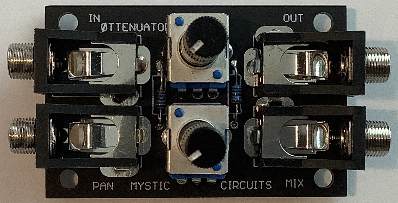
Even though Mystic Circuits call it the “simplest kit,” I wouldn’t recommend it for beginners. The resistor pads are really dinky and it would be easy to make a solder bridge to other, larger pads. You need a really good soldering tip to nail it. I suggest checking your work with a magnifying glass. Further, Mystic don’t identify the resistor values (or color codes). The resistors are so small, I can’t accurately read the color bars! Whip out a digital meter and the resistors measure as 22K ohms. The potentiometers (B104) are 100K ohms.
If I have to ding Mytic Circuits, I find their documentation to be thin and sketchy. Useful information is buried in video, including build and operating instructions. Nothing is written down. Frankly, I don’t have time to watch a video when I can read bullet points in a few seconds. Although Mystic provide Eagle “sch” files on their github site, most people aren’t set up to display Eagle. I ran the sch file through schematics.io and captured the rendering (below).
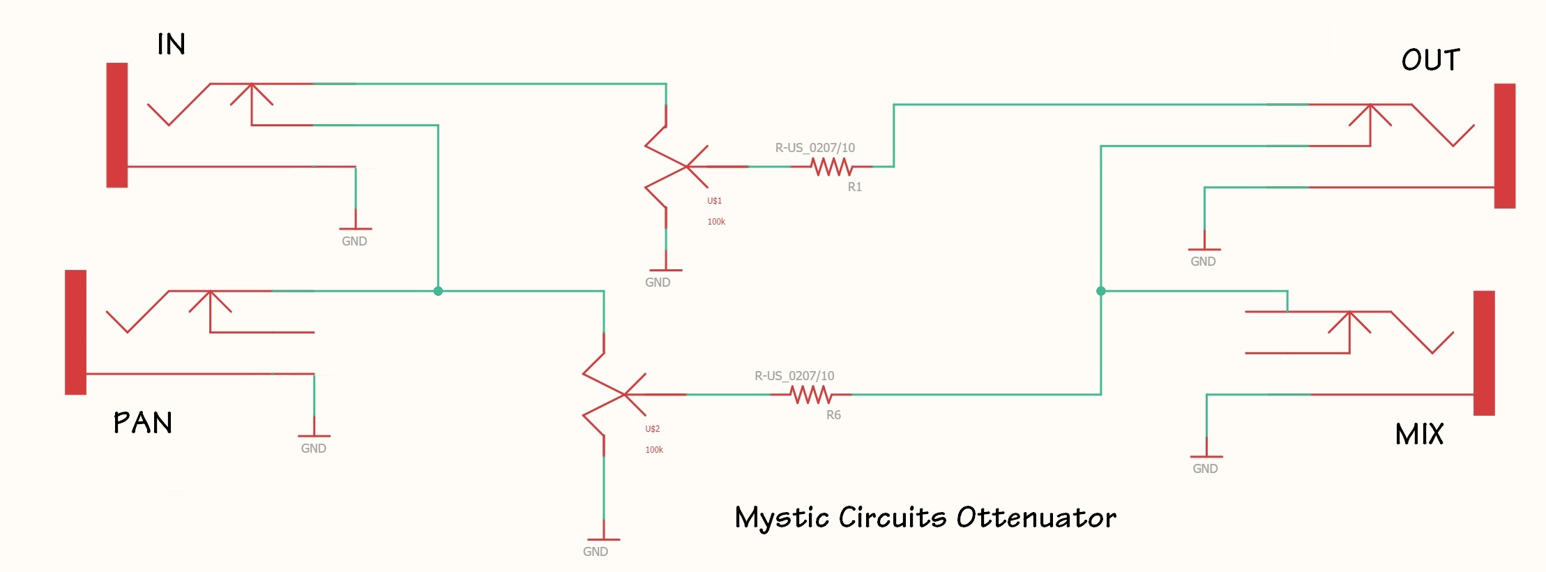
Hey, I’ve seen this circuit somewhere before! Nonetheless, it’s a very flexible design and the 0HP module is well-made. Operation depends upon the switched input jacks which configure the circuit for attenuation, mixing and splitting.
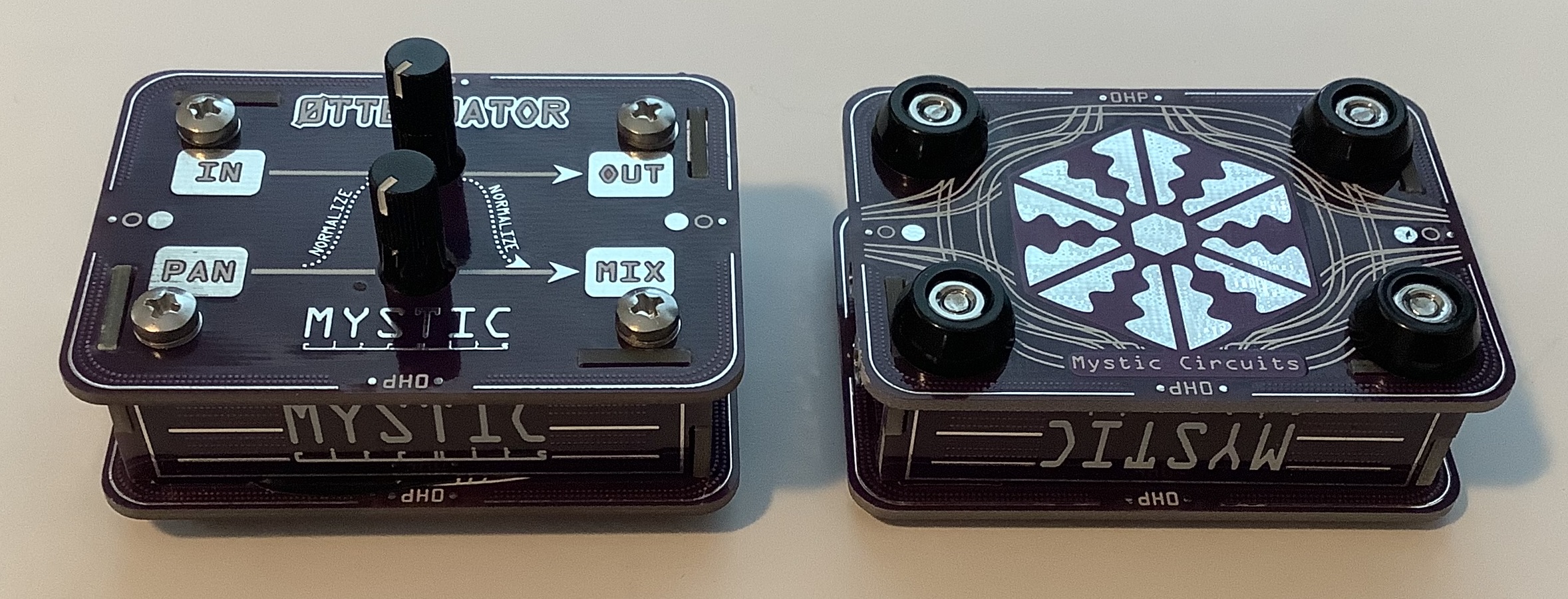
I’m glad that I purchased a fully assembled Envelope module along with the 0ttentuator kit. The fully assembled module showed me how to assemble the case. Again, the Mystic Circuits site does not have instructions for assembling the new 0HP cases. The video build instructions show the old plexiglass covers and spacers, not the new PCB-ish case. That’s the drawback of putting everything in videos; if the product changes, it’s a pain to revise the existing videos to reflect product changes.
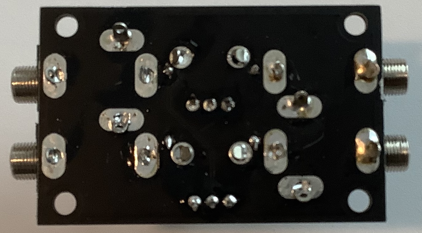
The final niggle has to do with the metallic graphic design on the case bottom. I fear it will make unwanted contact with the bottom of the printed circuit board (PCB). I put a thin layer of electrical tape over the inner surface of the bottom case cover. (The design is etched onto both sides of the case bottom.)
If you buy a 0HP 0ttentuator module — and I recommend it — here are the missing operating instructions:
- To use one attenuator:
- Plug incoming signal into IN jack
- Plug outgoing signal into OUT jack
- Turn knob to change signal level
- To send an incoming signal to two places:
- Plug incoming signal into PAN jack
- Plug one outgoing lead into the OUT jack
- Plug the other outgoing lead into the MIX jack
- Use knobs to set outgoing levels
- To mix two signals together:
- Plug one incoming signal into the IN jack
- Plug the other incoming signal into the PAN jack
- Plug the outgoing lead into the MIX jack
- Use knobs to set the outgoing level
- To use each attenuator separately:
- Plug first signal into the IN jack and the corresponding output lead into the OUT jack
- Plug second signal into the PAN jack and the corresponding output lead into the MIX jack
- Use knobs to set levels for each separate signal
Mystic Circuits 0HP Envelope
I want to test the 0HP Envelope with a littleBits Filter. Given time constraints, I’ll address that subject in a future blog. In the meantime, here is a little more information about the 0HP Envelope.
Here is a description of the 0HP Envelope, paraphrased from the Mystic Circuits video.
When driven with a Gate, the Envelope will stay ON while the Gate is high. Then it will slowly release to zero when the Gate goes low. Release time is controlled by the RELEASE control voltage (CV) input. With no control voltage going into RELEASE, the Envelope release time is at its longest. Release time decreases as a positive CV is applied.
When driven with audio, the Envelope will give you a voltage which is proportional to the amplitude of the incoming audio. Sensitivity is controlled by the RELEASE CV input. When driven with a variable voltage, the Envelope will glide when the input voltage falls. It will increase quickly when the input voltage rises. Glide time is controlled by the RELEASE CV input. This only works on positive voltages.
The Envelope module has an on-board MULT to the input which allows chaining of multiple units. This is useful when you want to use an active envelope generator to produce more complex shapes and use the 0HP to produce simpler shapes. You can also route incoming audio back into your patch.
Unfortunately, the Mystic Circuits github area does not have an Eagle schematic. So, I drew one (shown below). Hope I got it right!
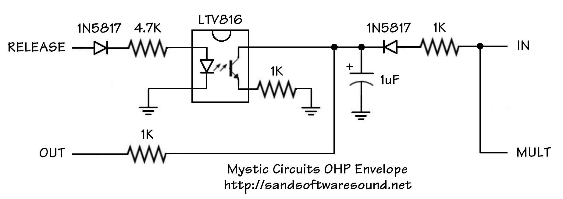
The 1uF capacitor is key to understanding the Envelope’s operation. The IN signal charges the 1uF capacitor while the phototransistor in the optoisolator (LTV816) discharges the capacitor to ground. The charge on the capacitor determines the OUT voltage. If you put audio into the Envelope, the capacitor smooths out the audio, leaving only the amplitude envelope.
The RELEASE signal controls the brightness of the LED in the optoisolator. The brightness controls the gate of the phototransistor. When the LED is brighter, the gate turns ON harder, more current flows, and the capacitor discharges faster.
Copyright © 2021 Paul J. Drongowski