
Beat Box is a lo-fi drum machine for Arduino. Here’s a quick rundown:
- 16 grungy, TR808-like rhythm instruments
- Up to eight instruments per pattern
- Up to five selectable patterns
- Adjustable tempo (60 BPM to 188 BPM)
- Full source code available including waveforms (samples)
- Write and compile your own patterns, drum kits and waveforms
- Built-in PWM signal generation into an external low pass filter
- 22,050Hz, 8-bit signed, mono waveforms for true lo-fi grunge
Here is an MP3 demo. I put the Beat Box output through a littleBits Filter module and Delay module. The demo sweeps the filter frequency from low to high and then increases the filter feedback to add tempo-synchronized echoes.
Beat Box does not use an external digital-to-analog converter (DAC). Instead, Beat Box uses the Arduino’s high resolution TIMER1 pulse width modulation (PWM) channel to drive an easy-to-build external low pass filter. Just four components! Of course, you’re welcome to send the audio into any downstream effects of your own like the littleBits filter module or delay module. This ultra-low cost approach adds to the lo-fi charm.
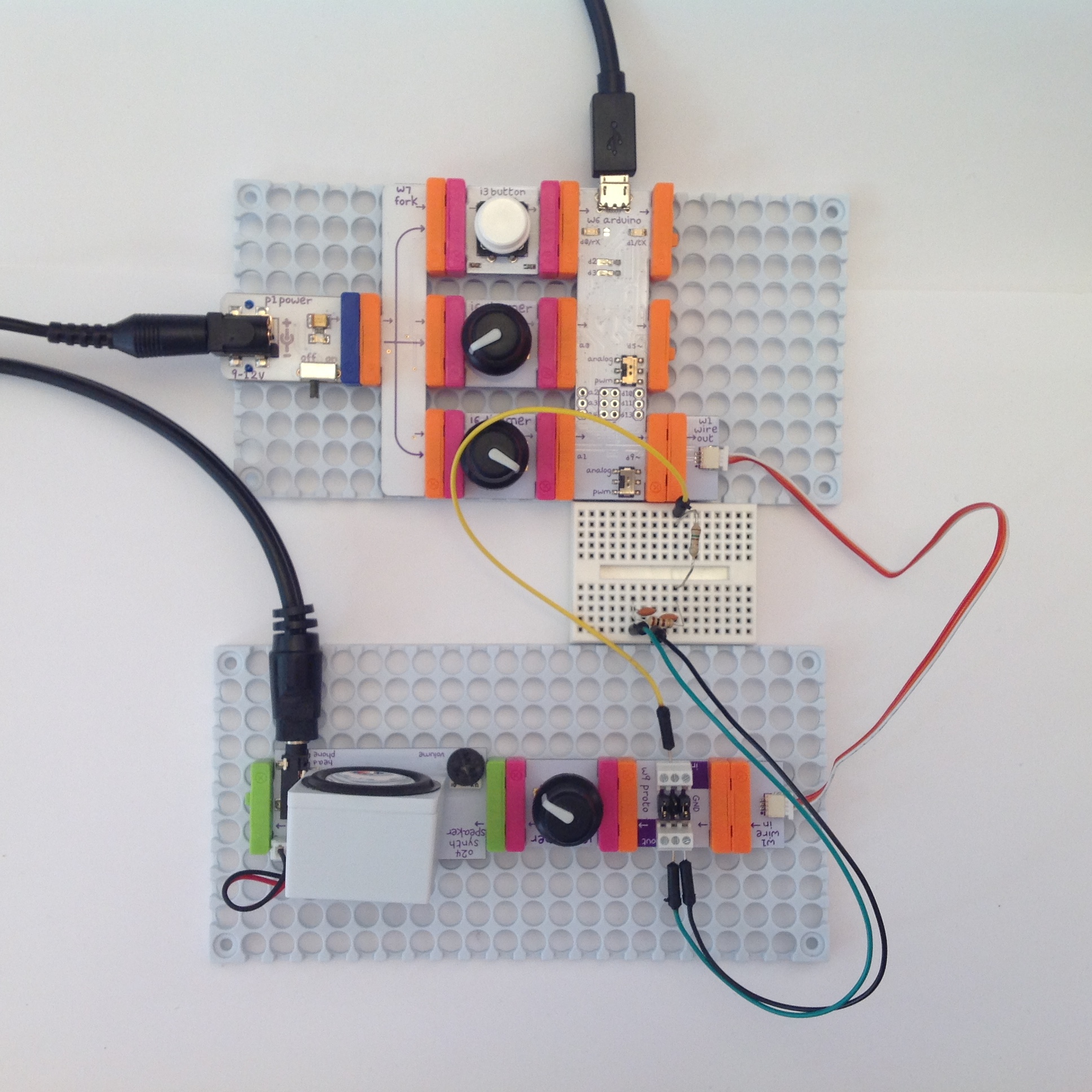
I constructed the Beat Box using the littleBits Arduino module. The littleBits Arduino module is software compatible with the Arduino Leonardo board. You shouldn’t have too much trouble porting the hardware design and code to Arduino UNO or some other Arduino processor board.
littleBits modules make assembly a breeze. (See the picture below.) No soldering is required. I built the low pass filter on a solderless breadboard. The filter breadboard connects to the main electronics through a littleBits Proto module. The Proto module has screw terminals for wire connections. (Did I say “No soldering?”)
Let’s dive into the hardware and software design.
Arduino and other main electronics
I built the main electronics on two littleBits mounting boards — one board for the Arduino and one board for filtering, volume control and audio output.
The Arduino mounting board consists of a power module, a fork module, a button module, two dimmer (potentiometer) modules and an Arduino module. The power module supplies electrical power to everything else by way of the fork module. There are three inputs to the Arduino:
- Tempo: A dimmer module connected to analog pin A0.
- Pattern select: A dimmer module connected to analog pin A1.
- A button module (not used by the sketch) connected to Arduino pin D0.
The Beat Box sketch does not use the button module, so if you have an idea, then hack away! The sketch reads A0 and A1 in order to set the tempo and to select a rhythm pattern. More about this later when I discuss the software design.
Set the PWM/analog switch for pin D9 to the PWM position. This passes the raw PWM signal to the output connector (“bitSnap” in littleBits terminology).
A littleBits Wire module connects the first board to the second board. It sends the PWM bit stream from Arduino pin D9 to the input of the low pass filter via a littleBits Proto module. The low pass filter ltself resides on a solderless breadboard. The Proto module is just a bridge between the breadboard and littleBits-land. The Proto module sends PWM bit stream to the low pass filter and receives the audio signal from the filter. The Proto module then sends the audio to a volume control implemented by a littleBits dimmer module. The volume control feeds the littleBits Synth Speaker which has a stereo 3.5mm output jack. I recommend playing the audio through external monitors because the Synth Speaker does not do justice to the low drum frequencies.
Low pass filter
The low pass filter is a passive, two-stage filter. The filter consists of only four components: two 150 ohm resistors and two 0.1uF disc capacitors. The filter corner frequency is about 10,610Hz. (See the schematic below.)
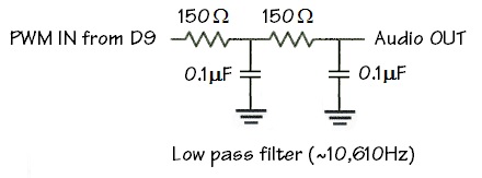
The filter smoothes out the PWM bit stream from Arduino pin D9. Pin D9, by the way, is the output from the high resolution timer, TIMER1, which actually generates the PWM signal.
The filter eliminates most of the conversion artifacts in the audio signal. You may still hear a high pitched whine at higher output levels, however. The high pitched whine is easily eliminated by the EQ or tone controls in downstream electronics, e.g., an amplifier, an external audio filter, etc. The littleBits filter module does the job and also let’s you play with its cutoff frequency and resonance in real-time.
I built the low pass filter on a solderless breadboard as shown in the pictures below. Simply follow the schematic and hook up the resistors and capacitors on your own breadboard.
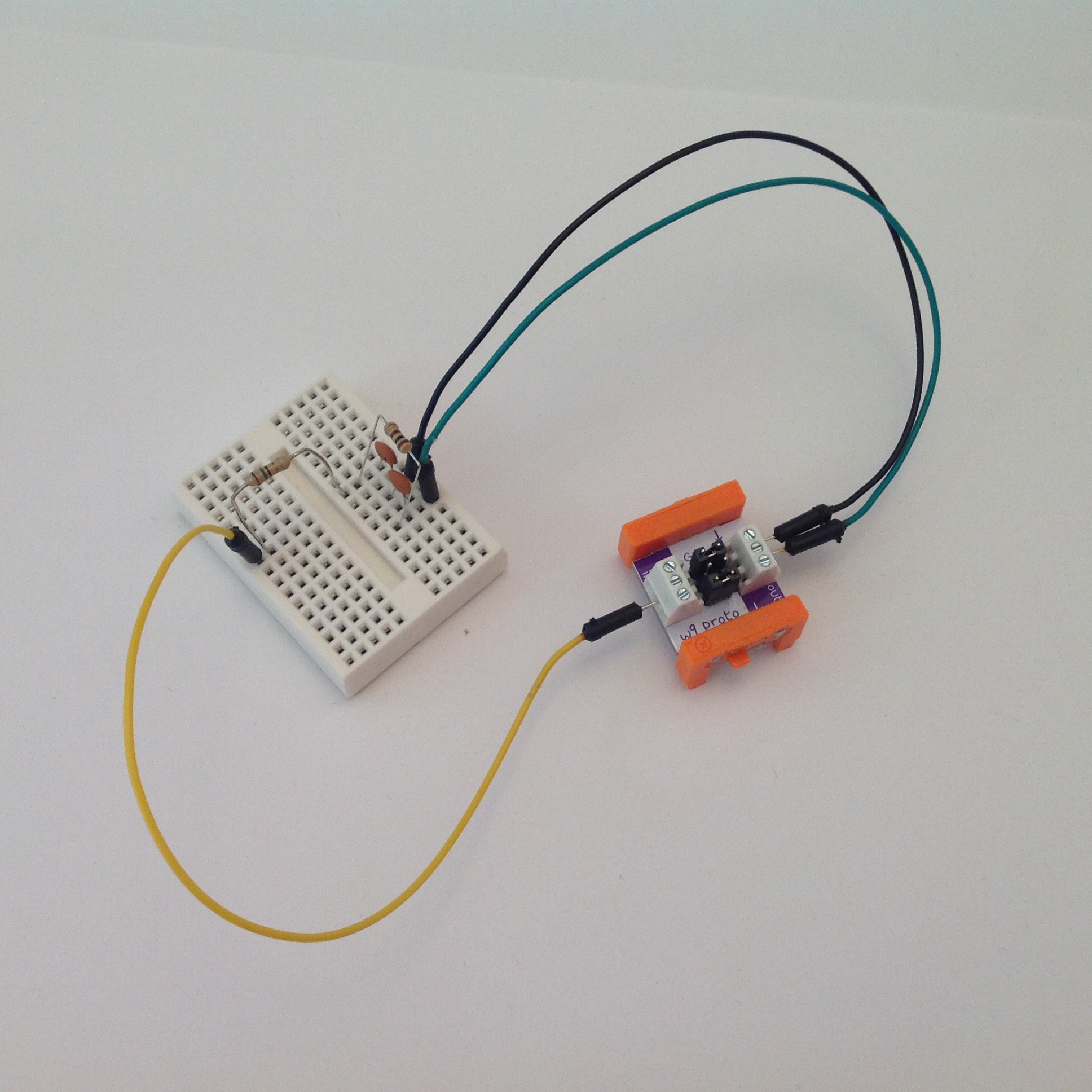
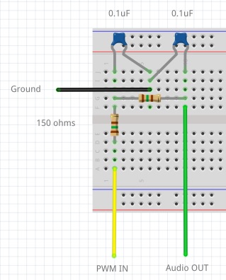
The breadboard connects to the main electronics through a littleBits Proto module. The yellow wire in the pictures carries the PWM bit stream to the input of the first filter stage. The green wire carries the filtered audio signal to the output of the Proto module. The black wire is ground.
I know this question is bound to come up. “Why didn’t you use the filter on the littleBits Arduino board?” The littleBits filter is too good at what it does! It’s designed for low bandwidth (low frequency) analog control — think “motors” — and the filter squeezes out just about all of the high frequency content from the audio. It makes a cymbal sound like a dull thud. Try it. You’ll see why I added a separate external low pass filter with a (much) higher corner frequency.
On to the software design!
TIMER1, interrupts and PWM
The Arduino Leonardo (and UNO) has three hardware timers:
- TIMER0 is a low resolution (8-bit) timer and implements the
delay()function. - TIMER1 has both a low resolution mode and a high resolution (16-bit) mode. It does not have an assigned function.
- TIMER2 is a low resolution timer and implements the
tone()function.
All three timers are capable of producing a PWM signal through a pin. Low resolution PWM, unfortunately, cannot adequately reproduce audio when converted. TIMER1’s high resolution mode, however, can reproduce audio after conversion although the result is somewhat lo-fi. In this application — rhythm for EDM — lo-fi is a sonic advantage!
TIMER1 is one complicated critter thanks to its different operating modes. If you are truly interested, I recommend reading about TIMER1 elsewhere. I’m only going to outline the bare essentials here. (Check out my earlier remarks about Arduino 16-bit PWM.)
TIMER1 has several counters and control registers (TCCR1A, TCCR1B, TIMSK1, ICR1H, ICR1L, OCR1AH, OCR1AL). For the sake of this project, TIMER1 has two relatively independent sides to its personality: bit capture and PWM generation. The Beat Box sketch configures the bit capture side to generate an interrupt at a 22,050Hz rate — the same sampling rate as the drum waveforms. The sketch configures the PWM side for 16-bit, phase correct, single PWM. It also turns on output pin 9 to unleash the PWM signal. (See the code fragment below.)
    //
    // TIMER1 PWM. Single PWM, phase correct, 22050KHz.
    // PWM_FREQ = 16,000,000 / 22,050 =  726 = 0x2D5
    // PWM_FREQ = 16,000,000 / 11,025 = 1451 = 0x5AB
    //
    #define PWM_FREQ   363

    void PwmSetup() {
      // Clear OC1 on compare match, 8-bit PWM
      //TCCR1A = _BV(COM1A1) | _BV(WGM10) ;
      TCCR1A = _BV(COM1A1) ;
      // PWM TOP is OCR1A,  No prescaler
      TCCR1B = _BV(WGM13) | _BV(CS10) ;
      // Generate interrupt on input capture
      TIMSK1 = _BV(ICIE1) ;
      // Set input capture register to sampling frequency
      ICR1H = (PWM_FREQ >> 8) ;
      ICR1L = (PWM_FREQ & 0xff) ;
      // Turn on the output pin D9
      DDRB |= _BV(5) ;
      sei() ;
    }
Once enabled, TIMER1 generates an interrupt at a 22,050Hz rate. The interrupt service routine (ISR) reads the next sample for each rhythm instrument, adds the samples together, and writes the sum to the PWM side of TIMER1. (See the following code fragment.)
//
// Interrupt service routine (ISR)
//
ISR(TIMER1_CAPT_vect) {
  register int16_t dacValue = 0 ;
  register int16_t sample = 0 ;
  if (sampleCounts[0] > 0) {
    sample = (int8_t)pgm_read_byte_near(
      sampleArrays[0]+sampleIndices[0]) ;
    dacValue += sample ;
    sampleIndices[0]++ ;
    sampleCounts[0]-- ;
  }
  .
  .
  .
  // Output through OC1A
  dacValue += 127 ;
  OCR1AH = (uint8_t) (dacValue >> 8) & 0xFF ;
  OCR1AL = (uint8_t) dacValue & 0xFF ;
}
I did not reproduce the entire ISR here because I manually unrolled a loop to scan the rhythm instruments, read the next sample for each and tally up an aggregate value (dacValue) for conversion via PWM.
TIMER1 is configured such that we get about 9 bits of digital audio resolution. This is not high fidelity (CD audio has 16 bits of resolution), but close enough for rock and roll (errrr, lo-fi EDM).
Waveforms, samples and PROGMEM
While we’re on the subject of samples, here’s the scoop on the instrument waveforms. Beat Box provides waveforms (“samples”) for sixteen rhythm instruments:
    Instrument   Abbreviation     Instrument   Abbreviation
    -----------  ------------     ----------   ------------
    Bass Drum         BD          Rimshot           RS
    Snare Drum        SD          Clave             CL
    Low Tom           LT          Handclap          CP
    Mid Tom           MT          Maracas           MA
    High Tom          HT          Cowbell           CB
    Low Conga         LC          Cymbal            CY
    Mid Conga         MC          Open High Hat     OH
    High Conga        HC          Closed High Hat   CH
Aficionados of the Roland TR-808 just lit up. Yes, this is lo-fi TR-808 — low sampling rate, bit crunched and severely trimmed short. Specifically, the waveforms are 22,050Hz, signed 8-bit, mono.
Once the Arduino runtime environment takes its share, only 2,560 bytes of RAM are available for the sketch and 28,672 bytes of program memory (PROGMEM). Clearly, RAM space is insufficient for instrument samples and there’s always the issue of loading samples into volatile dynamic memory. That leaves PROGMEM as the only option for sample storage. (One could add an SD card reader, but that’s a far more complicated hardware and software solution.)
Fortunately, sketches are typically small (even Beat Box) and the Arduino IDE compiler produces tight code. The Beat Box sketch needs a few thousand bytes of program memory leaving 20,000+ bytes available for samples. Even better, PROGMEM is non-volatile flash memory, so we don’t need to worry about waveforms disappearing after power-off.
To shorten a long story, waveforms are stored as arrays in PROGMEM. Unlike arrays in dynamic memory, the sketch reads the samples using the runtime function pgm_read_byte_near(). You can find more information about PROGMEM in the Arduino language reference.
In summary, the waveform representation favors small space: low sampling rate, low resolution, and mono. The real TR808 sounds have some nice long tails. Goodbye. They don’t fit in the Arduino’s tight memory and they’re gone. Bummer.
Kits, patterns and PROGMEM
Not all sixteen instruments are available at once. Instead, instruments are combined into eight instrument kits. There are four predefined kits: SH, CT, AD, and VR. A kit is usually associated with one or a few particular rhythm patterns. The kit provides the specific rhythm instruments needed by a pattern. Here is the code for the VR kit:
    //
    // VR kit
    //

    #define VR_BD 0b10000000
    #define VR_SD 0b01000000
    #define VR_LC 0b00100000
    #define VR_MC 0b00010000
    #define VR_HC 0b00001000
    #define VR_RS 0b00000100
    #define VR_OH 0b00000010
    #define VR_CH 0b00000001

    const int8_t* const vrWaveforms[8] PROGMEM  = {
      CHSamples, OHSamples, RSSamples, HCSamples,
      MCSamples, LCSamples, SDSamples, BDSamples
    } ;

    const int16_t PROGMEM vrWaveformSizes[8] = {
      CHSAMPLESSIZE, OHSAMPLESSIZE, RSSAMPLESSIZE, HCSAMPLESSIZE,
      MCSAMPLESSIZE, LCSAMPLESSIZE, SDSAMPLESSIZE, BDSAMPLESSIZE
    } ;
Each element of the vrWaveforms[] array points to the samples belonging to a rhythm instrument. Each element in the vrWaveformSizes[] array specifies the number of samples in the corresponding samples array.
Order is important! The #define macros specify the corresponence between an instrument’s samples and the pattern bit which triggers the instrument. In the example above, the lowest order bit (VR_CH) triggers the first instrument (CHSamples) and the highest order bit (VR_BD) triggers the last instrument (BDSamples).
By now, you probably know where I’m going with the representation of a rhythm pattern:
    #define VOODOOSIZE 16
    const uint8_t PROGMEM voodoo[VOODOOSIZE] = {
      0b10000001,
      0b00010001,
      0b00000001,
      0b00000100,
      0b11010001,
      0b00000001,
      0b00000010,
      0b00001101,
      0b10001001,
      0b00100001,
      0b00000001,
      0b00001010,
      0b11100001,
      0b00000001,
      0b00101101,
      0b00000001
    } ;
A rhythm pattern is an array of steps. Each step is a sixteenth note in duration. A step is a bit pattern. Each bit specifies a rhythm instrument to be triggered (or not) during the step. The positional relationship between bits in the pattern and instruments in the associated kit is important.
The sample playback scheme can sound eight instruments simultaneously. This performance limitation pretty much determines the kit and bit pattern size. Smaller pattern and kit arrays take less space in PROGMEM, too.
Sample playback
We’ve already discussed the interrupt service routine. The ISR is called at a 22,050Hz rate. It sums the next sample for each active rhythm instrument and writes the sum to TIMER1’s Output Compare Register (OCRA) that controls the pulse width. You can think of the ISR as an independent process that periodically wakes up and outputs a DAC value.
Code in the loop() function controls sample playback. Each iteration of loop() processes a step in the current rhythm pattern. It decodes the bits in the pattern step. When a bit is set for a rhythm instrument, it triggers playback of the instrument’s waveform by writing the number of samples to be played back into the element of sampleCounts[] which corresponds to the rhythm instrument. In other words, each element of sampleCounts[] acts as a flag; if the element is non-zero, then there are samples to be played and the instrument is triggered. The ISR decrements the sample count on each interrupt, so playback terminates with the last sample in the waveform.
In fact, there are several arrays which hold playback-related data:
    // Rhythm instrument control variables
    #define INSTRUMENTS 8
    const int8_t* sampleArrays[INSTRUMENTS] ;
    int16_t sampleSizes[INSTRUMENTS] ;
    int sampleCounts[INSTRUMENTS] ;
    int sampleIndices[INSTRUMENTS] ;
The arrays sampleArrays[] and sampleSizes[] are working storage in dynamic memory that hold information about the rhythm instruments in the current kit. This cuts down on calls to PROGMEM functions like pgm_read_byte_near(), presumably giving us a speed advantage. We want the interrupt service routine to run as fast as possible. That’s also why access to the arrays is “unrolled” in the ISR. Loop unrolling eliminates bookkeeping computations.
Pattern playback
Pattern playback is the next destination in our bottom-up tour of the Beat Box sketch.
Pattern playback is controlled by its own variables and pattern array in dynamic memory:
    // Pattern and pattern control variables
    int patternId = 0 ;
    int kitId = 0 ;
    int patternLength = 16 ;
    int patternIndex = 0 ;
    uint8_t pattern[64] ;
The currently selected pattern is stored in the array pattern[]. The loop() steps through the pattern array, keeping track of the current index in patternIndex. Playback loops back to the beginning of the pattern when the index hits the end of the pattern array(patternLength).
The loop() function calls delay() once per iteration. The delay time in milliseconds is equal to a sixteenth note playing at the chosen tempo in beats per minute (BPM). Thus, the pattern playback moves forward one sixteenth note per step.
Tempo and pattern selection
In addition to pattern playback, the loop() polls analog input pins A0 and A1 to detect changes to the tempo and pattern, respectively. The code remembers the old (previous) tempo and pattern input values. If a new input value is different, then the user has turned a dimmer wanting to make a change.
- When A0 changes, the sketch computes a new tempo and delay value. Tempo ranges from 60BPM to 188BPM.
- When A1 changes, the sketch calls
changePatternAndKit()to load a new kit and pattern into the working arrays in dynamic memory. The kit and pattern are loaded from PROGMEM.
The dimmer connected to pin A0 behaves like a five position selector switch. Each position selects a rhythm pattern.
There’s one final touch. The loop() flashes the transmit LED in time with the tempo (BPM). There are four Leonardo-specific macros to control the transmit (TX) and receive (RX) LEDs:
- TXLED1: Turn on the TX LED.
- TXLED0: Turn off the TX LED.
- RXLED1: Turn on the RX LED.
- RXLED0: Turn off the RX LED.
You will need to change this part of the sketch if you port the code from Leonardo to an Arduino UNO or MEGA.
Source code
There are four source code files:
- BeatBox.ino: The sketch including TIMER1 set-up and interrupt handler.
- waveforms.h: Samples for the sixteen rhythm instruments.
- kits.h: Rhythm kits needed by the example patterns.
- patterns.h: Exaample rhythm patterns.
All four files must reside in an Arduino IDE project directory named “BeatBox”.
The include file waveforms.h is long and boring, so I did not post it here as a WordPress page. Instead, you should download BeatBox.zip which contains all of the source, including waveforms.h. The ZIP file decompresses into a directory named “BeatBox”, leaving you ready to open the project in the Arduino IDE.
Copyright © 2016 Paul J. Drongowski