
I hope you had a chance to try the littleBits Arduino tone sequencer because it’s the starting point for my next project. The simple tone sequencer was featured as a project on the littleBits site.
The simple sequencer generates square waves through the Arduino’s digital pin D5 where the audio signal is sent to the synth speaker module. The sequencer sketch calls the Arduino tone() function to play notes. Notes are stored in a two dimensional array where the first column contains the pitches (expressed as a frequency in Hertz) and the second column contains the note durations (given in milliseconds). The pitches and durations are defined as symbolic constants, making it more convenient to code simple songs and loops.
The square waves produced on pin D5 are nasty sounding things! The harmonics are biting and the only dynamic level is LOUD. It’s tiresome to listen to musical sounds without dynamic timbre and volume. Time for a little postprocessing with the littleBits envelope and filter modules.
This project keeps the Arduino portion of the simple tone sequencer intact as shown in the image below. (Please click images to get higher resolution.)
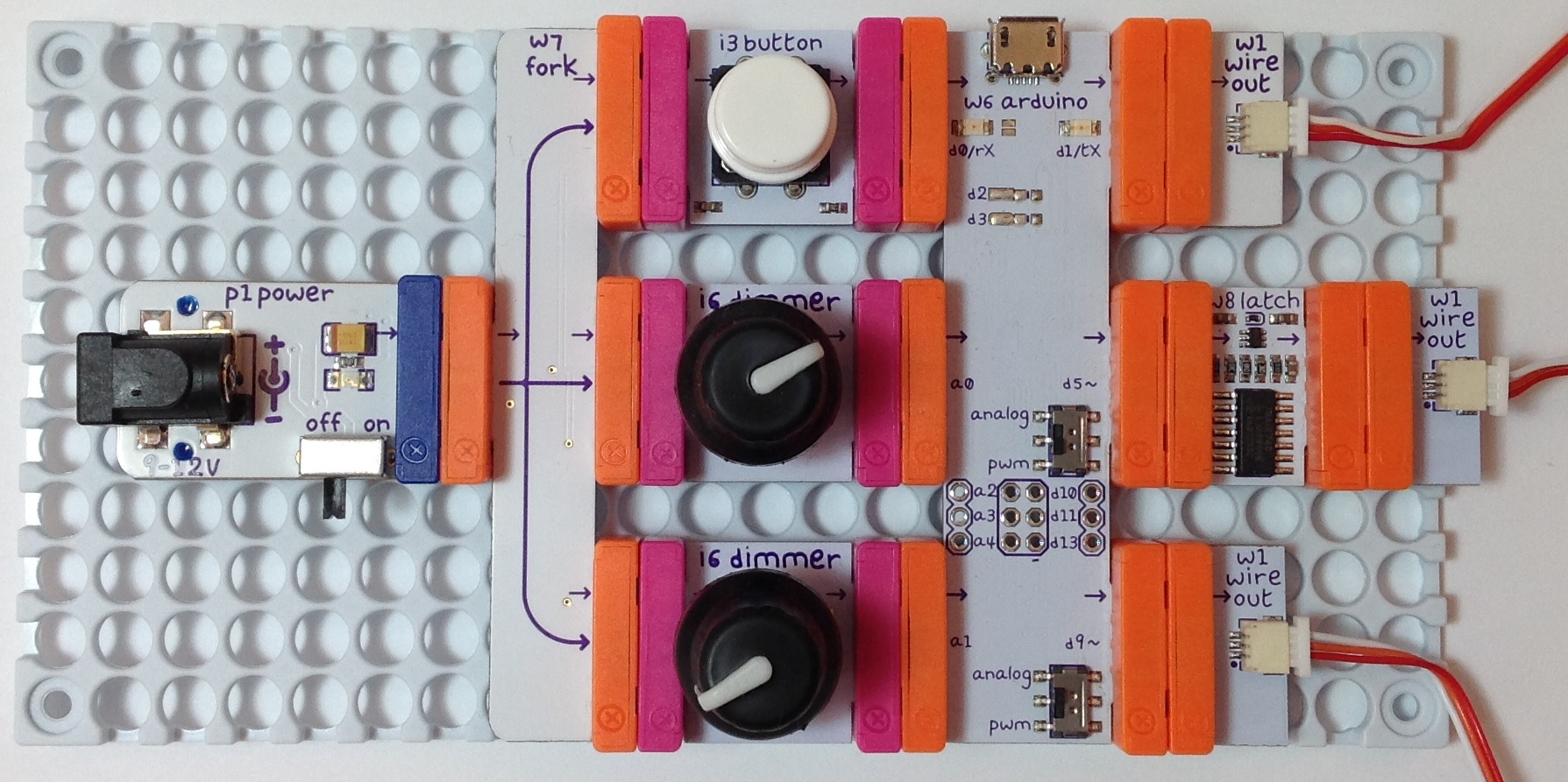
The new design still generates square waves through pin D5. However, you’ll notice that I added a latch module to pin D5. The latch module drops the note one octave (i.e., it divides the frequency of the square wave by two). When I first built this project, I didn’t use the latch module. Without the latch, the sound kept glitching on the lowest notes. After much experimentation and debugging, I determined that the Arduino tone() function sometimes has trouble playing notes below B2 (about 123 Hz). Since I like to program bass sequences, I really wanted to play low notes. So, I raised the notes in the sequence by one octave and then dropped the notes back down with the latch.
This project puts the two dimmers in the Arduino subsystem to work. The dimmers are connected to Arduino analog pins A0 and A1. The dimmer connected to A0 controls the attack and release rate of the filter modulation signal. The dimmer connected to pin A1 sets the modulation sustain level. More about this later.
You probably noticed that all three outputs from the Arduino subsystem are sent out through wires. These wires connect to the synth subsystem on a separate mounting board. The three Arduino subsystem outputs are:
- Trigger/gate: Pin D1
- Square waves: Via the latch connected to pin D5
- Filter modulation: Pin D9
The PWM/analog switch for pin D5 is set to the PWM position. We want those high amplitude square waves for the audio signal. The PWM/analog switch for pin D9 is set to the analog position because we want to produce an analog voltage to modulate the filter module. Pin D1 is always digital — just what we want for an envelope trigger (gate) signal.
The picture below shows the synthesizer portion of the hardware design. The signal processing chain consists of a filter module feeding an envelope module. The audio is sent from the output of the envelope module through a volume control dimmer to the synth speaker module.
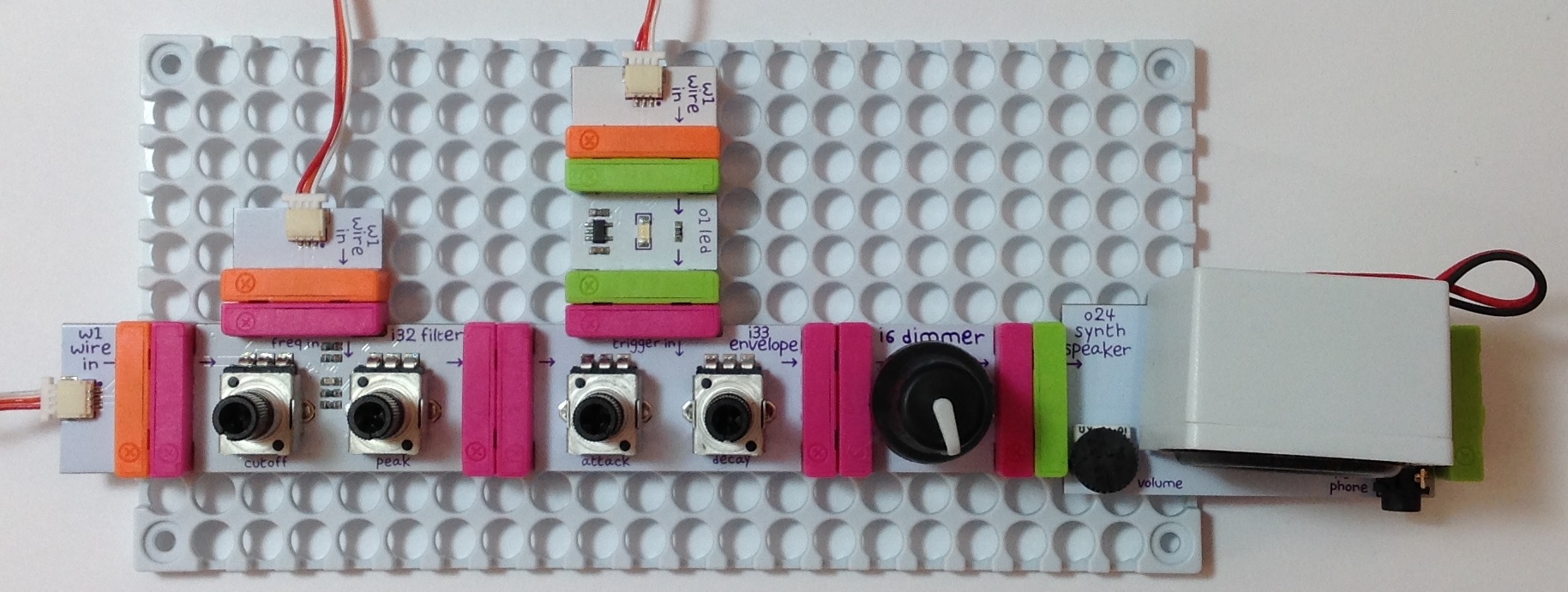
In terms of subsystem to subsystem wiring, the square waves are sent to the audio input of the filter module. The filter modulation signal is sent from Arduino pin D9 to the filter modulation input. The trigger is sent from pin D1 to the envelope’s trigger input via an LED module. The LED module is quite handy for debugging and tweaking the attack and decay settings. The LED shows us when the trigger signal is HIGH and LOW. I haven’t tried it yet, but you might want to put a bargraph module on the filter modulation input to see how the modulation signal changes.
The hardware design is pretty straightforward. The real fun (and challenge) is to modify the original sequencer sketch:
- To generate the envelope trigger signal, and
- To generate the filter modulation signal.
Let’s take a look at changes in the code.
Source code files
The source code is organized into three files:
- ToneFreq.h: Symbolic constants for note pitches (e.g., NOTE_C4)
- ToneNote.h: Symbolic constants for note durations (e.g., QUARTER)
- GateModSeq.ino: Main sketch file
ToneFreq.h and ToneNote.h were used in the simple tone sequencer project. I reused them here without making any changes. The main source file, GateModSeq.ino, does the heavy lifting and has several changes (with respect to ToneTest.ino). All three files must be stored in the same directory named “GateModSeq”.
Professional programmers reuse design and code as much as possible. This style of coding is sometimes called “copy and modify.” I copied the code for the simple tone sequencer and then modified it for the new application. Reusing code reduces development time and let’s you build on code that has already been tried, tested and debugged.
Definitions and declarations
First, I declare two variables to refer to the analog input pins A0 and A1:
    int arInputPin = 0 ;
    int levelInputPin = 1 ;
Then I declare three variables to refer to the output pins D1, D5, and D9:
    int gatePin = 1 ;
    int tonePin = 5 ;
    int modPin = 9 ;
It’s standard Arduino coding practice to declare the pins upfront in this way.
Three variables control the selection and playback of notes in the sequence[][] array:
    int noteIndex = 0 ;
    int note = 0 ;
    int duration = 0 ;
These variables work in the same fashion as the simple tone sequencer. Please see that project’s design for more information.
Five variables control filter modulation:
    int attackDuration = 0 ;
    int releaseDuration = 0 ;
    int sustainDuration = 0 ;
    int sustainLevel = 64 ;
    int arIncrement = 0 ;
    int modValue = 0 ;
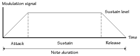
I divide the note playback time (duration) into three periods:
- Attack: The time to ramp up the modulation signal
- Sustain: The time to hold the modulation signal at the sustain level
- Release: The time to ramp down the modulation signal to zero
The following picture shows the intended shape of the modulation signal. The variable modValue stores the current modulation signal value.
Finally, there are the definitions and declarations for the musical notes, including the two dimensional array sequence[][] which contains the note pitches and durations:
#define TEMPO    (90)
#define REST     -1
#define SEQUENCE 18
#define START    15
int sequence[SEQUENCE][2] = {
  NOTE_As3, EIGHTH,
  REST,     SIXTEENTH,
  NOTE_Gs4, SIXTEENTH,
  REST,     EIGHTH,
  NOTE_As4, EIGHTH,
  REST,     EIGHTH,
  NOTE_C4,  EIGHTH,
  NOTE_Cs4, EIGHTH,
  NOTE_D4,  EIGHTH,
  NOTE_Ds4, EIGHTH,
  REST,     SIXTEENTH,
  NOTE_As4, SIXTEENTH,
  REST,     EIGHTH,
  NOTE_Cs5, EIGHTH,
  REST,     EIGHTH,
  NOTE_G3,  EIGHTH,
  NOTE_Gs3, EIGHTH,
  NOTE_A3,  EIGHTH
} ;
The note names and durations are defined in the include files.
Generating the trigger signal
No suspense or drama necessary. We set the trigger signal HIGH when the sequencer begins to play a note and we set the trigger signal LOW when the note stops playing.
Here is the code for the setup() function:
    void setup() {
      Serial.begin(9600) ;
      // Define pin modes
      pinMode(gatePin, OUTPUT) ;
      // Initialize pin values
      digitalWrite(gatePin, LOW) ;
      // Start playing the first note in the sequence
      // This note could be a pick-up!
      noteIndex = START ;
      note = sequence[noteIndex][0] ;
      duration = sequence[noteIndex][1] ;
      computeModValues() ;
      if (note != REST) {
        tone(tonePin, note) ;
        digitalWrite(gatePin, HIGH) ;
      }
    }
Let’s focus for a second on the lines that deal with the trigger signal. The function initializes the gate (trigger) pin mode and sets its value to LOW:
    // Define pin modes
    pinMode(gatePin, OUTPUT) ;
    // Initialize pin values
    digitalWrite(gatePin, LOW) ;
When the function starts playing the first note, it sets the gate pin HIGH:
    if (note != REST) {
      tone(tonePin, note) ;
      digitalWrite(gatePin, HIGH) ;
    }
If you’re not familiar with the Arduino pinMode() and digitalWrite() functions, then check out these pages: pinMode() and digitalWrite().
Here is the code for the loop() function:
    void loop() {
      delay(1) ;
      duration-- ;
      if (duration <= 0) {
        // Current note has expired.
        noTone(tonePin) ;
        digitalWrite(gatePin, LOW) ;
        delay(1) ;
        // Find the next note to be played
        if (noteIndex >= (SEQUENCE-1)) {
            noteIndex = 0 ;
        } else {
            noteIndex += 1 ;
        }
        note = sequence[noteIndex][0] ;
        duration = sequence[noteIndex][1] ;
        computeModValues() ;
        // Start playing the next note
        if (note != REST) {
          tone(tonePin, note) ;
          digitalWrite(gatePin, HIGH) ;
        }
      } else {
        // Note continues. Adjust modulation value.
        analogWrite(modPin, modValue) ;
        if (attackDuration > 0) {
          attackDuration-- ;
          modValue += arIncrement ;
        } else if (sustainDuration > 0) {
          sustainDuration-- ;
          modValue = sustainLevel ;
        } else if (releaseDuration > 0) {
          releaseDuration-- ;
          modValue -= arIncrement ;
        }
      }
    }
The note sequencing aspect of the design remains the same from the simple tone sequence sketch.
Again, let’s focus on the lines for the trigger signal. The code sets the gate pin LOW when the current note has expired:
    // Current note has expired.
    noTone(tonePin) ;
    digitalWrite(gatePin, LOW) ;
    delay(1) ;
I inserted an extra one millisecond delay in order to give the envelope module time to settle. One millisecond is perhaps a little too long and throws off the BPM timing. However, it’s the shortest amount of time that we can delay execution.
The code sets the gate pin to HIGH when starting a new note:
    if (note != REST) {
      tone(tonePin, note) ;
      digitalWrite(gatePin, HIGH) ;
    }
Pretty simple, eh?
Generating the modulation signal
The dimmers connected to pins A0 and A1 determine the behavior of the modulation signal. The function computeModValues() reads A0 and A1, and computes the attack duration, sustain duration, release duration and attack/release change increment. Here is the code for the function:
    void computeModValues() {
      int arValue ;
      sustainLevel = analogRead(levelInputPin) >> 2 ;
      arValue = analogRead(arInputPin) >> 4 ;
      attackDuration = arValue ;
      sustainDuration = duration - (arValue << 1) ;
      releaseDuration = arValue ;
      arIncrement = sustainLevel / arValue ;
      modValue = 0 ;
    }
The function computeModValues() samples the attack/release time pin (A0) and the sustain level pin (A1):
    sustainLevel = analogRead(levelInputPin) >> 2 ;
    arValue = analogRead(arInputPin) >> 4 ;
The function analogRead() returns a value in the range from 0 to 1023. (Read about analogRead().) The shift operations scale the input values into useful ranges:
- Sustain level from 0 to 255
- Attack/release time from 0 to 63
Shift operations are much faster than integer division. Hey, don't be afraid to try different values or computations here!
The attack and release durations are set to the arValue:
    attackDuration = arValue ;
    sustainDuration = duration - (arValue << 1) ;
    releaseDuration = arValue ;
    arIncrement = sustainLevel / arValue ;
    modValue = 0 ;
The attack and release ramp up and down, respectively, at the same rate. The attack/release increment is the slope of the ramp leading up to the sustain level. The integer division truncates the result. I probably should have included code to quasi-round the result. The initial modulation value (modValue) is zero.
Why didn't I use floating point? The Arduino processor does not have floating point instructions. Floating point arithmetic must be performed in software. Therefore, floating point computations are very slow.
The functions setup() and loop() call computeModValues() before starting a new note. This sets up all of the filter modulation variables before playback. The function loop() has a new block of code to handle filter modulation:
    if (duration <= 0) {
      ...
    } else {
      // Note continues. Adjust modulation value.
      analogWrite(modPin, modValue) ;
      if (attackDuration > 0) {
        attackDuration-- ;
        modValue += arIncrement ;
      } else if (sustainDuration > 0) {
        sustainDuration-- ;
        modValue = sustainLevel ;
      } else if (releaseDuration > 0) {
        releaseDuration-- ;
        modValue -= arIncrement ;
      }
    }
The code in the else clause executes when a note is still active and is playing. It writes out the current modulation value by calling analogWrite(). (Read about analogWrite().) Then, it computes the next modulation value depending on the period (attack, sustain, release). If the attack period has not expired, then the code decrements the attack duration and increases the modulation value by arIncrement:
      attackDuration-- ;
      modValue += arIncrement ;
If the attack period has expired, the code moves on to the sustain period, and so forth.
Debugging tips
You probably noticed that the setup() function initializes the Arduino Serial port:
Serial.begin(9600) ;
Use Serial.print() and Serial.println() to send trace and debug messages to the Arduino IDE Serial Monitor window. It's a good way to trace execution and values when testing the sketch. I usually remove test code (including messages to the Serial port) once the sketch is up and running correctly.
I hope you enjoyed this project. It demonstrates how an Arduino can extend the capabilities of the littleBits Synth Kit. Hack away and have fun!
Just in case you missed the links to the source code files, here they are again:
- ToneFreq.h: Symbolic constants for note pitches (e.g., NOTE_C4)
- ToneNote.h: Symbolic constants for note durations (e.g., QUARTER)
- GateModSeq.ino: Main sketch file
The two include files are also used in the simple tone sequencer project for littleBits Arduino.
Copyright © 2016 Paul J. Drongowski