Polyphonic Arduino synthesizer

If you’re interested in building an Arduino-based ROM-pler, this next project is for you!

One of my long term dreams is to build a low-cost 60s-style combo organ. My latest project uses an Arduino UNO as a sample playback, sound synthesis engine. Although the waveforms are taken from the old VOX Continental and Farfisa Mini Compact organs, the design and code could easily use single cycle waveforms from a vintage synth, a string machine, your first born child, whatever! The 60s combo organ project is essentially a software ROM-pler that plays back up to five waveforms at a 22,050Hz sampling rate.

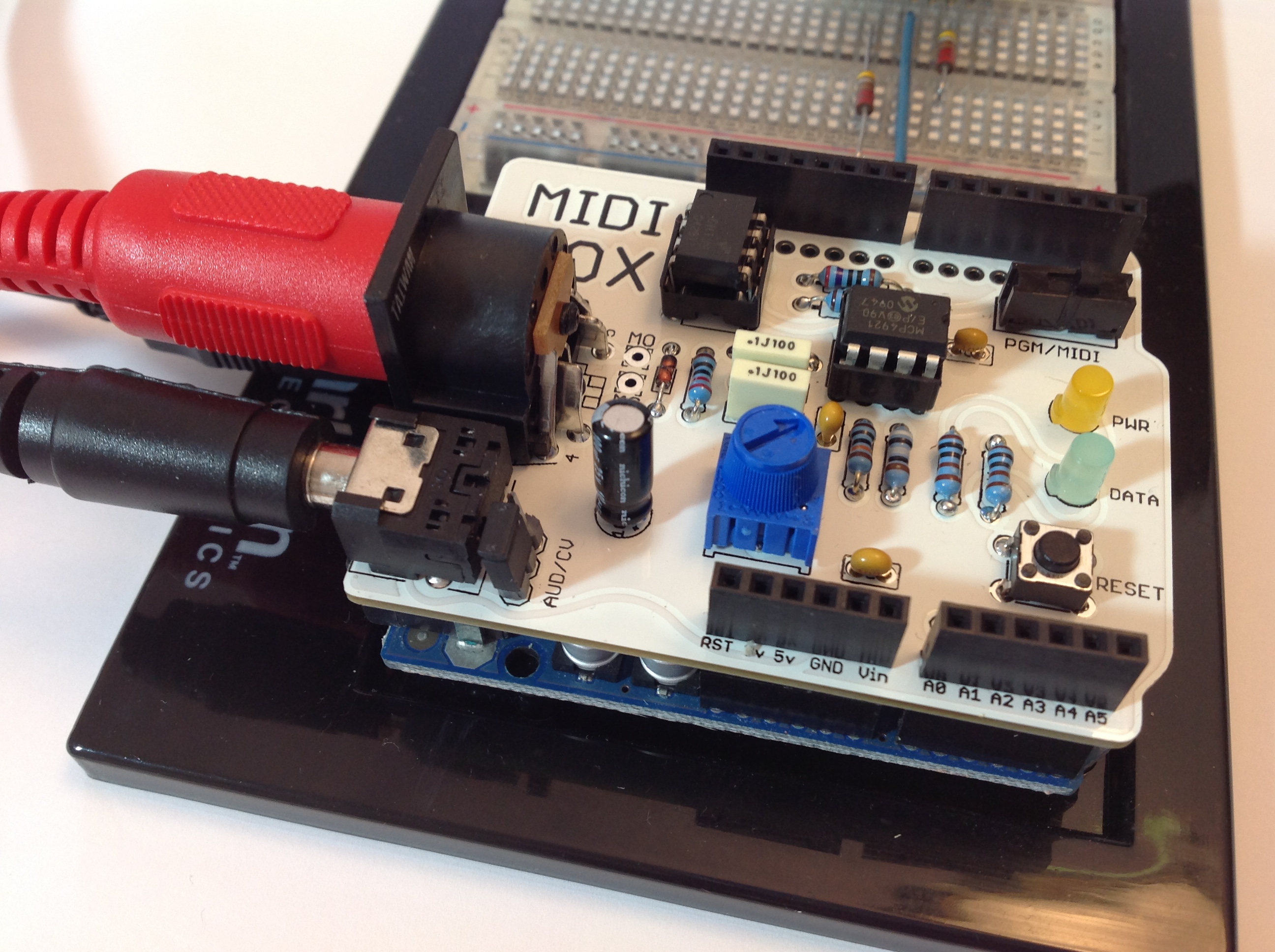
The project hardware consists of an Arduino UNO and a Narbotic Instruments MidiVOX shield. The MidiVOX shield has a Microchip Technologies MCP4921 12-bit digital to analog converter (DAC) and an opto-isolated MIDI input. Although the MidiVOX is no longer in production, it’s basic circuitry is easy to recreate; several other popular audio shields use the MCP4921.

Waveforms are stored in the Arduino’s program memory (PROGMEM), just like code. Program memory is non-volatile and the waveforms are ready to go just like a pre-loaded sketch. The combo organ sketch sets up TIMER1 to generate interrupts at a 22,050Hz sample playback rate. The interrupt handler reads the next sample for each of five virtual tone generators, sums the samples together, and writes the next aggregate sample to the DAC.

MIDI communication is performed through the standard Arduino MIDI library (version 4.2). The sketch registers two callback functions via the library: a note ON handler and a note OFF handler. The MIDI note handlers configure the five virtual tone generators. The sketch’s loop() function is trivial — it merely calls the MIDI library read() function and checks a reset button on the MidiVOX shield.

We all know that Direct Digital Synthesis (DDS) — the usual approach for sample playback — is a compute intensive technique for sound synthesis. DDS dynamically shifts the pitch of a stored waveform from its root pitch (the frequency of the sampled note) to the target pitch (the frequency of the MIDI note played by the musician). DDS performs waveform pitch-shifting through phase accumulation and interpolation. Floating point arithmetic is too slow and most DDS implementations use fixed point arithmetic. Even then, the computational load is heavy.

So, how did I achieve five note polyphony? Instead of storing a single waveform at a single root pitch, my approach stores twelve waveforms — one waveform for each basic pitch in the chromatic scale. The algorithm uses integer phase increments, thereby eliminating floating or fixed point arithmetic and interpolation entirely. The approach requires more space, but is quite fast. Each sampled instrument occupies 20% of program memory, allowing up to four different instruments before running out of PROGMEM.

Here are two quick MP3 demo files: a Farfisa-type sound and a and a VOX-type sound. I created the vibrato by routing the audio signal through an inexpensive Behringer UV300 vibrato pedal.

As usual, we always publish code. Need a cheap ROM-pler? Now you’ve got one!

Update 22 July 2016: If you’re into retro, be sure to check out the Arduino lo-fi beat box project. Filled with lo-fi TR-808 goodness!

MidiVOX: An appreciation and review

They just don’t make ’em like they used to. In the case, of the Narbotic Instruments MidiVOX shield for Arduino, I really mean it!

The MidiVox is a bit of a blast from the past as Narbotic no longer manufacture and sell the MidiVOX shield kit. Major bummer. Luckily, I purchased one of these little gems from the MakerShed when the shields were available a few years ago. Narbotic kindly maintain the design information and code on their Web site.

To me, the MidiVox is a most logical combination of a MIDI IN port and a 12-bit digital-to-analog converter (DAC). The MIDI port incorporates a 6N138 optocoupler for electrical isolation and a 5-pin DIN connector. The port is connected through a “PGM/MIDI” switch to Arduino digital pin D0, also known as the serial receive (RX) pin. The PGM position connects the serial pin the usual way in order to download to the Arduino. The MIDI position connects the Arduino serial RX pin to the MIDI IN circuitry. The switch component is robust and is easily accessible when the MidiVOX is on top of the Arduino and/or other shields.

The 12-bit DAC is a Microchip Technology MCP4921. This DAC is used in several other audio shield designs including the Adafruit Wave Shield and the Nootropic Design Audio Hacker Kit. The MCP4921 connects to the Arduino SPI port through digital pins D13 (SCK), D11 (MOSI), and D9 (chip select/slave select). Conventional practice recommends using D10 as slave select (SS), but it isn’t a big deal to use D9 instead as this is mainly a software issue. Slave Select (called “chip select” in the MCP4921) chooses and enables communication with the slave device. This capability is essential when more than one device is connected to the same SPI interface as in the case of the Nootropic Audio Hacker shield.

Although it seems like a no-brainer to connect all SPI devices to the Arduino SPI pins, the Adafruit Wave Shield does not follow this approach. It connects the SD card interface to the SPI pins, but connects its MCP4921 to three ordinary digital pins. The Wave shield software bit-bangs the digital pins to transfer data to its DAC. I’m not a fan of this approach, preferring to use standard libraries instead of possibly buggy, poorly documented bit twiddling code.

The MidiVOX shield implements a 2-stage, passive filter following the DAC output. The MidiVOX sends a mono signal through an on-board trim pot into a 3.5mm audio output jack. Trim pots are usually rated for a relatively small number of operating cycles, so it’s best to set this level once and make volume adjusts at an external mixer, preamp, or whatever.

The MidiVOX shield provides a DATA LED controlled by digital pin D7. The shield also has a RESET button (momentary contact switch) connected to digital pin D6. This button is ACTIVE LOW, meaning that the button pulls D6 to ground when it is pressed. Therefore, the pin mode should be configured as INPUT_PULLUP such that D6 is pulled up internally when the button is not pressed (i.e., the momentary contact switch is open).

Construction was easy. The resistors have five color bands, but don’t let this throw you off. The construction directions give the correct color code and you can (and should!) always check resistor values with a meter before insertion and soldering. I replaced the basic header pins with “stackable headers” (two 8-pin and two 6-pin). Stackable headers provide a way to make easy external connections to the shield stack from a breadboard, etc.

The completed board is shown in the photo below. The MidiVOX is stacked on an Arduino UNO with the USB, audio and MIDI cables, and is ready to go.

MidiVox

I wrote a diagnostic sketch to check out the different parts of the MidiVOX. I wish manufacturers would provide check-out sketches instead of relying on somebody’s possibly flaky application sketch for smoke testing. If something is busted, it’s important to find it early through a directed test that isolates the failure. Fortunately, everything checked out OK the first time!

The MidiVOX diagnostic program is an Arduino sketch to check out parts of a Narbotic Instruments MidiVOX shield. Rename the “loop” functions and rebuild in order to test a particular section of the shield.

Since the MidiVOX is discontinued, we’re all out of luck if we want to get (another) one. However, I strongly recommend studying the MidiVOX design. When I first got started with Arduino and MIDI, I borrowed the MIDI IN circuitry and the low pass filter design. These are simple, solid circuits and are good basic building blocks for other designs and applications.

Where to next? My dream is to build a low-cost 60s combo organ with the era-appropriate look and sound. The organ would look like a Vox Continental with a Z-shaped chrome stand and bright red Tolex covering. It would sound like either a Farfisa or a Vox — nothing too nuanced with all of the drawbars or tabs turned on. I’d like to use a cheap and lightweight MIDI controller as the keyboard. The controller would drive a low-cost (Arduino-based?) sound generator. I’m hacking out a prototype using an Arduino UNO and the MidiVOX shield. More to come…

Prototino in progress

This week I got rolling on my next MIDI project — a mini MIDI controller with two knobs (potentiometers) and two buttons. I intend to mount the electronics in a Hammond 1991XXBBK enclosure, also known as an (ABS) stompbox. Plastic is OK because the box will reside by the pitch and modulation wheels on the Yamaha PSR-S950 arranger workstation. The plastic is less likely to mar the finish of the keyboard. (I hate scratches.) The ultimate goal is to augment the real-time control provided by the wheels.

The area next to the wheels is fairly small and a stompbox fits into it neatly. A stompbox is a fairly small, shallow box, so I needed an Arduino-based prototyping board that fits into a small enclosure. I first consider an Arduino plus prototyping shield combo, but rejected that solution. The Arduino + shield stack fit into a standard Arduino enclosure about the same size as the 1991, however, the pad-per-hole layout would have made soldering a bear.

Enter the Spikenzielabs Prototino. The Prototino is roughly 2 1/8 inches by 2 7/8 inches in size, compatible with the 1991. Its prototyping area uses the more standard DIP layout with two and three hole pads. This layout is soldering friendly. About one third of the surface area is taken by a minimal Arduino implementation: an ATMega 328P, crystal, power regulation and ICSP/FTDI connections. The voltage regulator is optional and I elected to leave it off in favor of an external 5V center positive power adapter. Here’s a picture of the assembled Prototino before pots and switches.

Prototino

The connector at the end of the long tail is a 2.1mm power connector. This will eventually be mounted through a hole in the side of the 1991 enclosure along with a 3.5mm stereo jack for the MIDI OUT port.

The Spikenzielabs’ directions are decent enough, but here’s a few more tips. The directions identify the optional power components to be omitted during assembly. The directions do not mention where to make the +5VDC and ground connections, however. As you can see in the picture, power and ground are connected to the +5V and GND pads in the prototyping area.

The directions also describe how to connect the FTDI cable. I have a Sparkfun 5V FTDI cable and decided to go that route for programming. The directions are a little sketchy (no pun intended) on how to configure the IDE for the Prototino. This led to the usual scrambling around in the Device Manager, etc. when the IDE wouldn’t communicate with the Prototino. Yes, you do need to select the correct COM port. You also need to select the appropriate board. With the Sparkfun cable, choose “Arduino Pro or Pro Mini” from the list of boards. This always seems to be a hassle and probably puts off a lot of beginning makers.

Finally, now that the power light comes on and the sketch is downloaded, how do we really know that the Prototino is operating normally? A stock Arduino UNO, for example, has an LED tied to one of the pins and comes preloaded with the blink sketch to turn the LED ON and OFF. The Prototino just sits there. Fortunately, one can easily whip up a sketch that uses the serial port and serial port monitor to see if the Prototino is genuinely alive. The setup() function needs to turn on the serial port and display a message:

    Serial.begin(9600) ;
    Serial.println("Hello world.\n") ;

The loop function can do something playful, if you wish. Compile and download the sketch, then look for the output in the IDE’s serial port monitor.

Experience with the Prototino has been positive so far. I plan to mount pots and switches on the back side of the Prototino and to mount the Prototino to the lid of 1991 enclosure. This will let me connect the FTDI cable to the Prototino and program the device in situ. Stay tuned!

DangerShield Drawbars

Just a quick post to mention the new Arduino section of the web site.

The first page in the new section describes the DangerShield Drawbars project that I started last March! This project uses the Sparkfun DangerShield (3 sliders, 3 buttons, 2 LEDs and a seven segment display) and an Arduino UNO to implement a basic MIDI drawbar controller for the Yamaha PSR-S950 arranger workstation. “Why not use one of the many available MIDI controllers?”, you ask. Well, the PSR (and Tyros) drawbars respond to a proprietary Yamaha System Exclusive (SysEx) MIDI message, not the usual MIDI continuous controller (CC) messages. The MIDI controllers on the market use MIDI CC, not SysEx. Thus, it made sense to whip up an Arduino-based controller in order to synthesize and send the appropriate control message.

The DangerShield Drawbars can and do control the PSR’s virtual drawbars. That’s the good news. The bad news is that I designed a rather complicated user interface (UI) in order to control nine virtual drawbars and the simulated Hammond percussion and vibrato with just three slide potentiometers. This was a serious overreach producing a less than intuitive, modal UI. If I attack this problem again, I will build a controller with one physical control per parameter, i.e., nine physical sliders for the drawbars and a handful of switches for percussion and vibrato. This approach should produce a more playable controller.

In the meantime, I’ve started to plan a new MIDI controller project and just discovered the SpikenzieLabs Prototino ATMega328 Kit. This board puts an Arduino-compatible ATMega328 on a protoboard with a very nice usable layout. The well-known Arduino proto shield (A000077), which I considered first, uses a pad-per-hole layout for prototyping. It’s not easy to solder circuits together with pad-per-hole. The Prototino layout is a more conventional breadboard-like design with plenty of 2- and 3-hole pads for making connections. I can’t wait to try it out!

Sparkfun Danger Shield

Sparkfun is one of my favorite companies. I like their products and their service is very good and reliable. I’ve learned a lot by studying their designs and I especially like their commitment to education.

Previously, I built two Sparkfun kits: the Redboard PTH Arduino and the MIDI break-out board. I have several more kits on hand to satisfy the occasional urge to solder!

Recently, I built a Sparkfun Danger Shield, hoping to use it as part of a MIDI drawbar controller. The code for the controller is still a work in progress. So, in the meantime, here is a micro-review of the Danger Shield.

The Danger Shield is a “jack of all trades” for input to an Arduino. It has three large sliders, three momentary contact buttons, one temperature sensor, one light sensor, and a capacitive touch sensor. The Danger Shield also provides basic output/display capability, too. The shield has two yellow LEDs, a seven-segment display, and a buzzer. For the MIDI controller project, I’m mainly interested in the sliders, buttons, LEDs and seven-segment display. However, I can see some creative possibilities for the other sensors in MIDI control.

Kit assembly went quite well, taking about two hours total. I think that a beginner could put one together without too much trouble. There was only one minor hang-up. The on-line assembly instructions are out-of-date. Two decoupling capacitors were added to the design after the instructions were published. One capacitor is mounted near the temperature sensor and the other capacitor is mounted near the shift register integrated circuit. This could trip up a beginner since they will have two small parts left over if they simply follow directions!

DangerShield

Sparkfun thoughtfully provide an Arduino Sketch (program) to test the sliders, buttons, etc. This is a great idea and I wish that more companies provided test programs with their products. When you build a kit, you really want to know if everything works before you design the kit into an experiment or prototype. Unfortunately, the test program expects the cap sense code to be installed as an IDE library. This dependency could trip up a beginner since they would need to learn how to install library code before running the test program. Since I didn’t intend to use the cap sense pad right away, I commented out the cap sense code and tested everything else.

The one thing that surprised me is the physical size of the shield. It is much bigger than the standard Arduino footprint. I had originally intended to stack the Danger Shield, the MIDI break-out board and the Arduino on a Liquidware side-by-side extender. This approach would have saved me the effort of whipping up a 5-pin MIDI OUT port. Unfortunately, the large size of the Danger Shield prevents much stacking.

I decided to prototype on an Arduino UNO which is installed on a plastic Arduino and breadboard holder. The Danger Shield is stacked on top of the Arduino UNO. The 5-pin MIDI OUT port resides on the breadboard. I built a 5-pin DIN break-out board to securely attach the 5-pin connector to the broadboard as well as provide a way to make necessary connections to the Arduino +5V, ground and TX pins. This quick-and-dirty break-out board should aid future experiments, too, and is a good investment of time. Finally, I wrote a quick test program to drive MIDI data through the output port and to make sure that it was electrically sound before I connect it to an expensive synthesizer or arranger workstation.

All in all, I recommend the Danger Shield. It’s possible to build a pretty decent user interface given a little bit of creative thought. The sliders and buttons are robust and should endure much abuse during testing.