The Yamaha PSS-A50 is strictly MONO OUT and needs a little spice. After trying the Haas effect via a Synthrotek Dev Delay, I ordered a Future Kit FK651 Stereo Simulator. Future Kit — also known as “Thai Kits” — offers a range of audio kits including the FK651. I ordered through Amazon with Future Kit in Thailand handling fulfillment. Thanks to the pandemic and global shipping delays, I finally received the FK651 after a few weeks of waiting. Can’t blame Future Kits for the delay. They shipped right away putting the FK651 on the proverbial “slow boat from Thailand.” Thanks, pandemic!

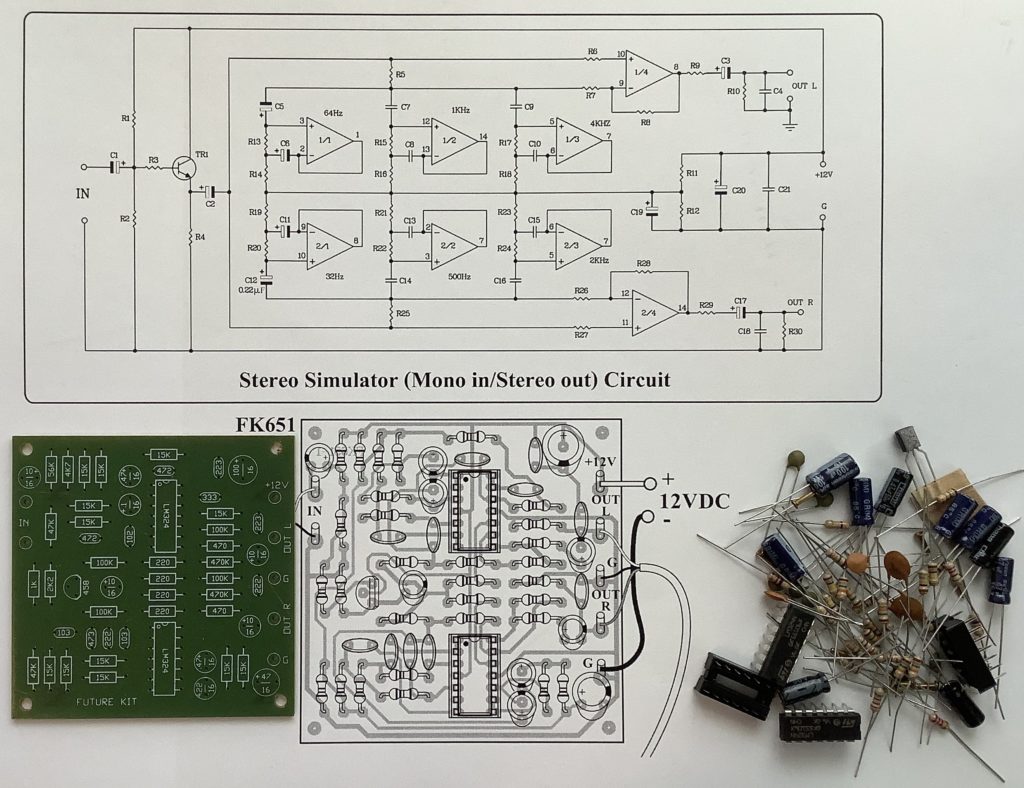
The FK651 takes a MONO signal, splits it, and sends each side into a short filter chain. The left and right filter chains have different peak frequencies:
    Right channel
    -------------
        32Hz  (Note C1)
        500Hz (Note C5)
        2kHz  (Note C7)
    Left channel
    -------------
        64Hz  (Note C2)
        1kHz  (Note C6)
        4kHz  (Note C8)
The filter chains alter each side of the stereo pair just enough to create the impression of different source signals coming from the right and left channels.
Kit of parts
The FK651 kit is fairly small making it suitable as a PSS-A50 mod. The small board should fit easily within the PSS-A50 even with the A50’s rather large speaker. I tested the FK651 with a 9V battery and it worked well even though 9V is below the suggested 12V supply voltage. I’m hoping to tap power from the A50’s 6V battery supply. Fingers crossed.

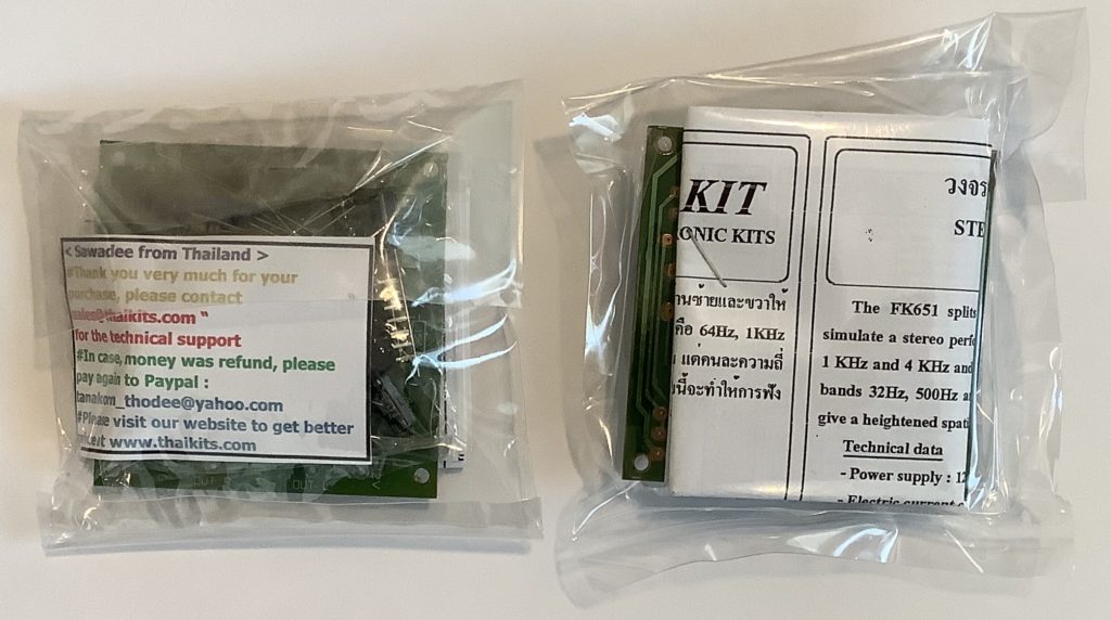
You’re not seeing double in the picture above. I ordered two FK651 kits. By the time I paid for one kit and shipping, it wasn’t much more to order two just in case I blew up a kit. It’s happened to me before, e.g., horribly destroying a Blokas MIDIboy during assembly.
Part and board quality are good.
Assembly
Assembly is straightforward. Given the number of parts, I assembled the kit in four phases:
- Resistors
- IC sockets and quad op amps
- Capacitors
- Wiring
Due to the placement of the power and audio pads, I couldn’t use terminal blocks. I decided not to use the enclosed terminal pins and soldered external connections directly to the printed circuit board (PCB).

There were two minor concerns. Although the printed directions are OK, the instructions do not include a resistor color code chart. If you decide to build an FK651 of your own, here’s my look-up chart.
Ohms Resistor color code---- ------------------------220 Red - Red - Brown470 Yellow - Violet - Brown1K Brown - Black - Red2K Red - Black - Red4.7K Yellow - Violet - Red15K Brown - Green - Orange47K Yellow - Violet - Orange56K Green - Blue - Orange100K Brown - Black - Yellow470K Yellow - Violet - Yellow
The second concern is a single inconsistency between the parts provided, the schematic, and a silk-screened legend on the PCB. [Does anybody use silk-screening anymore?] I found a 4.7K resistor when the PCB called for a 47K resistor. The part placement picture on the paper instructions has it right — “4K7”, the alternative way of writing “4.7K”. The PCB legend says “47K” and is wrong. Otherwise, it’s all pick, place and solder assembly.
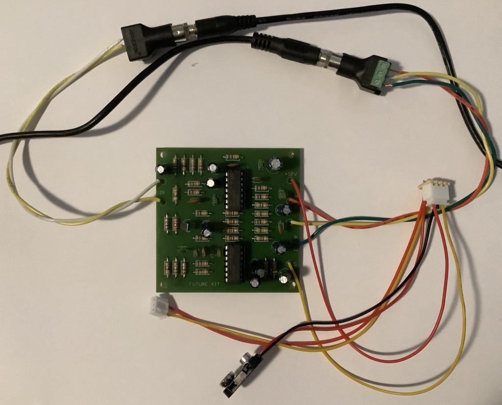
The picture above shows the completed board ready for testing. The audio wires come out to 3.5mm jacks with ring, sleeve, tip (RST) terminal blocks. This should make it easy to reconfigure the FK651 during bench experiments.
The power cabling may look unnecessarily complicated, but I decided to experiment in preparation for possible integration with the PSS-A50. The JST connectors should make for plug and play with the A50. The power wires solder into a tiny “distribution board” that I nibbled out of an old proto-board. The result is a tad ugly.
Use
Power up and the FK651 works the first time. 🙂
As to testing, perceived effect depends upon source material. I had reasonable success with a drum loop (WAV demo). The first half of the demo is the direct A50 audio and the second half is FK651 simulated stereo.
I applied the FK651 to a full mix (WAV demo). Again, the first half of the demo (about 10 seconds) is the direct A50 audio and the second half is simulated stereo. With the full mix, there is a clear difference between direct and effected. Whether it’s a stereo effect or not is subjective.
Clearly, the FK651 messes with the distribution of energy across the frequency spectrum. The effected full mix demo audio has less bass. As it is, the FK651 has a profound effect on a mix, maybe an unwanted effect that undoes your hard work balancing and mixing. The FK651 may be best applied to individual instruments, not a full mix.

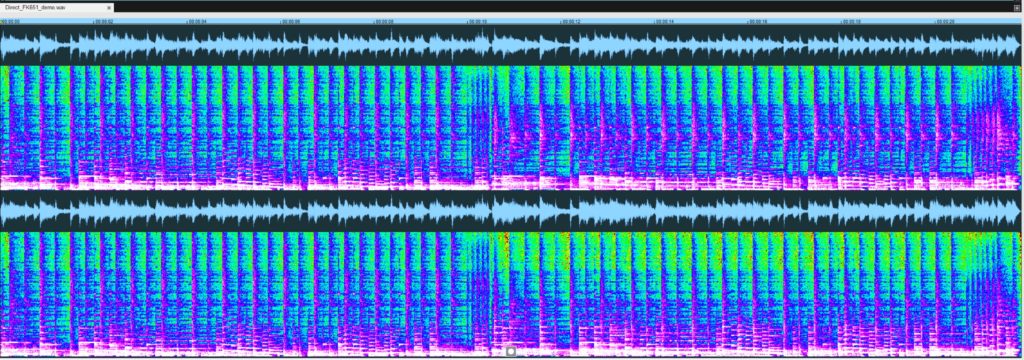
I experimented with ways to visualize the FK651 at work. Here is a false-color spectral plot for the full mix demo. The left and right channel plots are identical during the first half when the right and left channels each carry the same signal. During the second half of the demo, the right and left plots show differences due to the different filter chains applied to the left and right signals, respectively.
As to signal gain, boy, there is an abundance of gain! The A50 line OUT is the headphone OUT, which itself is a fairly hot signal. The FK651 adds even more gain. I had to attenuate source signals heavily in order to sample cleanly without distortion. I also had to carefully balance the level of the first and second halves of the demo to avoid the “louder is better” bias of human hearing.
There are still a few more experiments to try. First, it might be helpful to mix a little of the original source signal into both the right and left channels as a way to mitigate loss in specific frequency bands. This may also be a way to control the depth of the simulated stereo effect (dry plus wet). Another trick to try is putting delay on one of the outgoing channels to enhance the Haas effect.
All in all, the Future Kit FK651 Stereo Simulator is an easy build and a fun toy (tool). It’s not a be all or end all solution. The Volca Mix stereo spread effect beats the FK651 hands-down. The FK651, however, is small and inexpensive enough to deploy in a circuit mod as long as you can tame its gain.
Copyright © 2021 Paul J. Drongowski
