
This week I got rolling on my next MIDI project — a mini MIDI controller with two knobs (potentiometers) and two buttons. I intend to mount the electronics in a Hammond 1991XXBBK enclosure, also known as an (ABS) stompbox. Plastic is OK because the box will reside by the pitch and modulation wheels on the Yamaha PSR-S950 arranger workstation. The plastic is less likely to mar the finish of the keyboard. (I hate scratches.) The ultimate goal is to augment the real-time control provided by the wheels.
The area next to the wheels is fairly small and a stompbox fits into it neatly. A stompbox is a fairly small, shallow box, so I needed an Arduino-based prototyping board that fits into a small enclosure. I first consider an Arduino plus prototyping shield combo, but rejected that solution. The Arduino + shield stack fit into a standard Arduino enclosure about the same size as the 1991, however, the pad-per-hole layout would have made soldering a bear.
Enter the Spikenzielabs Prototino. The Prototino is roughly 2 1/8 inches by 2 7/8 inches in size, compatible with the 1991. Its prototyping area uses the more standard DIP layout with two and three hole pads. This layout is soldering friendly. About one third of the surface area is taken by a minimal Arduino implementation: an ATMega 328P, crystal, power regulation and ICSP/FTDI connections. The voltage regulator is optional and I elected to leave it off in favor of an external 5V center positive power adapter. Here’s a picture of the assembled Prototino before pots and switches.
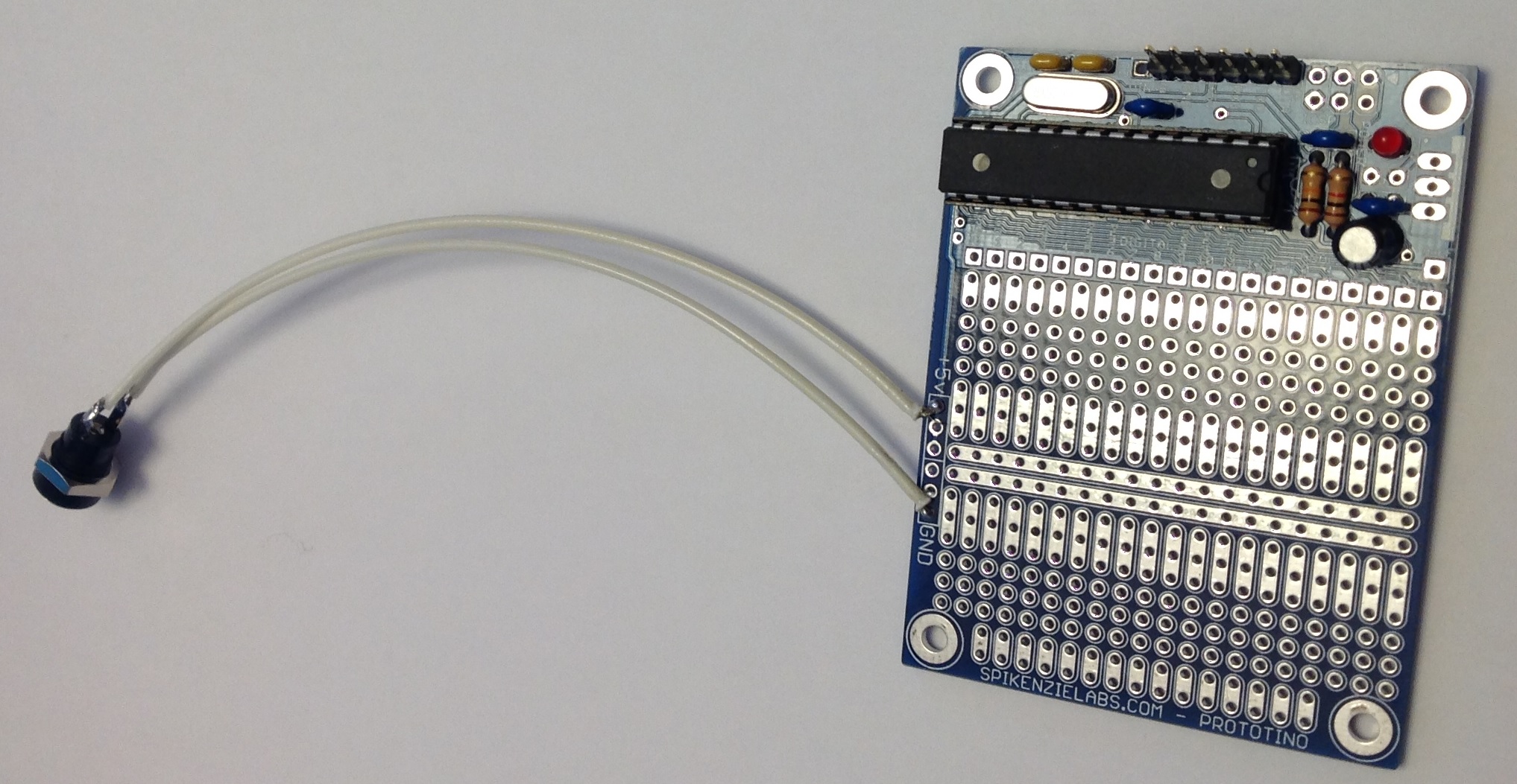
The connector at the end of the long tail is a 2.1mm power connector. This will eventually be mounted through a hole in the side of the 1991 enclosure along with a 3.5mm stereo jack for the MIDI OUT port.
The Spikenzielabs’ directions are decent enough, but here’s a few more tips. The directions identify the optional power components to be omitted during assembly. The directions do not mention where to make the +5VDC and ground connections, however. As you can see in the picture, power and ground are connected to the +5V and GND pads in the prototyping area.
The directions also describe how to connect the FTDI cable. I have a Sparkfun 5V FTDI cable and decided to go that route for programming. The directions are a little sketchy (no pun intended) on how to configure the IDE for the Prototino. This led to the usual scrambling around in the Device Manager, etc. when the IDE wouldn’t communicate with the Prototino. Yes, you do need to select the correct COM port. You also need to select the appropriate board. With the Sparkfun cable, choose “Arduino Pro or Pro Mini” from the list of boards. This always seems to be a hassle and probably puts off a lot of beginning makers.
Finally, now that the power light comes on and the sketch is downloaded, how do we really know that the Prototino is operating normally? A stock Arduino UNO, for example, has an LED tied to one of the pins and comes preloaded with the blink sketch to turn the LED ON and OFF. The Prototino just sits there. Fortunately, one can easily whip up a sketch that uses the serial port and serial port monitor to see if the Prototino is genuinely alive. The setup() function needs to turn on the serial port and display a message:
    Serial.begin(9600) ;
    Serial.println("Hello world.\n") ;
The loop function can do something playful, if you wish. Compile and download the sketch, then look for the output in the IDE’s serial port monitor.
Experience with the Prototino has been positive so far. I plan to mount pots and switches on the back side of the Prototino and to mount the Prototino to the lid of 1991 enclosure. This will let me connect the FTDI cable to the Prototino and program the device in situ. Stay tuned!