About pj

Now (mostly) retired, I'm pursing electronics and computing just for the fun of it! I'm a computer scientist and engineer who has worked for AMD, Hewlett Packard and Siemens. I also taught hardware and software development at Case Western Reserve University, Tufts University and Princeton. Hopefully, you will find the information on this site to be helpful. Educators and students are particularly welcome!

Winter NAMM 2019: Yamaha CP73 and CP88

As I mentioned in my last post, Yamaha have announced two new stage pianos: CP73 and CP88. Features in common are:

  • Three premium grand pianos: CFX, S700 and Bösendorfer Imperial 290
  • Two upright piano Voices: vintage U1 and flagship SU7
  • Five electric pianos for covering all music genres back to the 1970s
  • Yamaha CP OS updates enhance features and add new instrument Voices
  • CP OS v1.1 adds 67 Rd (Bright and Dark), Wide Wr & Yamaha C7 grand piano Voices
  • Dedicated effects and effect controls for each Section (Piano, E Piano and Sub)
  • Master delay, reverb and EQ effects with dedicated realtime controls
  • Soundmondo social sound sharing gives access to thousands of free sounds
  • Seamless Sound Switching: change sounds while holding notes without sound cutoff
  • One-to-one UI for direct sound control during stage or studio performance
  • 2 Ch. USB Audio/MIDI Interface for audio recording and playback & MIDI control
  • Balanced XLR & unbalanced 1⁄4” stereo outputs covers a wide-range of connectivity
  • Four-zone Master Keyboard mode lets you control external hardware and software
  • Dual 1/4″ AUX line inputs connects second keyboards, mobile devices and more

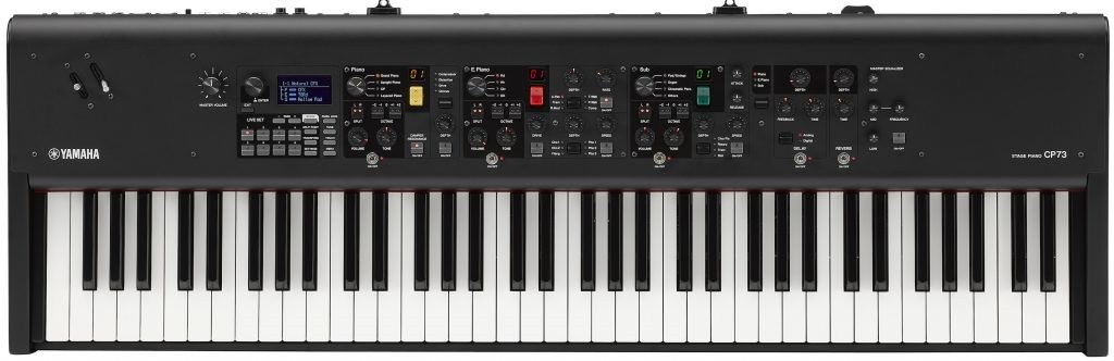
The CP88 has an NW-GH3 keyboard with synthetic ebony and ivory key tops and the CP73 has a balanced hammer 73-note action. The CP88 is 41 pounds while the CP73 is a lighter 28.9 pounds. How much is this going to set ya back? CP88: $2,499.99 and CP73: $1,999.99.

Here’s a link to the official Yamaha demo (no yakking).

Kraft Music has demo videos with no talking and a full demo with Blake Angelos. The Kraft demo shows off the CP73, which looks quite portable! The Sub adds a the usual pads, synths and things, but has its own tricks. In the non-talking demo, Blake shows off a “live looping” type performance at roughly 6:00. And, yes, the CP does B-3. Blake shows off “All Bars Out” starting at 8:30 with rotary speed changes.

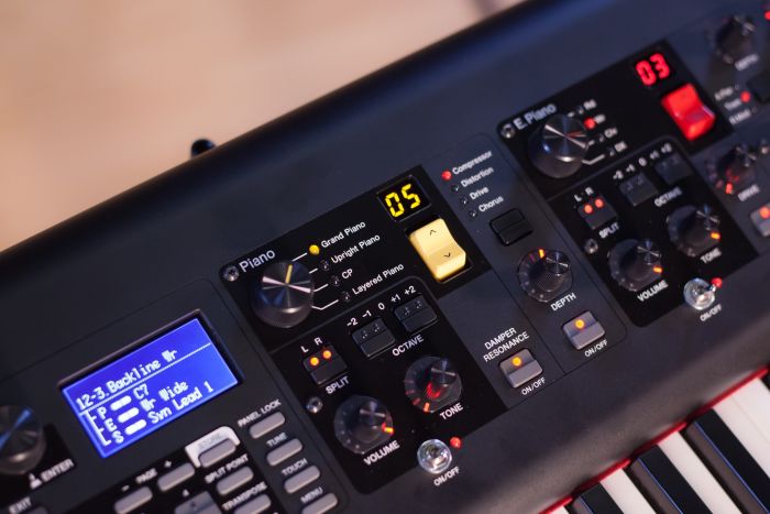
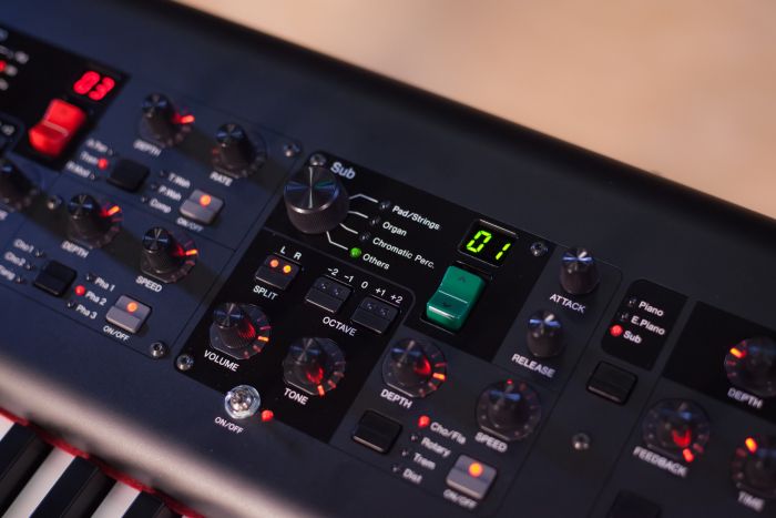
As I mentioned earlier, these instruments are built for pros. The acoustic pianos have wide dynamic range — no cheap out sampling. The chassis is sturdy aluminum. Both models provide balanced XLR outputs and internal power supply (no wall wart). The front panel interface is divided into sections: Live Set, acoustic piano, electric piano, sub and master. Each section is enabled by retro toggle switches. If you scan the front panel, there are lots and lots of (dedicated) digital effects. The sub section adds pad/strings, organ, chromatic percussion and other (bass, guitar, etc.). [Wish I knew what else is hiding under “other.”]

The auxiliary inputs do not route through the internal effects. Shame, lost opportunity, but could save hauling a separate mixer to small piano gigs. External audio can be routed through USB into the CP.

A big question is “Are the CP73 and CP88 Nord Stage killers?” Hmmm, no real-time drawbar control and no “mini synth” like the Stage. On the other hand, the CPs have Advanced Mode for creating novel instrument and effect routing (e.g., looping). Yamaha makes excellent, pro digital pianos (stage, studio, or home). So, if piano were my primary instrument, I would definitely have a fly-off between the CP and Stage before putting one on the credit card.

Copyright © 2019 Paul J. Drongowski

Winter NAMM 2019: Korg and more

Back on the streets at home just in time for Korg to drop its newest products. The details are up on the Korg Web site, so there isn’t a need to deep dive the details here.

The Kog Minilogue brings a smile to my face whenever I play it. Since I don’t have an actual need for it, “play it” means “noodle in the store.” However, it is a constant temptation for an impulse purchase.

Thus, I’m pleased to see a new model: the Korg Minilogue XD. Like its updates to the venerable microKorg, Korg are smart to pursue and extend winners. The XD keeps much of the basics intact. The front panel slider is now a joystick — a good change in my opinion. The XD adds a VPM (Variable Phase Modulation)/FM oscillator allowing two op FM voices. Memory is greatly expanded to 500 locations. And two control voltage (CV) inputs.

Expected street price is $650 USD. (The original model streets for about $520.)

Korg also dropped the Volca Modular. If you want to dip into synthesis, here’s your toy, er, tool: eight modules, 50 patch points, 16-step sequencer, “West Coast” style. Yeah, sure, Korg cut cost. The patch points are printed circuit board (PCB) mounted SIL and DIL connectors which take pin-style patch cables instead of 3.5mm plugs. But, wot did you expect for $200 street?

I have to wonder how the Volca Modular would mate to littleBits synth elements?

Finally, Korg revealed the Volca Drum digital percussion synthesizer. Bang on the drum all day with a 16-step sequencer and MIDI IN. Expected street price is $170 USD. Both Volcas will ship in early 2019.

Piano storm

It’s just rainin’ pianos up in here!

Casio have been teasing what could be a new stage piano. [I don’t do teasers any more.] Casio also have new CDP models: CDP-S100 and CDP-S350. “CDP” apparently means “Compact Digital Piano.” Both pianos feature new piano samples and the new Casio Scaled Hammer Action II Keyboard. The CDP-S100 and CDP-S350 have estimated street prices of $500 and $675, respectively. [I’m awaiting USA pricing.]

The CDP-S100 is aimed squarely at the cost conscious and portable Yamaha Piaggero series. The S100 has 64-note polyphony, ten voices, reverb/chorus, two built-in speakers, and battery power (six AA batteries). It weighs 10.5kg (23.1 pounds) and is quite slender. The speakers are front-firing a la the Studiologic NUMA Compact 2x.

The CDP-S350 takes a page from the Korg Havian playbook and the Yamaha DGX series by incorporating arranger keyboard features with a high quality piano. Quick specs include 64 note polyphony, 700 voices, 10 user songs, 200 rhythms (AKA “styles”), auto-harmonization, 100 arpeggios, and battery operation. Weight is 10.9kg (24 pounds). The S350 also employs built-in, front-firing speakers.

Yamaha are announcing the new CP73 and CP88 stage pianos, both clearly positioned to compete with Nord on-stage. The CP88 features Natural Wood Graded Hammer (NW-GH) action while the CP73 has 73 equally-weighted keys. Both axes have Yamaha’s best piano sounds: Yamaha CFX and Bösendorfer Imperial grands. Yamaha also got the message from pros: Seamless Sound Switching and XLR balanced outputs.

Taking a close look at the front panel, the new CPs offer three sound sections: acoustic piano, electric piano and “sub” from which one builds splits and layers. There are LIVE SET buttons to quickly change between configurations. Pitch bend and modulation control are through two levers located in the upper left corner of the work surface.

Like Nord, Yamaha are offering “content upgrades.” The first available sound upgrades include Rhodes (“1967 tine piano), Wurli (“reed piano”) and Yamaha C7 “studio” grand piano.

Expect $2,499.99 USD for the CP88 and $1,999.99 for the CP73. I find it interesting that the press release is out of Rellingen, Germany — home of the Genos™ and other Yamaha arranger products. Probably not significant.

Copyright © 2019 Paul J. Drongowski

Winter NAMM 2019: Interfaces

With 15 days until Winter NAMM 2019, no bombshell products other than unverified rumors on the forums. Here’s a few announced products which will be promoted at Winter NAMM 2019.

Inexpensive audio/MIDI interfaces

Readers of Sound On Sound may covet audio/MIDI interfaces with 4 figure price tags, but it’s the low end of the price spectrum for us punters.

PreSonus have a handsome product in the PreSonus Studio 2|4. Just the facts:

  • Preamps: PreSonus XMAX-L solid-state preamps
  • Sample rate: 44.1, 48, 88.2, 96, 176.4, or 192 kHz
  • Resolution: 24-bits
  • ADC dynamic range: 108 dB
  • DAC dynamic range: 108 dB
  • Audio inputs: 2x combo front panel, +48V phantom power
  • Audio out: 2x 1/4″ TRS rear panel
  • MIDI: IN and OUT rear panel
  • Headphone out: 1/4″ TRS rear panel
  • USB: USB-C rear panel
  • Software bundle: Studio One Artist
  • Street: $149.99 USD

Front panel controls include input levels, mix, main and headphone out. One advantage over the Mackie (our next contender) is front panel metering: inputs and main.

Mackie are offering a pair of ONYX Series interfaces: Onyx Artist 1•2 and Onyx Producer 2•2. By way of comparison, specs for the Onyx Producer 2•2 are:

  • Preamps: Mackie Onyx mic preamps
  • Sample rate: Up to 192 kHz
  • Resolution: 24-bits
  • Audio inputs: 2x combo front panel, +48V phantom power
  • Audio out: 2x 1/4″ TRS rear panel
  • MIDI: IN and OUT rear panel
  • Headphone out: 1/4″ TRS front panel
  • USB: USB 2.0 rear panel
  • Software bundle: Traktion T7 plus 16 FX plug-ins
  • Street: $179.99 USD

Mackie claims that they are “built-like a tank.” Given that my old 1202 mixer is still in service, they mean it. Front panel controls include input gain, mix, monitor and headphone levels.

Given the price points and feature set, comparison is irresistable. For the money, I’d go with the PreSonus: USB-C, front panel metering and lower street price. I’ve been using the same trashed out MIDI and audio interfaces for a looong time. Maybe upgrade? The PreSonus does look nice.

Roland GO:PIANO88

My review of the Roland GO:KEYS is one of the most often viewed articles on this site. It’s a neat inexpensive keyboard and I’ll bet that the GO:PIANO is just as popular, especially with parents who want to get their kids started with a musical instrument.

Roland have extended the GO:PIANO line with an 88-key model — the Roland GO:PIANO88. It’s still quite portable (7kg), does Bluetooth, and runs on (optional) battery power. Roland are pitching this product squarely at the entry home and education markets. Street price is $399.99 USD.

Other GO:PIANO88 specs include: Four tones (piano, EP, organ, strings), reverb, 128 voice polyphony, 2 x 10W amplifier power, 15 x 6 cm speakers, pedal in, headphone out and USB Micro-B for MIDI. GO:PIANO88 also features Amazon Alexa voice control. What would Alexa say to a whinging kid who doesn’t want to practice? 🙂

My chief reservation about the GO:KEYS and GO:PIANO is quality and feel of the keybed. I hope that Roland has made improvements. Roland describe the keys as “Box-shape Keys with velocity.” Definitely not hammer-action.

BTW, what’s up with all of the punctuation characters in product names? Vertical bars? Dots? Colons? Cheesh.

Copyright © 2019 Paul J. Drongowski

Noted in passing

A recent post about the Venova™ wind instrument reminded me about a few patent applications from last summer.

In addition to technology patents, Yamaha have been actively filing for and obtaining design patents on the physical industrial design of their products. Here are a half-dozen recently awarded design patents:

When I first saw the Venova, I thought, “Man, that looks like the physical manifestation of a virtual VL wind instrument.” Yamaha filed two patent applications for both the Venova and a close cousin: US Patent Application 2018/0254026 and 2018/0190245. If you’re interested in the gory details about the Venova design, dig in.

Ah, physics.

Copyright © 2019 Paul J. Drongowski

Genos to 60 in 4 seconds

Well, maybe two minutes. 🙂 Let’s say that you want to use Yamaha Genos™ solely as a synthesizer. Here’s a quick start or at least enough to get you familiar enough to get into the Owner’s Manual.

Turn accompaniment off

If you want to use Genos as a synth, I recommend turning the accompaniment features off. Accompaniment is all the AUTO stuff including styles, rhythm pattern and such. Press the ACMP button in the left hand corner of the front panel. If the light is off, accompaniment is off.

Select a new voice

When you power on Genos, you’ll see the HOME screen as shown below. [Click images to enlarge.]

The HOME screen is a top-level view of Genos’ current configuration. From here, you can select a voice for each of Genos’s Parts: LEFT, RIGHT1, RIGHT2, and RIGHT3. (More about this in a second or two.)

Touch the big square button for the CFX Concert Grand. In response, Genos displays the voice selection screen. The Part (RIGHT1) is shown in the upper left corner of the screen. Use the soft buttons on the left hand side of the screen to select a voice category. Then use the tabs (P1, etc.) to navigate through pages and pages of available instruments. Touch the instrument that you want to assign to the Part.

In the example above, I touched the Woodwind button, went to page 3 (P3) and selected the MOR Oboe voice. If you press the nice bright HOME button on the front panel (located just to the right of the screen), Genos will display the HOME screen and you will see the MOR Oboe voice assigned to RIGHT1. Those six bright gateway buttons are the most important shortcuts into the Genos menu system.

Parts is parts

The LEFT, RIGHT1, RIGHT2 and RIGHT3 business is a cut-down form of (Yamaha) synth parts and zones. Unlike a synth where you can create arbitrary keyboard zones, splits and layers, the Yamaha arranger concepts are more limited.

Each of LEFT, RIGHT1, RIGHT2 and RIGHT3 are voice parts which can be turned on and off. There are four voice select buttons and four voice on/off buttons in the lower right hand corner of the front panel. The voice select buttons choose the current Part for editing, etc. The voice on/off buttons turn the voice on and off, letting one add or remove a voice while playing.

LEFT, RIGHT1, RIGHT2 and RIGHT3, from the synth perspective, are also keyboard zones. In terms of voice splits, you can have a single left hand voice (LEFT) and up to three layered right hand voices (RIGHT1, RIGHT2 and RIGHT3). If you’re playing with accompaniment styles, chord recognition is often in the left hand and melody/comping is in the right hand. (This is a gross simplification; Genos has more capability for chord recognition than this.)

The screen shot below shows one of my orchestral splits. There is a cello in the left hand and there is an oboe plus flute layer in the right hand.

Ordinarily, the the split point is middle C. If you want to change the split point (and other aspects of the key layout), press the MENU gateway button on the front panel. Genos displays a page of buttons that lets you tweak tempo, transpose, MIDI, split point and fingering, and just about everything else which is Genos.

Touch the Split & Fingering button and Genos displays the screen giving control over the split point.

Press the arrow buttons to move the split point(s) around. Or, press and hold one of the three soft buttons on the left hand side of the screen. While holding one of those buttons, press the desired split point on the keyboard.

A word of caution — watch out for the RIGHT3 split point. Genos offers a little more flexibility for the RIGHT3 zone than the simple scenario that I’ve described here. Please see the Owner’s Manual page 49 for more details. Sometimes the RIGHT3 setting causes confusion. (Why don’t I hear…?)

How to remember settings

Now that you have a voice set-up, you’ll want to remember it. Genos remembers such things in registrations. A registration is a memory location that remembers all sorts of fun stuff: the current voices, the current style, tempo, MIXER settings, etc. The Owner’s Manual Chapter 7 goes into registrations in detail.

To save the current configuration, press the MEMORY button on the front panel. Then press one of the ten numbered registration buttons. The current configuration will be saved to that location (button).

Even though it’s beyond the scope of a two minute introduction, the ten registrations taken together constitute a registration bank. Genos can save and recall banks. I strongly recommend saving the entire bank to either the Genos internal memory or to a USB flash drive. Otherwise, it’s all to easy to lose your work by overwriting a button!

Extra credit

Keen eyed readers probably noticed the words “MIXER settings.” Yep, Genos has an on-screen mixer for balancing levels and other tweaks. Press the soft Mixer button at the bottom of the HOME screen to see more. BTW, when I use Genos as a synth, I set the STYLE level to zero in the MIXER. I’m paranoid and don’t want any unintended and unwanted auto accompaniment triggered when I’m playing Genos purely as a synth.

If you don’t want to deal with the MIXER, then grab those sliders and knobs! The LIVE CONTROL screen shows the currently assigned knob and slider parameters. The OLED display switches between slider and knob values whenever a slider or knob is moved. Use the KNOB ASSIGN and SLIDER ASSIGN front panel buttons to flip through parameter groups. The groups are configurable, but that is way beyond extra credit.

The Voice Part Setup screen is another way to tweak. Press the front panel VOICE gateway button. Genos displays the Voice Part Setup screen (below).

Here, you can turn Parts (voices) on and off, set levels, set pan, change the octave range, and change the DSP effect assigned to the voice. Peek and poke away!

Copyright &copy 2019 Paul J. Drongowski

Zoom Q2n-4K: Wow!

January 2nd and I’ve started my Web-scrape in advance of Winter NAMM 2019 (24-27 January 2019).

I came across a short blurb for the Zoom Q2n-4K Camera for Musicians and all I can say is “Wow!” A lot of this “Wow” comes simply from my awe at the amount of high definition functionality — video and audio — which can be packed into a small package. Oh, yeah, for $199USD:

  • Image Sensor: 1/2.3″ 16 M-flexible CMOS sensor
  • Video resolution: 4K, 1080, 720
  • Audio Formats: WAV: 96 kHz/24-bit, 48 kHz/24-bit, 44.1 kHz/16-bit
  • Display: 1.77″ four-color LCD (160 × 128)
  • Built-in Mic: Fixed 120° XY stereo mic
  • Video out: HDMI micro Type D
  • Power: 2 AA batteries or adapter

If the Q2n-4K was available in the 60s and 70s, you could have shot it to the moon on a robotic lander (issues of radiation hardening and temperature extremes aside). It would have exceeded anything available at the time for resolution, weight and power.

I may have to give the Q2n-4K a try as my trusty Roland Micro-BR is getting long in the tooth. It would make a handy recorder on Sundays when I’d like to record our music ministry in action for self-critique.

Then there is the Zoom H3-vr recorder with 4 built-in mics arranged in an Ambisonic array (below).

Take me to your leader. Take me to your leader.

It’s amazing to see and hear where 60+ years of solid state electronics has gotten us…

Copyright © 2018 Paul J. Drongowski

Crumar D9U: Electro 2 Sketch (Part 5)

Finally, after all of the testing, the first Crumar D9U Drawbar Controller application sketch! The sketch below changes the drawbar settings for the Nord Electro 2. The Arduino on board the D9U sends a complete snapshot of all nine drawbar settings to the Electro 2 at start-up and whenever the tactile switch is depressed. Thereafter, it sends a MIDI message to the Electro 2 whenever a slider (drawbar) is changed.

The sketch drives only the Electro 2 upper drawbars. If you need the lower drawbars, too, you can follow Crumar’s example sketch and extend my sketch.

The sketch does not use the Arduino MIDI library because we only need to send simple MIDI continuous control (CC) messages. It’s easy enough to write the necessary code ourselves.

I encountered an Arduino compiler toolchain issue while developing the sketch. I wasn’t able to initialize snapCount in the setup() function. I’ll work around this issue in future sketches and you should back-port the fix. It’s not the first time that I’ve run into an Arduino toolchain bug…

The program logic is quite simple. There are three helper functions: sendNoteOn(), sendNoteOff(), and sendMidiCC(). The sketch uses only the third function which sends a MIDI continuous control message through the Serial1 port, i.e., the Arduino Leonardo TX pin.

The setup() function initializes the digital pins and global variables, and calls sendSnapshot() to scan the analog pins, sending a MIDI CC message for each drawbar. The idea is to sync the Electro 2 with the D9U when the D9U is turned on. You should select an organ voice on the Electro 2 before turning on the D9U in order to take advantage of this feature.

The loop() function goes round and round. If the tactile switch is depressed, the sketch takes a snapshot of the analog pins (sliders) and sends a MIDI CC message for each slider (drawbar). The variable snapCount debounces the tactile switch input, preventing a flood of MIDI CC messages to MIDI OUT and the Electro 2.

After checking the tactile switch, the loop() function delays for a short time and then calls checkSliders(). The function checkSliders() keeps a copy of the most recent slider values. When it detects a change, it saves the new slider value and sends a MIDI CC message with the new value. The Electro 2 accepts drawbar values over the range from 0 to 127.

It’s rather gratifying to attach the Crumar D9U to the Electro 2 and watch the Electro’s drawbar status lights change in sync with the D9U drawbars. Cool. Fun to play, too.

If you have a Nord Electro 2 and a D9U, enjoy the sketch!

Copyright © 2018 Paul J. Drongowski

/*
 * Electro2.ino: Crumar D9U sketch for Nord Electro 2
 */

/*
 * Author:  P.J. Drongowski
 * Address: http://sandsoftwaresound.net/
 * Date:    12 December 2018
 * Version: 1.0
 *
 * A simple sketch to control the Nord Electro 2 with the
 * Crumar D9U Drawbar Controller. This sketch controls
 * the upper drawbars, but could be extended to control
 * the lower drawbars. See the Crumar sketch for
 * inspiration!
 *
 * We assume a direct 5-pin MIDI connection from the
 * D9U to the Electro 2. Since direct MIDI is so simple,
 * the sketch does not use the Arduino MIDI library.
 * MIDI bytes are sent using Serial1.write().
 *
 * Send on MIDI CC messages on MIDI channel 0.
 *
 * Electro 2 MIDI continuous controllers (CC) are:
 *    Parameter       Upper CC#  Lower CC#
 *    --------------  ---------  ---------
 *    16' drawbar         16        70
 *    5 1/3' drawbar      17        71
 *    8' drawbar          18        72
 *    4' drawbar          19        73
 *    2 2/3' drawbar      20        74
 *    2' drawbar          21        75
 *    1 3/5' drawbar      22        76
 *    1 1/3' drawbar      23        77
 *    1' drawbar          24        78

 */

// Pin definitions
#define LED_RED    15
#define LED_GREEN  16
#define BUTTON     5

// Analog pin map
#define NUMBER_OF_SLIDERS 9
int AnalogPinMap[NUMBER_OF_SLIDERS] = {
  A0, A1, A2, A3, A6, A7, A8, A9, A10
} ;

// Drawbar to MIDI CC# map
int MidiCCMap[NUMBER_OF_SLIDERS] = {
  16, 17, 18, 19, 20, 21, 22, 23, 24
} ;

// Global variables
int sliders[NUMBER_OF_SLIDERS] ;
#define SNAP_COUNT  (200)
int snapCount = SNAP_COUNT ;

// MIDI channel
#define CHANNEL 0

// Bias offset for incoming slider values [unused]
#define BIAS 32

void sendNoteOn(byte pitch, byte velocity) {
  Serial1.write(0x90 | CHANNEL) ;
  Serial1.write(pitch) ;
  Serial1.write(velocity) ;
}

void sendNoteOff(byte pitch) {
  Serial1.write(0x80 | CHANNEL) ;
  Serial1.write(pitch) ;
  Serial1.write(0) ;
}

void sendMidiCC(byte cc, byte value) {
  Serial1.write(0xB0 | CHANNEL) ;
  Serial1.write(cc) ;
  Serial1.write(value) ;
}

// Take a snapshot of the current slider state and
// send MIDI CC for all sliders. Electro 2 CC value range
// is 0 to 127.
void sendSnapshot() {
  int newValue = 0 ;
  for (int i = 0 ; i < NUMBER_OF_SLIDERS ; i++) {
    newValue = (analogRead(AnalogPinMap[i]) & 0x3FF) / 8 ;
    sliders[i] = newValue ;
    sendMidiCC(MidiCCMap[i], newValue) ;
  }
}

// Check the sliders for movement (changes). When a change
// is detected, send a MIDI CC message. Nord Electro CC
// values range from 0 to 127.
void checkSliders() {
  int newValue = 0 ;
  for (int i = 0 ; i < NUMBER_OF_SLIDERS ; i++) {
    newValue = (analogRead(AnalogPinMap[i]) & 0x3FF) / 8 ;
    if (sliders[i] != newValue) {
      sliders[i] = newValue ;
      // Send MIDI CC message when the value changes
      sendMidiCC(MidiCCMap[i], newValue) ;
    }
  }
}
 
void setup() {
  // Set up pins
  pinMode(BUTTON, INPUT_PULLUP) ;
  pinMode(LED_RED, OUTPUT) ;
  pinMode(LED_GREEN, OUTPUT) ;

  // Set up Serial1 for MIDI via TX and RX (31,250 baud)
  Serial1.begin(31250) ;

  // Initialize the button debounce count
  // Send an initial snapshot. This operation initializes
  // the current slider values, too.
  sendSnapshot() ;
}

void loop() {
  if ((digitalRead(BUTTON) == LOW) && (snapCount <= 0))
  {
    // Take and send a snapshot of the sliders
    sendSnapshot() ;
    snapCount = SNAP_COUNT ;
  } else {
    snapCount-- ;
  }

  delay(1) ;
  checkSliders() ;
}

Crumar D9U: Testing MIDI (Part 4)

Apologies for the delay between posts. It isn’t for lack of enthusiasm for the Crumar D9U Drawbar Controller. It’s preparation for the approaching holidays.

Today’s post is another aspect of unit testing — MIDI. The D9U has a 3.5mm MIDI OUT jack. The MIDI signals conform to the MIDI “Type B” pin-out for 3.5mm jacks. The Type B pin-out is:

    DIN      3.5mm
    -----    --------------------
    Pin 4    Tip (Current Source)
    Pin 5    Ring (Current Sink)
    Pin 2    Sleeve (Shield) 

Type B is used by Arturia, Novation, and 1010Music.

I must note that the MIDI “Type A” pin-out is going to be the standard going forward. Unfortunately, the MIDI Association didn’t get ahead of manufacturers when they began using 3.5mm jacks. For reference, the Type A pin-out is:

    DIN      3.5mm
    -----    --------------------
    Pin 4    Ring (Current Source)
    Pin 5    Tip (Current Sink)
    Pin 2    Sleeve (Shield) 

Type A is used by Akai Pro, IK Multimedia, Korg, Line 6, littleBits, and Make Noise. I found the chart below to be quite helpful in running down an appropriate adapter cable. (Source: MIDI Association 3.5mm stereo TRS to MIDI 5-pin DIN cables)

Thanks to all of the Christmas prep, I didn’t miss a step while waiting for the 1010Music adapter to arrive. (It’s Advent after all.) I detest making cables and the 1010Music adapter is reasonably priced.

I also got down to work on a MIDI test sketch for the D9U. (Code appears at the end of this post.) The sketch does not use the Arduino MIDI library because it simply sends MIDI note ON and note OFF messages through the MIDI port.

If you’re new to Arduino Leonard — the D9U’s Pro Micro is a Leonardo — you may not know that Leonard has two serial ports: Serial and Serial1. The first port, Serial is dedicated to USB communications. The second port, Serial1, is dedicated to the digital RX and TX pins, similar to Arduino UNO, et al. The naming convention sometimes confuses coders who are new to Leonardo. In our case, when we want to send MIDI, we use the Serial1 port, which must be configured for the MIDI baud rate, 31,250Hz.

The sketch repeatedly sends MIDI note ON and OFF messages such that you should hear a steady series of staccato notes when the MIDI message stream is sent to a tone generator. In my case, I connected the D9U to my trusty Yamaha QY70 sequencer and tone module.

Here’s another little twist. Leonardo is equipped with two additional LEDs: TXLED and RXLED. These LEDs flash when there is transmit and receive activity (respectively) on the USB port. The test sketch does not use the USB port (Serial), so the TXLED and RXLED are ours to play with. The four macros:

    TXLED0 ;      RXLED0 ;
    TXLED1 ;      RXLED1 ;

control the LEDs. If you compile the sketch on a regular Arduino (e.g., UNO), these macros will be flagged as undefined symbols.

Extra credit

While wading through the Type A vs. Type B nonsense, I did a few simple experiments with the D9U’s MIDI port. For example, you can check the signal levels using a digital multimeter. DIN pin 2 should read as 0 Volts (ground) while DIN pin 4 should be +5 Volts. DIN pin 5 is the data pin which pulls the MIDI current loop to ground. Please remember that MIDI is a current loop where:

  • Logic 1 → High → no current flow → Opto-isolator LED off → MIDI receiver sees High, logic ‘1’ (data bits, stop bit or idle)
  • Logic 0 → Low → current loop flow rarr; Opto-isolator LED on → MIDI receiver sees Low, logic ‘0’ (data bits, start bit)

Thanks, Wikipedia.

The sender (MIDI OUT) turns an LED on and off in the receiver (MIDI IN). The LED is part of an opto-isolator which provides electrical isolation between the sender and the receiver.

So, if you want to check out MIDI signals at the pins, all you need is an LED and a current limiting resistor (e.g., 330 ohms) in series in the current loop. The LED lights when connected in the direction of positive current flow. Here are my handwritten notes.

David Battino would be proud. David loves to add flashing LED eyes to Japanese movie monster toys and more. One of these days I’ll put all of those Godzillas in our basement toy chest to work. 🙂

Copyright © 2018 Paul J. Drongowski

/*
 * MidiTest.ino: Crumar D9U MIDI and slider test
 */

/*
 * Author:  P.J. Drongowski
 * Address: http://sandsoftwaresound.net/
 * Date:    11 December 2018
 * Version: 1.0
 *
 * This test reads the current slider values. If there is a
 * change, it prints the current slider values to the Arduino
 * serial port. Watch the values change in the IDE's Serial
 * Monitor. The incoming slider values are biased so that
 * values range reliably from 0 to 8. (Leonarkdo's Serial
 * port is dedicated to USB communications.
 *
 * Additionally, send MIDI note ON and note OFF messages to
 * the Serial1 port. On Leonardo, Serial1 communicates via
 * the TX and RX pins.
 */

// Pin definitions
#define LED_RED    15
#define LED_GREEN  16
#define BUTTON     5

// Analog pin map
#define NUMBER_OF_SLIDERS 9
int AnalogPinMap[NUMBER_OF_SLIDERS] = {
  A0, A1, A2, A3, A6, A7, A8, A9, A10
} ;

// Global variables
int colorMode = 0 ;
int ledMode = 0 ;
int noteState = 0 ;
int sliders[NUMBER_OF_SLIDERS] ;

// Bias offset for incoming slider values
#define BIAS 32

void sendNoteOn() {
  Serial1.write(0x90) ;
  Serial1.write(36) ;
  Serial1.write(100) ;
}

void sendNoteOff() {
  Serial1.write(0x90) ;
  Serial1.write(36) ;
  Serial1.write(0) ;
}

void changeColors() {
  if (colorMode) {
    digitalWrite(LED_RED, LOW) ;
    digitalWrite(LED_GREEN, HIGH) ;
  } else {
    digitalWrite(LED_RED, HIGH) ;
    digitalWrite(LED_GREEN, LOW) ;
  }
}

void printSliders() {
  for (int i = 0 ; i < NUMBER_OF_SLIDERS ; i++) {
    Serial.print(sliders[i]) ;
    Serial.print(" ") ;
  }
  Serial.println("") ;
}

void checkSliders() {
  int changeFlag = 0 ;
  int newValue = 0 ;
  for (int i = 0 ; i < NUMBER_OF_SLIDERS ; i++) {
    newValue = (analogRead(AnalogPinMap[i]) + BIAS ) / 128 ;
    if (sliders[i] != newValue) {
      changeFlag = 1 ; 
      sliders[i] = newValue ;
    }
  }
  if (changeFlag != 0) {
    // If a change was made, print current slider values
    printSliders() ;
  }
}
 
void setup() {
  // Set up pins
  pinMode(BUTTON, INPUT_PULLUP) ;
  pinMode(LED_RED, OUTPUT) ;
  pinMode(LED_GREEN, OUTPUT) ;

  // Set up Serial1 for MIDI via TX and RX (31,250 baud)
  Serial1.begin(31250) ;

  colorMode = 0 ;
  noteState = 0 ;

  for (int i = 0 ; i < NUMBER_OF_SLIDERS ; i++) {
    sliders[i] = -1 ;
  }
}

void loop() {
  if (digitalRead(BUTTON) == LOW) {
    colorMode = 0 ;
  } else {
    colorMode = 1 ;
  }

  // Make the TX and RX LEDs flash in sync with the notes.
  // The TX and RX LEDs are Leonardo only. Remove the code
  // below when compiling for Arduino UNO, etc.
  if (ledMode) {
    ledMode = 0 ;
    TXLED1 ;
    RXLED0 ;    
  } else {
    ledMode = 1 ;
    TXLED0 ;
    RXLED1 ;
  }
  
  if (noteState != 0) {
    sendNoteOn() ;
    noteState = 0 ;
  } else {
    sendNoteOff() ;
    noteState = 1 ;
  }

  delay(100) ;
  changeColors() ;
  checkSliders() ;
}

Crumar D9U: What went wrong? (Day 3)

People who build stuff are optimists. Even just a little.

After slaving over a hot soldering iron (or bit of code), there comes the moment of truth. Of course, we all hope and believe that everything will run just fine when power is turned on.

Thus, I was a little bit bummed when I ran my drawbar test sketch (Arduino program) and saw that the second drawbar was unresponsive.

Hey, PJ, how did you debug and fix this thing?

First and foremost, I want to emphasize the importance of diagnostic tests. My test sketch told me conclusively that the second drawbar was busted. The test not only said, “Houston, we have a problem,” but the test also told me where to look for the problem — the second drawbar. Explicit testing is much better than trying to test and debug hardware with the application sketch itself, i.e., the sample sketch provided by Crumar.

Knowing that the second drawbar was bunged, I whipped out my digital multimeter and did a few simple electrical tests. I usually assume good components, but it was easy to check the second slide pot. Yep, the meter read out the expected resistance. Then I did quick continuity and resistance checks back to the appropriate Arduino analog pin. Thank heavens for the sample sketch because I quickly worked out the pin map (Arduino Pro Micro):

          TX o    o RAW
          RX o    o GND
         GND o    o RST
         GND o    o VCC
         SDA o    o A3    Draw4
         SCL o    o A2    Draw3
  Draw5   A6 o    o A1    Draw2  <---
             o    o A0    Draw1
  Draw6   A7 o    o SCLK
             o    o MISO
  Draw7   A8 o    o MOSI
  Draw8   A9 o    o A10   Draw9

I numbered the drawbars (left to right) starting with one. The Crumar schematics numbers the drawbars from zero. [Oh, well.]

This was a good time to check the batteries in the multimeter. Whoops, 2017. Good, fair or poor, I replaced the batteries with fresh ones.

I didn't find anything out of the ordinary, so I began the usual prayer, "Dear Lord, I hope I didn't blowed up the chip." I did not relish the thought of replacing the Arduino Pro Micro -- all 24 pins of it.

My soldering skills are good, but not perfect. Plus, the large holes and the excessive amount of solder consumed by the slide pot leads immediately made me suspect a bad soldering joint.

In order to test this theory, I tried jumpering the voltage from the first drawbar slider to the Arduino A1 pin while watching the sketch's output in the IDE Serial Monitor. Perhaps an internal pull-up (or something) didn't change the A1 signal or the output from the sketch.

Then it was time to play "which of these isn't like the others" with the multimeter and with the power on. Ah-ha. The voltage at the SIGN #2 pad did not change when sliding the pot to a new position. The rest of the SIGN pads responded correctly. Not conclusive evidence for a bad solder joint, but more hope than a blown up Arduino.

The next step was to fire up the iron and retouch the pot leads for the second drawbar. It takes longer for the iron to heat up than to do the touch up. Damn, these leads suck down solder.

After letting things cool, I plugged the Arduino back in and voila, the second drawbar now responds correctly. Thank you, test sketch.

When testing pot resistance, I noted some variability in resistance across the 9 pots. I hope the variability doesn't affect behavior when I get down to transmitting MIDI values. Maybe everything will act like a well-worn B3? Sometimes higher resistance is due to a marginal solder joint, but I'm not anxious to touch up every pot connection lest I introduce a worse problem. More testing ahead.

If you landed here, check out Day One in this series of blog posts about the Crumar D9U Drawbar Controller kit.

Copyright © 2018 Paul J. Drongowski

Crumar D9U: Slip slidin’ (day 2)

Today I completed most of the remaining assembly of the Crumar D9U Drawbar Controller. The work entailed:

  1. Combining the Arduino control board and the main PCB.
  2. Installing the drawbar slide pots on the bottom of the chassis.
  3. Soldering the main PCB to the slide pots and soldering the DIL connections to the Arduino control board.
  4. Installing colored plastic caps on the drawbars.

Overall, the work went well. Here’s a few observations and tips.

  • When the instructions say make the DIL flat and straight on the control board, they really mean it! The receiving holes on the main PCB are quite small and if that DIL isn’t straight, good luck. Even with a straight DIL, it took some finagling to pass the pins through the holes.
  • The control board and main PCB are joined by two long-ish bolts with spacers between the boards. The nuts are really tight. You will not be able to hold the nuts in place with fingers alone. I used needle nose pliers to hold the nuts while turning the bolts. Be careful not to damage the Arduino when using the pliers. I did bend a pin.
  • Experience with the main PCB and the slider pins was similar although these holes are larger and more accommodating. Gently straighten any bent pins.
  • Speaking of large holes, crimp the pot leads against the main PCB pads to make good electrical contact. These holes eat solder like crazy. You should rely on the solder to maintain electrical contact, not to be the electrical bridge itself.
  • The colored caps fit OK, but you will need to use a far bit of force to drive the screws into the caps for a firm result. The white knobs still have a tiny amount of play, but I was afraid to over-tighten the screws and strip the plastic.

The D9U is built like a warship although the tight fit of nuts and screws makes for a slightly stressful assembly job.

I forget to suggest one tip in yesterday’s blog post. If you have a breadboard available, it makes a nice jig for installing DILs and other components that you need to keep straight. Push the DIL into the breadboard, lay the board on top, and then solder away. I usually try to tack one or two corners first and then check for straightness, etc. If the DIL ain’t straight, it’s a lot easier to remove the tack from two pins (using a solder sucker or braided copper tape) than to remove solder from all 16 pins!

See my first blog post about the D9U for pictures of the pieces and parts in the kit.

Slider test sketch

Here is the code for a quick slider test. It prints the slider values to the Arduino IDE’s Serial Monitor. This sketch is already earning its keep — the second drawbar slider is not changing. The other eight sliders are changing just fine. I have some hardware debugging to do!

/*
 * SliderTest.ino: Crumar D9U initial test
 */

/*
 * Author:  P.J. Drongowski
 * Address: http://sandsoftwaresound.net/
 * Date:    7 December 2018
 * Version: 1.0
 *
 * This test reads the current slider values. If there is a
 * change, it prints the current slider values to the Arduino
 * serial port. Watch the values change in the IDE's Serial
 * Monitor.
 */

// Pin definitions
#define LED_RED    15
#define LED_GREEN  16
#define BUTTON     5

// Analog pin map
#define NUMBER_OF_SLIDERS 9
int AnalogPinMap[NUMBER_OF_SLIDERS] = {
  A0, A1, A2, A3, A6, A7, A8, A9, A10
} ;

// Global variables
int colorMode = 0 ;
int sliders[NUMBER_OF_SLIDERS] ;

void changeColors() {
  if (colorMode) {
    digitalWrite(LED_RED, LOW) ;
    digitalWrite(LED_GREEN, HIGH) ;
  } else {
    digitalWrite(LED_RED, HIGH) ;
    digitalWrite(LED_GREEN, LOW) ;
  }
}

void printSliders() {
  for (int i = 0 ; i < NUMBER_OF_SLIDERS ; i++) {
    Serial.print(sliders[i]) ;
    Serial.print(" ") ;
  }
  Serial.println("") ;
}

void checkSliders() {
  int changeFlag = 0 ;
  int newValue = 0 ;
  for (int i = 0 ; i < NUMBER_OF_SLIDERS ; i++) {
    newValue = analogRead(AnalogPinMap[i]) / 128 ;
    if (sliders[i] != newValue) {
      changeFlag = 1 ; 
      sliders[i] = newValue ;
    }
  }
  if (changeFlag != 0) {
    // If a change was made, print current slider values
    printSliders() ;
  }
}
 
void setup() {
  // Set up pins
  pinMode(BUTTON, INPUT_PULLUP) ;
  pinMode(LED_RED, OUTPUT) ;
  pinMode(LED_GREEN, OUTPUT) ;

  colorMode = 0 ;

  for (int i = 0 ; i < NUMBER_OF_SLIDERS ; i++) {
    sliders[i] = -1 ;
  }
}

void loop() {
  if (digitalRead(BUTTON) == LOW)
  {
    colorMode = 0 ;
  } else {
    colorMode = 1 ;
  }

  delay(100) ;
  changeColors() ;
  checkSliders() ;
}

Copyright © 2018 Paul J. Drongowski