
Apologies for the delay between posts. It isn’t for lack of enthusiasm for the Crumar D9U Drawbar Controller. It’s preparation for the approaching holidays.
Today’s post is another aspect of unit testing — MIDI. The D9U has a 3.5mm MIDI OUT jack. The MIDI signals conform to the MIDI “Type B” pin-out for 3.5mm jacks. The Type B pin-out is:
    DIN      3.5mm
    -----    --------------------
    Pin 4    Tip (Current Source)
    Pin 5    Ring (Current Sink)
    Pin 2    Sleeve (Shield)
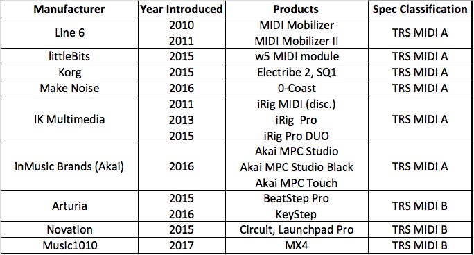
Type B is used by Arturia, Novation, and 1010Music.
I must note that the MIDI “Type A” pin-out is going to be the standard going forward. Unfortunately, the MIDI Association didn’t get ahead of manufacturers when they began using 3.5mm jacks. For reference, the Type A pin-out is:
    DIN      3.5mm
    -----    --------------------
    Pin 4    Ring (Current Source)
    Pin 5    Tip (Current Sink)
    Pin 2    Sleeve (Shield)
Type A is used by Akai Pro, IK Multimedia, Korg, Line 6, littleBits, and Make Noise. I found the chart below to be quite helpful in running down an appropriate adapter cable. (Source: MIDI Association 3.5mm stereo TRS to MIDI 5-pin DIN cables)
Thanks to all of the Christmas prep, I didn’t miss a step while waiting for the 1010Music adapter to arrive. (It’s Advent after all.) I detest making cables and the 1010Music adapter is reasonably priced.
I also got down to work on a MIDI test sketch for the D9U. (Code appears at the end of this post.) The sketch does not use the Arduino MIDI library because it simply sends MIDI note ON and note OFF messages through the MIDI port.
If you’re new to Arduino Leonard — the D9U’s Pro Micro is a Leonardo — you may not know that Leonard has two serial ports: Serial and Serial1. The first port, Serial is dedicated to USB communications. The second port, Serial1, is dedicated to the digital RX and TX pins, similar to Arduino UNO, et al. The naming convention sometimes confuses coders who are new to Leonardo. In our case, when we want to send MIDI, we use the Serial1 port, which must be configured for the MIDI baud rate, 31,250Hz.
The sketch repeatedly sends MIDI note ON and OFF messages such that you should hear a steady series of staccato notes when the MIDI message stream is sent to a tone generator. In my case, I connected the D9U to my trusty Yamaha QY70 sequencer and tone module.
Here’s another little twist. Leonardo is equipped with two additional LEDs: TXLED and RXLED. These LEDs flash when there is transmit and receive activity (respectively) on the USB port. The test sketch does not use the USB port (Serial), so the TXLED and RXLED are ours to play with. The four macros:
    TXLED0 ;      RXLED0 ;
    TXLED1 ;      RXLED1 ;
control the LEDs. If you compile the sketch on a regular Arduino (e.g., UNO), these macros will be flagged as undefined symbols.
Extra credit
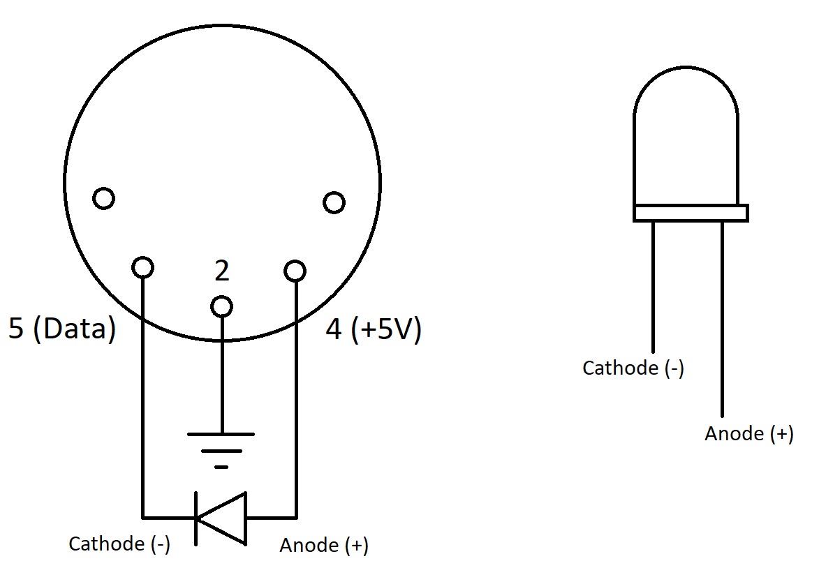
While wading through the Type A vs. Type B nonsense, I did a few simple experiments with the D9U’s MIDI port. For example, you can check the signal levels using a digital multimeter. DIN pin 2 should read as 0 Volts (ground) while DIN pin 4 should be +5 Volts. DIN pin 5 is the data pin which pulls the MIDI current loop to ground. Please remember that MIDI is a current loop where:
- Logic 1 → High → no current flow → Opto-isolator LED off → MIDI receiver sees High, logic ‘1’ (data bits, stop bit or idle)
- Logic 0 → Low → current loop flow rarr; Opto-isolator LED on → MIDI receiver sees Low, logic ‘0’ (data bits, start bit)
Thanks, Wikipedia.
The sender (MIDI OUT) turns an LED on and off in the receiver (MIDI IN). The LED is part of an opto-isolator which provides electrical isolation between the sender and the receiver.

So, if you want to check out MIDI signals at the pins, all you need is an LED and a current limiting resistor (e.g., 330 ohms) in series in the current loop. The LED lights when connected in the direction of positive current flow. Here are my handwritten notes.
David Battino would be proud. David loves to add flashing LED eyes to Japanese movie monster toys and more. One of these days I’ll put all of those Godzillas in our basement toy chest to work. 🙂
Copyright © 2018 Paul J. Drongowski
/*
 * MidiTest.ino: Crumar D9U MIDI and slider test
 */

/*
 * Author:  P.J. Drongowski
 * Address: http://sandsoftwaresound.net/
 * Date:    11 December 2018
 * Version: 1.0
 *
 * This test reads the current slider values. If there is a
 * change, it prints the current slider values to the Arduino
 * serial port. Watch the values change in the IDE's Serial
 * Monitor. The incoming slider values are biased so that
 * values range reliably from 0 to 8. (Leonarkdo's Serial
 * port is dedicated to USB communications.
 *
 * Additionally, send MIDI note ON and note OFF messages to
 * the Serial1 port. On Leonardo, Serial1 communicates via
 * the TX and RX pins.
 */

// Pin definitions
#define LED_RED    15
#define LED_GREEN  16
#define BUTTON     5

// Analog pin map
#define NUMBER_OF_SLIDERS 9
int AnalogPinMap[NUMBER_OF_SLIDERS] = {
  A0, A1, A2, A3, A6, A7, A8, A9, A10
} ;

// Global variables
int colorMode = 0 ;
int ledMode = 0 ;
int noteState = 0 ;
int sliders[NUMBER_OF_SLIDERS] ;

// Bias offset for incoming slider values
#define BIAS 32

void sendNoteOn() {
  Serial1.write(0x90) ;
  Serial1.write(36) ;
  Serial1.write(100) ;
}

void sendNoteOff() {
  Serial1.write(0x90) ;
  Serial1.write(36) ;
  Serial1.write(0) ;
}

void changeColors() {
  if (colorMode) {
    digitalWrite(LED_RED, LOW) ;
    digitalWrite(LED_GREEN, HIGH) ;
  } else {
    digitalWrite(LED_RED, HIGH) ;
    digitalWrite(LED_GREEN, LOW) ;
  }
}

void printSliders() {
  for (int i = 0 ; i < NUMBER_OF_SLIDERS ; i++) {
    Serial.print(sliders[i]) ;
    Serial.print(" ") ;
  }
  Serial.println("") ;
}

void checkSliders() {
  int changeFlag = 0 ;
  int newValue = 0 ;
  for (int i = 0 ; i < NUMBER_OF_SLIDERS ; i++) {
    newValue = (analogRead(AnalogPinMap[i]) + BIAS ) / 128 ;
    if (sliders[i] != newValue) {
      changeFlag = 1 ;
      sliders[i] = newValue ;
    }
  }
  if (changeFlag != 0) {
    // If a change was made, print current slider values
    printSliders() ;
  }
}

void setup() {
  // Set up pins
  pinMode(BUTTON, INPUT_PULLUP) ;
  pinMode(LED_RED, OUTPUT) ;
  pinMode(LED_GREEN, OUTPUT) ;

  // Set up Serial1 for MIDI via TX and RX (31,250 baud)
  Serial1.begin(31250) ;

  colorMode = 0 ;
  noteState = 0 ;

  for (int i = 0 ; i < NUMBER_OF_SLIDERS ; i++) {
    sliders[i] = -1 ;
  }
}

void loop() {
  if (digitalRead(BUTTON) == LOW) {
    colorMode = 0 ;
  } else {
    colorMode = 1 ;
  }

  // Make the TX and RX LEDs flash in sync with the notes.
  // The TX and RX LEDs are Leonardo only. Remove the code
  // below when compiling for Arduino UNO, etc.
  if (ledMode) {
    ledMode = 0 ;
    TXLED1 ;
    RXLED0 ;
  } else {
    ledMode = 1 ;
    TXLED0 ;
    RXLED1 ;
  }

  if (noteState != 0) {
    sendNoteOn() ;
    noteState = 0 ;
  } else {
    sendNoteOff() ;
    noteState = 1 ;
  }

  delay(100) ;
  changeColors() ;
  checkSliders() ;
}