I’ve got a stable MIDI event framework up and running. Time to summarize a few lessons learned.
CircuitPython
The CircuitPython libraries are pretty decent overall. AdaFruit did a good job with on-line documentation and I can usually find a helpful example to copy, paste and modify.
Python itself is a PITA. I don’t know why or how anyone calls it a “beginner’s language”. Three big bug-a-boos jump out:
- Spacing. Zealots say, “Oh, you don’t need brackets; indentation handles everything.” I haven’t seen such idiotic enforcement of spacing rules since 1960s FORTRAN. Give me brackets, give me free-form layout.
- Run-time type checking. Python does not do a lot of compile-time type checking. So, you’ll get a clean compile and then stumble on a type compatibility issue during the first run.
- Type conversion. Type conversion can be very weird. Thanks to run-time type checking, it might take several runs to get conversion right.
I’m going to finish the job in CircuitPython out of a spirit of self-discipline. Please teachers, do not inflict this language on new programmers.
AdaFruit hardware
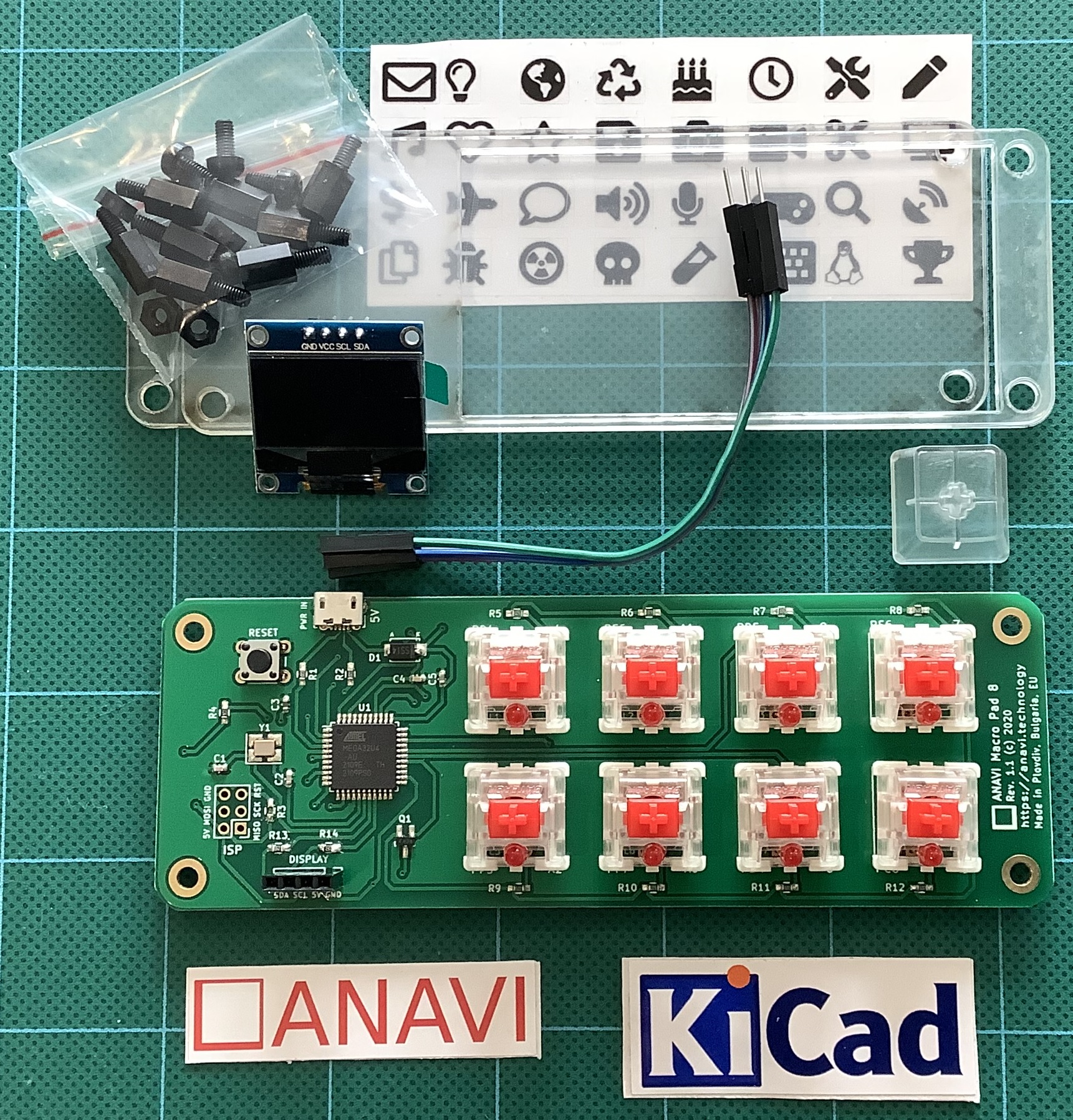
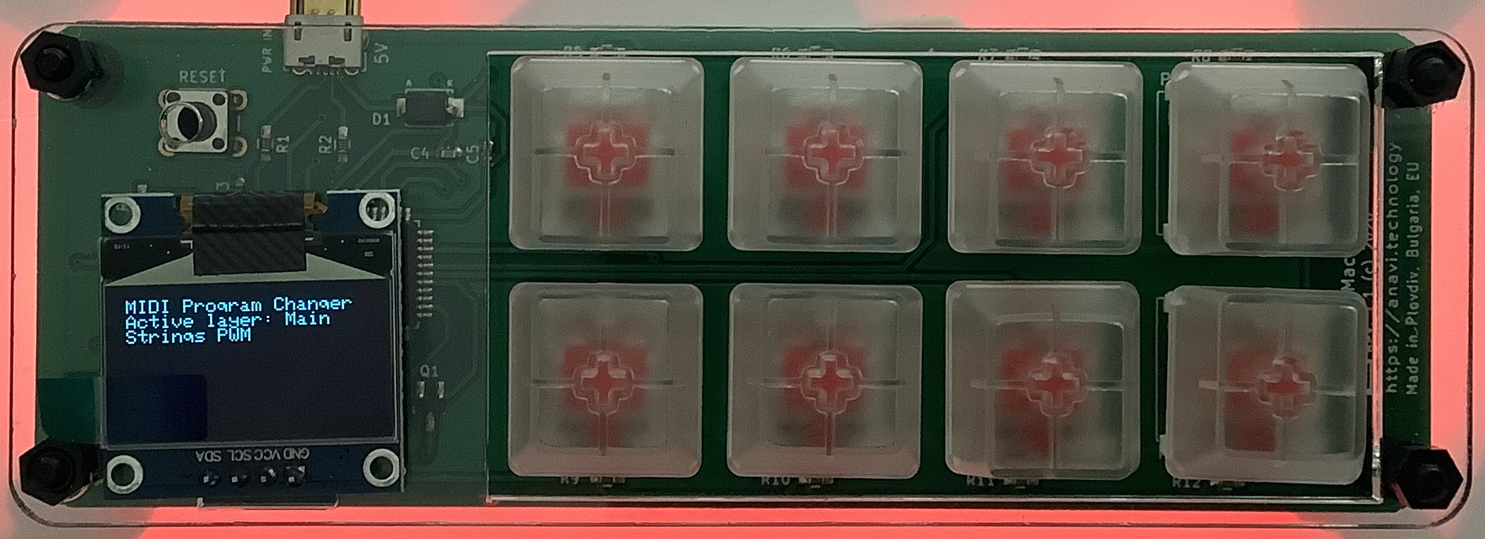
The AdaFruit Feather hardware is solid. No complaints. The AdaFruit Feather M4 Express is a speedy little bugger compared to Arduino UNO! The OLED display is bright and clear. The MIDI ports work. Other than testing, the joystick FeatherWing hasn’t gotten much use yet.
MIDI library
I wanted to love the MIDI library. It offers pre-defined MIDI message types (classes) and necessary send/receive operations. All good.
Unfortunately, I don’t think the MIDI library was tested with a real-world synth. I’m using Yamaha MODX6 for testing. Yamaha uses MIDI running status extensively. Hit and release a key, and MODX sends a NOTE ON status byte followed by two key/velocity pairs:
0x90 0x48 0x73 0x48 0x00
The first pair is NOTE ON and the second pair is effectively NOTE OFF (i.e., velocity is 0x00).
That’s not so bad in itself. However, MODX sends real-time Active Sensing messages (MIDI status byte 0xFE) and Active Sensing may appear in the middle of a MIDI message, running status or not.
Using the MIDI library, notes and controller events were getting dropped everywhere. At first, I thought CircuitPython was too slow to keep up with the incoming MIDI. Nope. When I switched to reading and dispatching bytes from the UART, I could handle everything without straining processor resources.
Bottom line: Bag the MIDI library as it could have bugs with running status.
OLED display and REPL
The OLED display and CircuitPython REPL have been very handy for debugging. The UART implements the MIDI IN/OUT ports leaving USB serial I/O available for debugging. (You need Arduino Leonardo to get separate UART and USB serial I/O.) I like to drop in the occasional “print” statement until I’m sure of the control flow and internal values.
Example: Knowing what the MODX is sending. It is easy to whip up a MIDI monitor sending byte values to either the OLED or the Mu Editor REPL. Knowing that I had to handle Active Sensing and running status together, made the task clear.
The task
Now I realize that the event processing application needs to map note ON/OFF events and to echo all other events (messages) unmodified. My current message processing framework reflects this simplicity. It took a few experiments to get here.
Initial code
If you need a quick start for your own Feather-based MIDI event processor, here is a ZIP file with my initial CircuitPython code. It doesn’t handle complete SysEx messages. The code framework will probably change in the next version.
Copyright © 2025 Paul J. Drongowski