
They just don’t make ’em like they used to. In the case, of the Narbotic Instruments MidiVOX shield for Arduino, I really mean it!
The MidiVox is a bit of a blast from the past as Narbotic no longer manufacture and sell the MidiVOX shield kit. Major bummer. Luckily, I purchased one of these little gems from the MakerShed when the shields were available a few years ago. Narbotic kindly maintain the design information and code on their Web site.
To me, the MidiVox is a most logical combination of a MIDI IN port and a 12-bit digital-to-analog converter (DAC). The MIDI port incorporates a 6N138 optocoupler for electrical isolation and a 5-pin DIN connector. The port is connected through a “PGM/MIDI” switch to Arduino digital pin D0, also known as the serial receive (RX) pin. The PGM position connects the serial pin the usual way in order to download to the Arduino. The MIDI position connects the Arduino serial RX pin to the MIDI IN circuitry. The switch component is robust and is easily accessible when the MidiVOX is on top of the Arduino and/or other shields.
The 12-bit DAC is a Microchip Technology MCP4921. This DAC is used in several other audio shield designs including the Adafruit Wave Shield and the Nootropic Design Audio Hacker Kit. The MCP4921 connects to the Arduino SPI port through digital pins D13 (SCK), D11 (MOSI), and D9 (chip select/slave select). Conventional practice recommends using D10 as slave select (SS), but it isn’t a big deal to use D9 instead as this is mainly a software issue. Slave Select (called “chip select” in the MCP4921) chooses and enables communication with the slave device. This capability is essential when more than one device is connected to the same SPI interface as in the case of the Nootropic Audio Hacker shield.
Although it seems like a no-brainer to connect all SPI devices to the Arduino SPI pins, the Adafruit Wave Shield does not follow this approach. It connects the SD card interface to the SPI pins, but connects its MCP4921 to three ordinary digital pins. The Wave shield software bit-bangs the digital pins to transfer data to its DAC. I’m not a fan of this approach, preferring to use standard libraries instead of possibly buggy, poorly documented bit twiddling code.
The MidiVOX shield implements a 2-stage, passive filter following the DAC output. The MidiVOX sends a mono signal through an on-board trim pot into a 3.5mm audio output jack. Trim pots are usually rated for a relatively small number of operating cycles, so it’s best to set this level once and make volume adjusts at an external mixer, preamp, or whatever.
The MidiVOX shield provides a DATA LED controlled by digital pin D7. The shield also has a RESET button (momentary contact switch) connected to digital pin D6. This button is ACTIVE LOW, meaning that the button pulls D6 to ground when it is pressed. Therefore, the pin mode should be configured as INPUT_PULLUP such that D6 is pulled up internally when the button is not pressed (i.e., the momentary contact switch is open).
Construction was easy. The resistors have five color bands, but don’t let this throw you off. The construction directions give the correct color code and you can (and should!) always check resistor values with a meter before insertion and soldering. I replaced the basic header pins with “stackable headers” (two 8-pin and two 6-pin). Stackable headers provide a way to make easy external connections to the shield stack from a breadboard, etc.
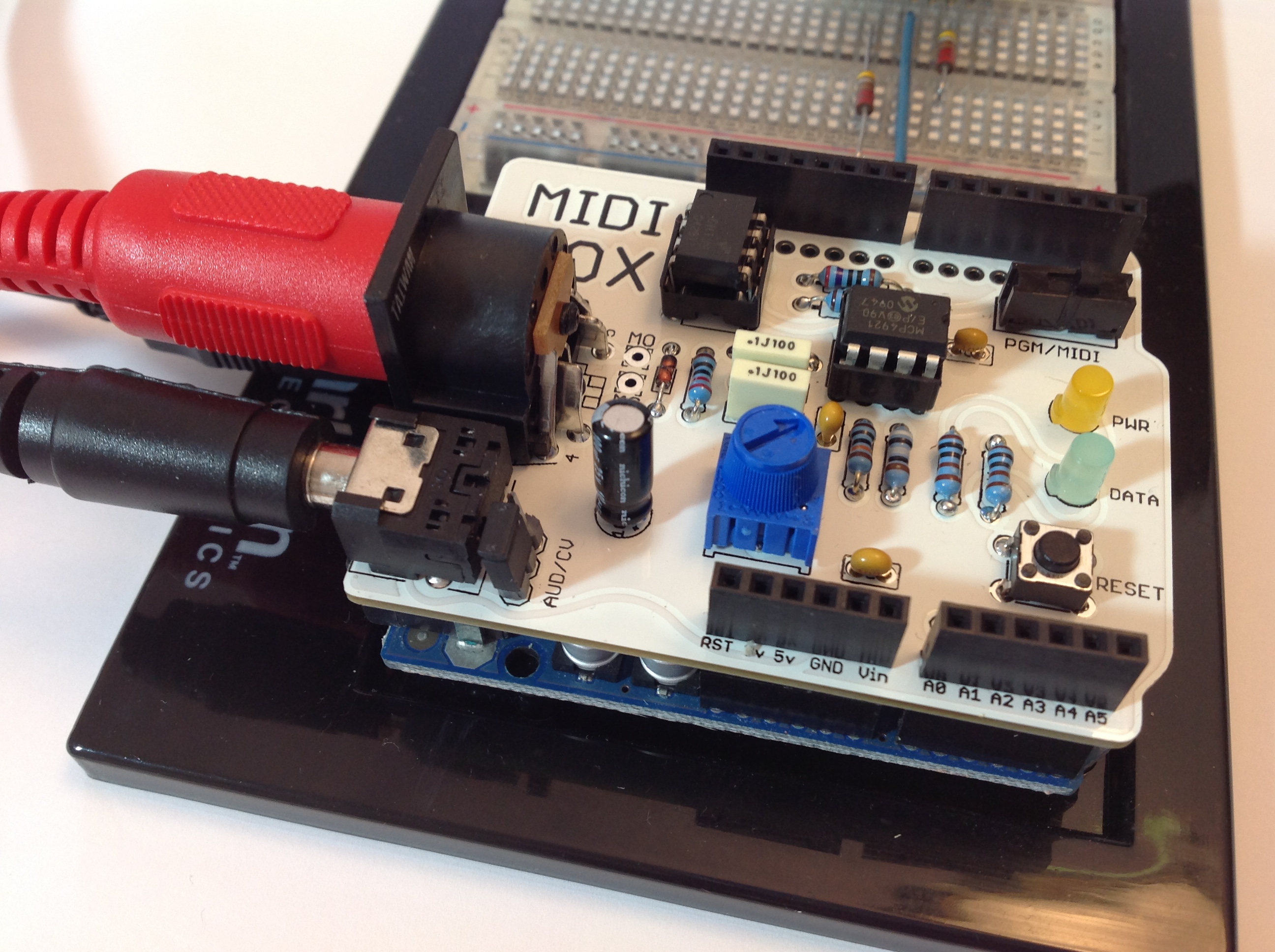
The completed board is shown in the photo below. The MidiVOX is stacked on an Arduino UNO with the USB, audio and MIDI cables, and is ready to go.
I wrote a diagnostic sketch to check out the different parts of the MidiVOX. I wish manufacturers would provide check-out sketches instead of relying on somebody’s possibly flaky application sketch for smoke testing. If something is busted, it’s important to find it early through a directed test that isolates the failure. Fortunately, everything checked out OK the first time!
The MidiVOX diagnostic program is an Arduino sketch to check out parts of a Narbotic Instruments MidiVOX shield. Rename the “loop” functions and rebuild in order to test a particular section of the shield.
Since the MidiVOX is discontinued, we’re all out of luck if we want to get (another) one. However, I strongly recommend studying the MidiVOX design. When I first got started with Arduino and MIDI, I borrowed the MIDI IN circuitry and the low pass filter design. These are simple, solid circuits and are good basic building blocks for other designs and applications.
Where to next? My dream is to build a low-cost 60s combo organ with the era-appropriate look and sound. The organ would look like a Vox Continental with a Z-shaped chrome stand and bright red Tolex covering. It would sound like either a Farfisa or a Vox — nothing too nuanced with all of the drawbars or tabs turned on. I’d like to use a cheap and lightweight MIDI controller as the keyboard. The controller would drive a low-cost (Arduino-based?) sound generator. I’m hacking out a prototype using an Arduino UNO and the MidiVOX shield. More to come…