
I promised a few thoughts about modding the new Yamaha PSS series keyboards. Here goes…
As shown in my PSS-E30 Remie tear-down, a PSS family keyboard consists of four major parts:
- Mini keybed
- Digital logic board (DM)
- Front panel board
- Plastic skin and parts
For comparison, I recommend this excellent PSS-A50 demo and tear-down on YouTube.
Product personality is determined by the plastic skin/parts, software in the embedded serial ROM, and the addition/absence of the USB interface integrated circuit (IC). There may be a few other minor differences, but it would be difficult to pin them down without the service manuals. Speaking of which, if you start a mod project, I strongly recommend reading the PSR-F50 Service Manual because the F50’s guts are very similar to the PSS series.
Unless you really want the F50 or E30 voices and functionality, the A50 is the best choice for a mod. The A50 has the USB interface IC and the necessary firmware supporting MIDI over USB. The A50 has a higher street price than the other models, but USB MIDI is worth it.
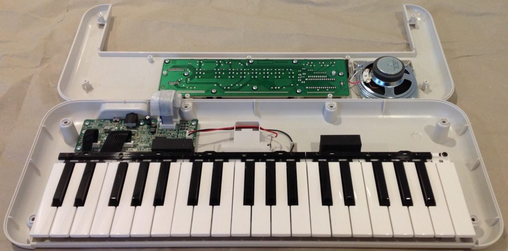
At the 100,000 foot level, there is plenty of empty space inside for a small microcontroller (e.g., Arduino) or sound mangling analog electronics. You could choose to either keep the speaker if you want portable sound or ditch the speaker and go solely with the headphone output to external amplification.
If keep the speaker, you could easily add some sound mangling circuits like a filter or effects. The littelBits filter might be a good start and is certainly small enough to fit in the empty space. Should be easy to tap into battery power as the battery leads are exposed.
If you ditch the speaker, you have a lot more space to work with. I’d be tempted to add the Korg NTS-1 once it’s available. The NTS-1 can process external audio and has digital effects. Previews have given the digital effects high marks. Unfortunately, the NTS-1 is spec’ed 12.9cm by 7.8cm by 3.9cm, which won’t fit directly into a PSS case. A lot depends upon the size of the NTS-1 electronics board. Even if we can’t fit the NTS-1 into a PSS case, the NTS-1 would be a nice complement to the A50.
Without the speaker, one could use the front panel real estate for additional controls. With all of the arpeggios and such, manual control over filtering and effects would be welcome (in addition to the A50’s fixed motion effects).
At the 50,000 foot level, any one of the PSS models could be stripped down for parts. The case and front panel may or may not float your boat, but you could use the shell and front panel for a keyboard project of your own. It would be easy to apply new graphics to the front panel. The front panel buttons are a switch matrix which can be easily mapped out and then scanned by your code. The front panel has a three digit 7 segment display that needs to be multiplexed and driven.
The keybed is quite useful. The keys are affixed to the bottom of the case, so unless you’re reusing the case, too, you probably will need to cut the keybed out of the case, leaving everything as a unit. The keys sit above a printed circuit board (PCB) with the rubberized switch contacts.
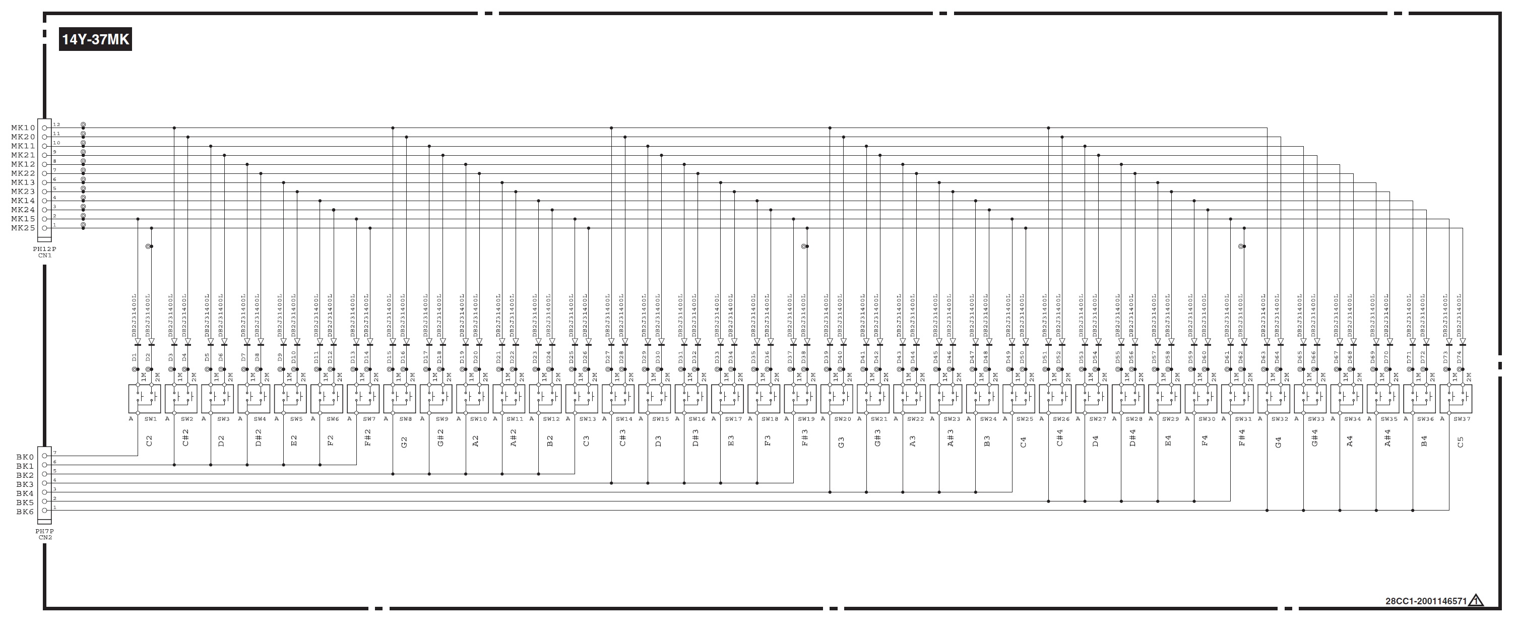
I’ll make a leap of faith here and assume that it’s the same keybed as Reface. The schematic above is taken from the Reface YC Service Manual. The key matrix has seven select lines (BK0 to BK6) and twelve sense lines (MK10 to MK21). Your software needs to drive one of the select lines and immediately read the sense lines. There are two sense lines per switch for the “lower” and “higher” key contacts. Software can determine key velocity by measuring the time between contact closures for an individual key.
The most tasty enchilada is the digital logic (DM) board. The A50 board, in particular, could form the basis of a USB MIDI tone module. One could add 5-pn MIDI by bridging a 5-pin DIN and the USB micro-B port. The DM board is quite small: 13.5cm by 4.5cm. And clearly, the DM board can be battery powered. Even if you re-housed the DM board and front panel board, you still would get a very compact module.
Modding at the 10,000 foot level gets difficult. There are the usual difficulties tracing signals and soldering surface mount (SMT) devices and signal paths. Even if you strip out the SWLL (YMW-830) integrated circuit, I’m not sure what you would do with it!
Nor am I confident that the firmware can be easily by re-engineered. Yamaha have never documented wave chip internals, so you don’t have much guidance. There isn’t much code — firmware and waveforms reside together in the 2MByte serial ROM. I would guess that the firmware is SH architecture. Even so, reverse engineering would be a difficult task. I have my doubts about repurposing the code. At best, one might be able to add or change the waveforms?
Personally, I’m inclined to go the sound mangling route.
A few more thoughts before closing.
The A50 is not a General MIDI module. If you want a (mostly) GM/XG compatible Yamaha tone module, I suggest the Pocket Miku NSX-39. Also, while stumbling around the web, you might want to check out the Yamaha YMF-825. It’s a 4-op FM chip which Yamaha released for makers.
Copyright © 2019 Paul J. Drongowski
Except service manual excerpts which are copyright Yamaha.