
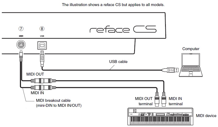
The Yamaha Reface series keyboards have a small DIN-6 connector that carries both MIDI IN and MIDI OUT signals. The keyboards ship with an adapter that converts DIN-6 to two standard 5-pin DIN connectors. Plug in the adapter cable, connect with standard MIDI cables, and you’re good to go.
A few people on the Yamaha Synth site inquired about the Reface MIDI pin-out. Their questions piqued my curiosity leading to a dive into Yamaha service manuals. The results are posted below along with some essential background information about MIDI signaling.
Use this information at your own risk. That goes for anything on my site!
Although I’ve assembled many boards and kits, I make horrible cables. I much prefer to use commercial MIDI adapters and cables. Life is too short to debug and repair shoddy, unreliable cables. Plug and play solutions are the most flexible; you never know when you’ll need a different configuration of female sockets and male plugs. Adapters like the Yamaha Reface adapter are the most flexible, reliable solution although they are product specific.
The Yamaha part number for the Reface MIDI adapter cable (MD6P-DIN) is ZP893500. If you are a USA customer, you can order the cable on-line from Yamaha 24×7. Last I checked, the cable is also available from the on-line retailer Full Compass. I’ve ordered from both Full Compass and Yamaha 24×7 in the past and they both get a thumbs up.
MIDI background information
If you’re going to do anything with MIDI hardware or software, I strongly recommend becoming a member of the MIDI Association. Please take a look at the MIDI circuit reference design:
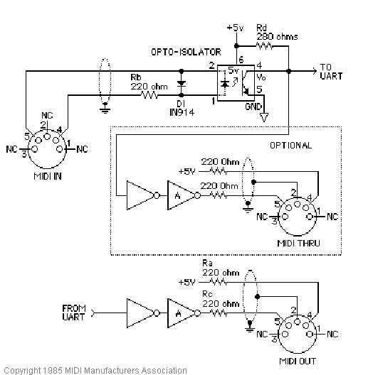
This is the original electrical specification diagram. It’s good enough to understand MIDI operation. The original circuit has been superceded by version 1.1 which includes important additions for 3.3 Volt operation and reduced radio frequency interference (RFI). Register to become a member and download the new reference circuit.
As the MIDI specification notes, “The MIDI circuit is a 5mA current loop; logical 0 is current ON.” The MIDI sender and the MIDI receiver are optically isolated. The sender (MIDI OUT) controls an LED embedded within the receiver’s opto-isolator (MIDI IN).
The DIN connector on the MIDI OUT side has the following pins:
- Pin 1: No connection (NC)
- Pin 2: Ground
- Pin 3: No connection (NC)
- Pin 4: Connected to +5V (3.3V) through a current limiting resistor
- Pin 5: Serial data output (UART TX)
The DIN connector on the MIDI IN side has the following pins:
- Pin 1: No connection (NC)
- Pin 2: No connection (NC)
- Pin 3: No connection (NC)
- Pin 4: LED anode (+)
- Pin 5: LED cathode (-)
Pin 2 may optionally be connected to ground through a capacitor. Please see the current MIDI specification for more info. (Become a member!)
The goal is to turn the opto-isolator LED ON and OFF. The LED polarity (direction of current flow) is important. The MIDI sender turns the electrical current ON and OFF, that is, it turns the LED ON and OFF. This action sends a serial stream of bits from the sender to the receiver.
While writing, it occurred to me — the MIDI Association never formally named these signals. Thus, you get my names like “the thingy connected to the anode of the LED.”
Example: PSR-S910
The following diagram is the MIDI IN and MIDI OUT circuit within the Yamaha PSR-S910 arranger workstation. [Click on the image to enlarge.] I went back to this older product because it uses a transistor pair on the MIDI OUT side, just like the Reface series. That should make it easier to match up the MIDI signals with the Reface DIN-6 pins. Recent products employ a logic gate instead of a transistor pair to switch current through the MIDI loop.
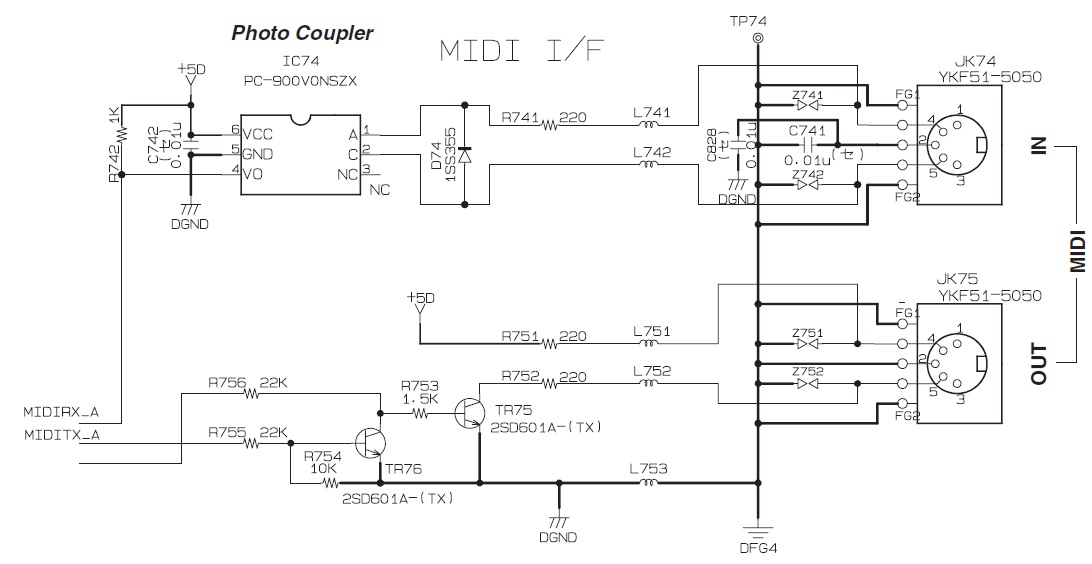
Please note that the S950 MIDI signals are exactly what we expect knowing the MIDI reference design. The “extra stuff” suppresses RFI among other things.
Example: Reface CS
The diagram below depicts the Reface CS MIDI interface circuit (with a few edits for brevity and format). The Reface circuit is similar to the S910 circuit.
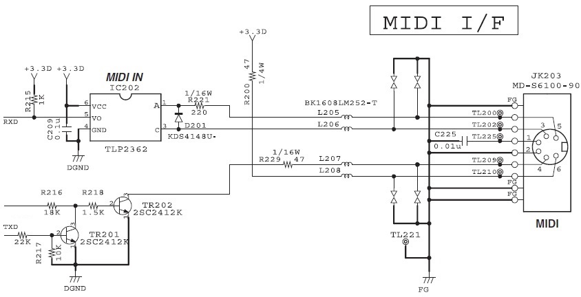
Here are the MIDI signals at the Reface DIN-6 pins:
- Pin 1: MIDI IN, Ground via decoupling capacitor
- Pin 2: MIDI OUT, Ground
- Pin 3: MIDI IN, LED cathode (-)
- Pin 4: MIDI OUT, TX serial data
- Pin 5: MIDI IN, LED anode (+)
- Pin 6: MIDI OUT, pull-up to 3.3V
Please note the DIN-6 pin numbering, position and connector orientation!
Now, let’s match up the Reface DIN-6 pins to regular MIDI DIN-5 pins. The MIDI IN match ups are:
       MIDI IN      MIDI IN
    Reface DIN-6   MIDI DIN-5      Function
    ------------  ------------   -------------
                     Pin 1       No connection
        Pin 1        Pin 2       Ground via decoupling capacitor
                     Pin 3       No connection
        Pin 5        Pin 4       LED anode (+)
        Pin 3        Pin 5       LED cathode (-)
I put the MIDI DIN-5 pin numbers in ascending order. The MIDI OUT match ups are:
      MIDI OUT      MIDI OUT
    Reface DIN-6   MIDI DIN-5      Function
    ------------  ------------   -------------
                     Pin 1       No connection
        Pin 2        Pin 2       Ground
                     Pin 3       No connection
        Pin 6        Pin 4       Pull-up to 3.3V
        Pin 4        Pin 5       TX serial data
At this point, I suggest grabbing your Reface MIDI adapter cable and tracing the DIN-6 to DIN-5 connections with a continuity checker. This is the best way to come to grips with the real-world connections and signal/pin positions.
Copyright © 2017 Paul J. Drongowski
Reface and PSR-S910 diagrams are Copyright © Yamaha Corporation