MIDI TRS pin-out

The MIDI Association has released Recommended Practice #54 covering the use of TRS connectors for standard current loop MIDI. If you’re not a member of the MIDI Association, I strongly recommend becoming a member. Among other benefits, members have access to the Association’s on-line specifications and recommended practices.

Without putting too fine a point on it, the diagram from RP#54 says nearly all. [Click image to enlarge.]

MIDI device designers are facing the same sort of space issues as phone developers. The physical form factors are getting too darned small! In many cases — no pun intended — connector size is a limiting factor. Old school 5-pin DIN connectors are enormous relative to slender product envelopes. The MIDI Association recommends 2.5mm TRS connectors and a maximum adapter cable length of 2 meters.

So, of course, you’re wondering about the MIDI controllers, etc. that you already own. A quick check with a digital meter or continuity checker will determine if your current device is consistent with the recommended practice or not. I checked the adapters with my Akai MPX8 and, yep, the adapters are consistent.

The Korg HNS-4331 MIDI conversion cable is also consistent with the RP #54 convention. Albeit, both the Akai and Korg adapters have 3.5mm TRS plug, not 2.5mm. 2.5mm is a good idea since it would be all too easy to plug 3.5mm headphones or a live LINE output into a MIDI port. Yikes!

The IK Multimedia cable that came with my iRig MIDI is a bit of an oddball. First, the 5-pin DIN connector is male, not female as shown in the diagram above. Further, the pin 4 and 5 connections are swapped relative to the pin wiring shown above. So, if you’re wiring for IK Multimedia, please take care and check things out for yourself using a continuity checker.

Sure wish this recommended practice was available a few years ago…

In case you missed it, here’s the MIDI reference circuit.

Please join and be sure to read the 2014 update to the MIDI electrical specification.

Copyright © 2018 Paul J. Drongowski

Reface MIDI pin-out

The Yamaha Reface series keyboards have a small DIN-6 connector that carries both MIDI IN and MIDI OUT signals. The keyboards ship with an adapter that converts DIN-6 to two standard 5-pin DIN connectors. Plug in the adapter cable, connect with standard MIDI cables, and you’re good to go.

A few people on the Yamaha Synth site inquired about the Reface MIDI pin-out. Their questions piqued my curiosity leading to a dive into Yamaha service manuals. The results are posted below along with some essential background information about MIDI signaling.

Use this information at your own risk. That goes for anything on my site!

Although I’ve assembled many boards and kits, I make horrible cables. I much prefer to use commercial MIDI adapters and cables. Life is too short to debug and repair shoddy, unreliable cables. Plug and play solutions are the most flexible; you never know when you’ll need a different configuration of female sockets and male plugs. Adapters like the Yamaha Reface adapter are the most flexible, reliable solution although they are product specific.

The Yamaha part number for the Reface MIDI adapter cable (MD6P-DIN) is ZP893500. If you are a USA customer, you can order the cable on-line from Yamaha 24×7. Last I checked, the cable is also available from the on-line retailer Full Compass. I’ve ordered from both Full Compass and Yamaha 24×7 in the past and they both get a thumbs up.

MIDI background information

If you’re going to do anything with MIDI hardware or software, I strongly recommend becoming a member of the MIDI Association. Please take a look at the MIDI circuit reference design:

This is the original electrical specification diagram. It’s good enough to understand MIDI operation. The original circuit has been superceded by version 1.1 which includes important additions for 3.3 Volt operation and reduced radio frequency interference (RFI). Register to become a member and download the new reference circuit.

As the MIDI specification notes, “The MIDI circuit is a 5mA current loop; logical 0 is current ON.” The MIDI sender and the MIDI receiver are optically isolated. The sender (MIDI OUT) controls an LED embedded within the receiver’s opto-isolator (MIDI IN).

The DIN connector on the MIDI OUT side has the following pins:

  • Pin 1: No connection (NC)
  • Pin 2: Ground
  • Pin 3: No connection (NC)
  • Pin 4: Connected to +5V (3.3V) through a current limiting resistor
  • Pin 5: Serial data output (UART TX)

The DIN connector on the MIDI IN side has the following pins:

  • Pin 1: No connection (NC)
  • Pin 2: No connection (NC)
  • Pin 3: No connection (NC)
  • Pin 4: LED anode (+)
  • Pin 5: LED cathode (-)

Pin 2 may optionally be connected to ground through a capacitor. Please see the current MIDI specification for more info. (Become a member!)

The goal is to turn the opto-isolator LED ON and OFF. The LED polarity (direction of current flow) is important. The MIDI sender turns the electrical current ON and OFF, that is, it turns the LED ON and OFF. This action sends a serial stream of bits from the sender to the receiver.

While writing, it occurred to me — the MIDI Association never formally named these signals. Thus, you get my names like “the thingy connected to the anode of the LED.”

Example: PSR-S910

The following diagram is the MIDI IN and MIDI OUT circuit within the Yamaha PSR-S910 arranger workstation. [Click on the image to enlarge.] I went back to this older product because it uses a transistor pair on the MIDI OUT side, just like the Reface series. That should make it easier to match up the MIDI signals with the Reface DIN-6 pins. Recent products employ a logic gate instead of a transistor pair to switch current through the MIDI loop.

Please note that the S950 MIDI signals are exactly what we expect knowing the MIDI reference design. The “extra stuff” suppresses RFI among other things.

Example: Reface CS

The diagram below depicts the Reface CS MIDI interface circuit (with a few edits for brevity and format). The Reface circuit is similar to the S910 circuit.

Here are the MIDI signals at the Reface DIN-6 pins:

  • Pin 1: MIDI IN, Ground via decoupling capacitor
  • Pin 2: MIDI OUT, Ground
  • Pin 3: MIDI IN, LED cathode (-)
  • Pin 4: MIDI OUT, TX serial data
  • Pin 5: MIDI IN, LED anode (+)
  • Pin 6: MIDI OUT, pull-up to 3.3V

Please note the DIN-6 pin numbering, position and connector orientation!

Now, let’s match up the Reface DIN-6 pins to regular MIDI DIN-5 pins. The MIDI IN match ups are:

       MIDI IN      MIDI IN
    Reface DIN-6   MIDI DIN-5      Function
    ------------  ------------   -------------
                     Pin 1       No connection
        Pin 1        Pin 2       Ground via decoupling capacitor
                     Pin 3       No connection
        Pin 5        Pin 4       LED anode (+)
        Pin 3        Pin 5       LED cathode (-)

I put the MIDI DIN-5 pin numbers in ascending order. The MIDI OUT match ups are:

      MIDI OUT      MIDI OUT
    Reface DIN-6   MIDI DIN-5      Function
    ------------  ------------   -------------
                     Pin 1       No connection
        Pin 2        Pin 2       Ground
                     Pin 3       No connection
        Pin 6        Pin 4       Pull-up to 3.3V
        Pin 4        Pin 5       TX serial data

At this point, I suggest grabbing your Reface MIDI adapter cable and tracing the DIN-6 to DIN-5 connections with a continuity checker. This is the best way to come to grips with the real-world connections and signal/pin positions.

Copyright © 2017 Paul J. Drongowski
Reface and PSR-S910 diagrams are Copyright © Yamaha Corporation

Connect a MIDI shield to littleBits Arduino

My do-it-yourself MIDI interface for littleBits Arduino probably isn’t for everyone. Constructing the DIY interface requires circuit layout skills and not everyone wants to whip up a board from scratch and a schematic.

Fortunately, there are a couple of alternatives: the Olimex SHIELD-MIDI and the Sparkfun MIDI Shield. I don’t have any direct experience with the Olimex, but I have built and used the Sparkfun MIDI Shield (Sparkfun product number DEV-12898) and the now retired MIDI Breakout Board. The Olimex SHIELD-MIDI is very similar to the retired breakout board. In this post, I show how to hookup the Sparkfun MIDI Breakout Board to the littleBits Arduino. The wiring is the same for the Sparkfun MIDI Shield. That’s the neat thing about the standard Arduino form factor.

I would demonstrate with a Sparkfun MIDI Shield, but all of my MIDI Shields are customized in some way! The Sparkfun MIDI Breakout Board is basically the same as the MIDI Shield except that it doesn’t have the potentiometers and tactile switches. The image below is a picture of the Sparkfun MIDI Breakout board. (Click on the image to get higher resolution.) The two 5-pin DIN connectors are the MIDI IN and MIDI OUT ports. The long pins extending below the breakout board plug into a standard Arduino like an UNO or Leonardo.

sparkfun_midi_breakout

The Sparkfun MIDI breakout board (or shield) arrives as a kit, so you still need to do some assembly. Sparkfun has already installed and soldered the tough stuff like the optoisolator, resistors and so forth. The MIDI Shield is a good beginner’s kit because the components to be installed are large and easy to solder. If you skip installing the potentiometers and tactile switches, the job is even easier!

You might want to add an Arduino Stackable Header Kit (PRT-10007), however. With the header kit, you’ll be able to interconnect using standard jumper wires. Once the headers are installed, no further soldering is necessary. Just plug the jumpers into the headers and play. Mistakes are easier to correct with jumper wires, too.

Here is the top-view of the MIDI breakout board, an Arduino UNO processor board and a Sparkfun MIDI Shield. Click the image for higher resolution. You’ll want to take a closer look at the three boards in order to see the signal name associated with each header pin. (You can really zoom in if you download the image and load it into a paint program.)

midi_bob_uno_shield

The breakout board has a position for a MIDI THRU connector. This position is empty as the headers would block the opening of the 5-pin DIN connector. We don’t need the THRU port, so this isn’t a deal-breaker.

As I mentioned before, the long pins extending below the headers normally plug into a standard Arduino processor board (e.g., UNO or Leonardo). Each header pin effectively mirrors the electrical signals of the underlying Arduino board. So, in order to hookup to the littleBits Arduino, we just need to connect the appropriate Arduino board signals to the corresponding bitSnaps on the littleBits Arduino. That’s why you really want to zoom in and see the signal names. The board labels tell us where to plug in jumper wires.

We need four connections:

  • +5 Volts: Red wire
  • Ground: Black wire
  • RX (digital pin D0): Yellow wire
  • TX (digital pin D1): Blue wire

Our old high school shop teacher would yell at us if we didn’t use the right color wire for power, ground, etc. I will say, different wire colors make it easier to check and debug wiring!

So, how do we make connections to the littleBits Arduino? I used two littleBits proto modules: one proto module for the MIDI input side and one proto module for the MIDI output side. The other end of each jumper terminates in a screw connector on a proto module. Please see the image below. (Click to enlarge.)

sparkfun_midi_littlebits_arduino

RX is connected to RX, TX to TX, +5 Volts to +5 Volts, and Ground to Ground. The MIDI IN goes to the Arduino’s RX pin and the the Arduino’s TX pin goes to MIDI OUT.

You must configure the jumpers on each proto module. The MIDI OUT side is easy; just leave all three jumpers installed. One the MIDI IN side, remove the center jumper on the proto module. This breaks the connection from the proto board input to the proto board output. You must remove this jumper or the input signal will interfere with the incoming MIDI data.

Once all of the connections are made, you’ll need sketches to test the connections. Please see my article about testing an Arduino MIDI interface. The article describes a simple testing process. The article also has links to a simple MIDI sequencer sketch and the source code for a MIDI IN to MIDI OUT sketch. The MIDI sequencer sketch checks the MIDI OUT side. Once you know the MIDI OUT is good, then the MIDI IN to MIDI OUT sketch checks the MIDI IN side. (The sketch echoes MIDI IN to MIDI OUT.)

That’s it! You should now have your 5-pin MIDI equipment talking with the littleBits Arduino. If this project has bolstered your confidence with hardware — and I hope that it has — then please take a look at the DIY 5-pin MIDI interface project.

littleBits Arduino MIDI interface

I thought, “When it comes time to test the 5-pin MIDI interface with the littleBits Arduino, just hook it up. Download the sketches. Take a victory lap.”

Instead, I got an “opportunity” to discover and learn. Not so fast, but not so bad, either.

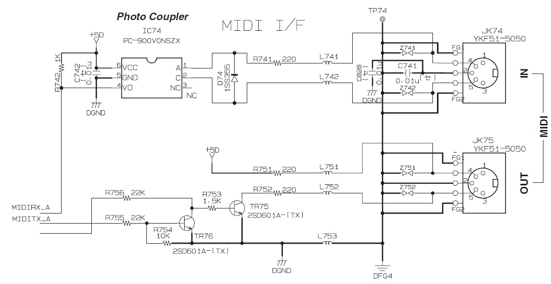
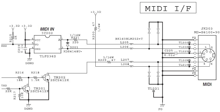
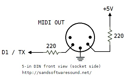
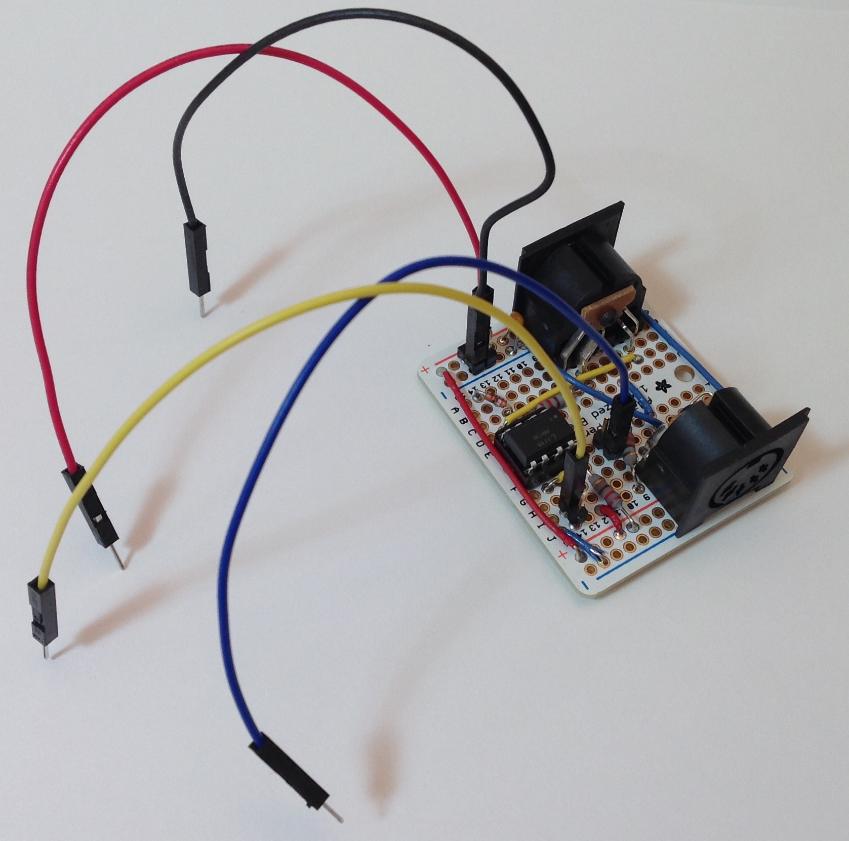
Please recall that a few posts ago I described the design of a 5-pin MIDI interface for Arduino. The MIDI IN part of the interface attaches to the Arduino RX pin (pin D0) and the MIDI OUT part connects to the TX pin (pin D1). I tested the 5-pin MIDI interface with an Arduino UNO board using the simple MIDI sequencer sketch and a sketch to echo MIDI IN to MIDI OUT. My original plan was to connect the 5-pin MIDI interface to the littleBits Arduino via two protoboards, then run the sketches, again, for testing.

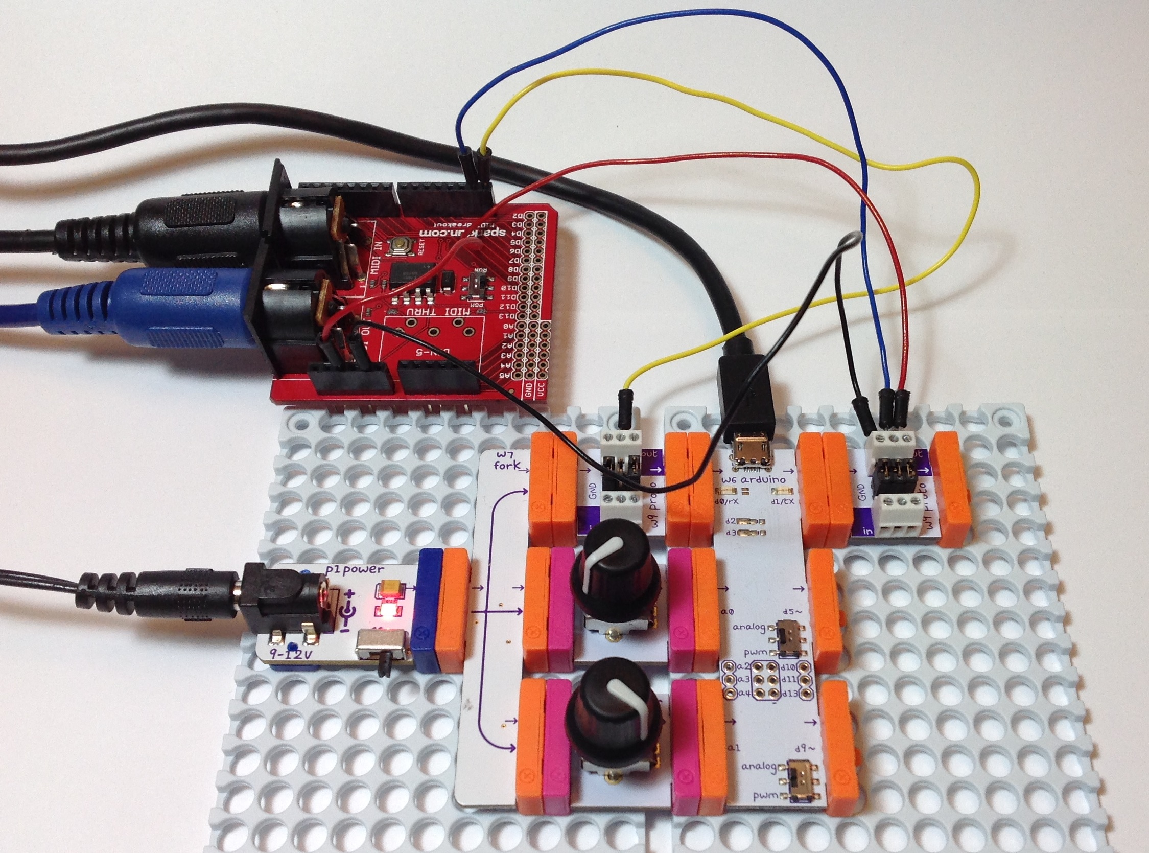
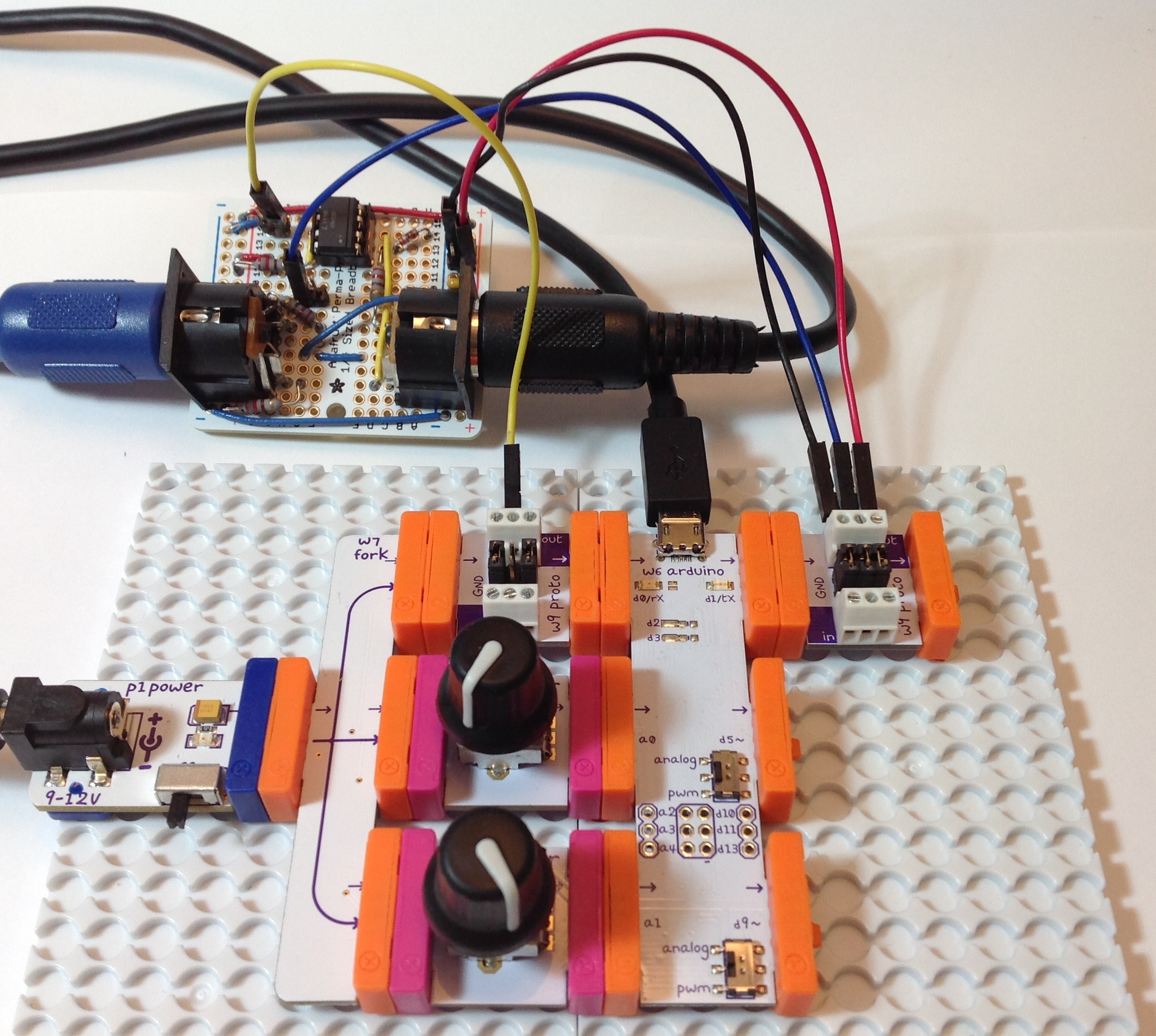
First, the hook up. The image below shows the littleBits hardware. (Click the image for full resolution.) The Arduino is “at the heart” and communicates with a PC through the USB port. The littleBits proto module directly to the left of the USB port brings the logic-level MIDI IN signal to the Arduino RX pin. The proto module directly to the right of the USB port sends the Arduino TX signal to the MIDI OUT circuit. The signals to and from the 5-pin MIDI interface board are:

  • Yellow wire: Logic-level MIDI IN
  • Blue wire: Logic-level MIDI OUT
  • Red wire: +5 Volts (Vcc)
  • Black wire: Ground

MIDI is a serial communication standard operating at a rate of 31,250 bits per second. RX and TX are the Arduino’s digital serial receive and transmit pins, respectively.

littlebits_arduino_midi_interface

So far, so good. There are a few extra details to consider. The positive supply voltage (+5 Volts) and ground are distributed throughout the whole interface board. Only one set of power supply connections are needed to power the interface board. I attached the power supply connections to the proto module handing the MIDI OUT. Next, the proto module jumpers are configured a little bit differently on the MIDI IN and MIDI OUT sides. Having all three jumpers in place, the MIDI OUT proto module passes all signals: Vcc, ground and the data signal arriving from TX. The MIDI IN proto module only passes Vcc and ground. It does not pass the signal from its input bitSnap. The output from the proto module is generated by the signal coming from the 5-pin MIDI interface board (i.e., the yellow wire). This signal is send to the RX pin.

Adhering to my original test plan, I downloaded the simple MIDI sequencer sketch. This sketch tests the MIDI OUT circuit by sending MIDI note on and note off messages. I attached the MIDI OUT connector to a MIDI tone module, flipped the power switch, and no sound. MIDI data was not being sent to the MIDI tone module. After much wailing, gnashing of teeth and browsing, I remembered that the Arduino Leonardo board has two serial ports, not one port like the UNO. One serial interface handles RX/TX and another serial interface handles USB communications.

The littleBits Arduino is a Leonardo board. Was the MIDI data being sent to the USB port? I turned on the Serial Monitor in the IDE. Yep, the Serial Monitor was showing jibberish arriving from the Arduino. I expected jibberish because the bit rate was all wrong, but nonetheless, observations confirmed that MIDI data was going to the wrong port (USB instead of TX).

The Arduino IDE exposes two serial ports for a Leonardo board:

  • Serial” refers to the virtual serial port over USB.
  • Serial1” refers to the serial port through RX/TX.

Originally, I wrote and compiled the MIDI sequencer sketch for an Arduino UNO board. The calls to write() refered to Serial. That’s fine on the UNO because the UNO uses the same serial port for RX/TX and USB communication and everything works. On Leonardo (littleBits), however, the sketch refers to the USB serial port, not RX/TX as I had intended.

I solved the problem with conditional compilation. Here is the new code for the function MidiSend() in the MIDI sequencer sketch:

//
// Send a short, 3-byte MIDI message
//
void MidiSend(byte cmd, byte data1, byte data2)
{
#ifdef LEONARDO
  Serial1.write(cmd | CHANNEL) ;
  Serial1.write(data1) ; 
  Serial1.write(data2) ; 
#else
  Serial.write(cmd | CHANNEL) ;
  Serial.write(data1) ; 
  Serial.write(data2) ; 
#endif
}

The symbol “LEONARDO” determines the code to be compiled into the sketch. If LEONARDO is defined then the sketch sends MIDI bytes to Serial1. If LEONARDO is not defined, then the sketch sends MIDI bytes to Serial. I also needed to fix up the code in setup():

#ifdef LEONARDO
  Serial1.begin(31250) ;
#else
  Serial.begin(31250) ;
#endif

After making these changes and defining LEONARDO at the beginning of the sketch:

#define LEONARDO 1

I compiled and uploaded the sketch. Voila! I heard music from the tone module! MIDI data was now being sent to the appropriate Arduino serial port (TX).

Along the way, I also learned some useful information about the RX and TX LEDs. The RX and TX LEDs flash when data is transfered through the USB port. They do not flash when data is sent through the RX/TX pins. If you want to flash the LEDs yourself, then use the following macros:

    RXLED0;
    RXLED1;
    TXLED0;
    TXLED1;

These macros are a feature of the Leonard board and are not recognized on UNO.

Two separate, independent serial ports has its advantages. First, it isn’t necessary to disconnect the 5-pin MIDI interface board when uploading a sketch. With only one serial port on UNO, TX/RX and USB communication cannot peacefully co-exist. On Leonardo (littleBits), they do peacefully co-exist and you can use the virtual serial port over USB (i.e., Serial Monitor) to trace program execution and print debug messages while using RX/TX for MIDI communication. Finally, if we don’t ever touch Serial1, we should be able to configure D0 and D1 as regular Arduino digital input and output pins (respectively).

By now, you realize that I had to modify the sketch that echoes MIDI IN to MIDI OUT, too. Instead of conditional compilation, this sketches defines a symbolic constant, “SERIALPORT,” which expands to the name of the serial port to be read and written. Full disclosure: I did not test the MIDI library version on littleBits (Leonardo).

//
// Send MIDI IN to MIDI OUT (THRU)
//

// Author:  P.J. Drongowski
// Date:    6 June 2016
// Version: 1.1
//
// Copyright (c) 2016 Paul J. Drongowski
// Permission granted to use, copy and distribute

// Uncomment the following line to use the Arduino 
// MIDI library instead of serial read() and Write().
// #define USE_MIDI_LIBRARY 1
// This has not been tested/debugged on LEONARDO!

// Define the symbol SERIALPORT to select the appropriate
// serial port:
//    Serial    UNO
//    Serial1   LEONARDO/littleBits
#define SERIALPORT Serial1


#ifdef USE_MIDI_LIBRARY

#include <MIDI.h>
MIDI_CREATE_DEFAULT_INSTANCE() ;

void setup() {
  MIDI.begin(MIDI_CHANNEL_OMNI) ;
}

void loop() {
  if (MIDI.read())
  {
    MIDI.send(MIDI.getType(),
              MIDI.getData1(),
              MIDI.getData2(),
              MIDI.getChannel());
  }
}

#else

int midiByte = 0 ;

void setup() {
  // Initialize the serial port for MIDI
  SERIALPORT.begin(31250) ;
}

void loop() {
  if (SERIALPORT.available() > 0) {
    midiByte = SERIALPORT.read() ;
    SERIALPORT.write(midiByte) ;
  }
}
#endif

MIDI sequencer: Testing your MIDI interface

Now that you’ve assembled the MIDI interface for your Arduino, it’s time to try it out. That means you need a few basic sketches to test and debug the interface.

First, a philosophical word or two. Testing is one of the most neglected and least emphasized topics in engineering. Other than careful design, assembly and coding, nothing else is as important to the success of a project as testing. In practice, you should be thinking about testing while you design, code, layout and solder. Without getting too computer science-y, it all comes down to controllability and observability — the ability to apply a stimulus (test input) and the ability to measure and assess a response (expected vs. actual test output).

Take the case of our MIDI interface. There are two major subsystems: the MIDI IN circuit and the MIDI OUT circuit. We must drive the MIDI IN circuit with a keyboard (or some other device) that sends MIDI to the 5-pin MIDI IN connector. The Arduino reads the logic level bit-stream through its RX pin (pin D0). The messages in the bit-stream need to conform to the MIDI message standard. On the MIDI OUT side, the Arduino sends a logic level bit-stream into the MIDI OUT circuit via the TX pin (pin D1). Again, the bit-stream carries standard MIDI messages. We must observe the outgoing MIDI messages, perhaps by playing the MIDI stream into a MIDI-compatible keyboard or tone module.

In addition to controllability and observability, you also need a test plan that identifies the features to be tested and the order in which you intend to test those features. A carefully constructed plan can make your work more efficient and systematic. Again, taking the case of the MIDI interface, I intend to test the MIDI OUT side first because I can easily write a sketch to generate MIDI messages and that sketch does not require a working MIDI IN circuit. Once I know that the MIDI OUT is correct, I can use the MIDI OUT as part of MIDI IN testing. By testing MIDI OUT first, I can work around the limited controlability and observability of our system.

I hope this plan makes sense to you. Here’s a few additional points. We don’t need to test all MIDI standard messages and can restrict testing to simple 3-byte messages like NOTE ON and NOTE OFF. We need to have a reliable, known-good MIDI sender (like a keyboard or other controller) and MIDI receiver (like a tone module). I have two MIDI-compatible devices — a Roland SK-88 Pro Sound Canvas keyboard and a Boss DS-330 Dr. Synth module — that I like to use for testing. Both devices now have emeritus status, meaning that I won’t cry too much if I blow them up! I send the MIDI OUT from the Arduino to both devices and play the audio through self-powered speakers. I play the SK-88 keyboard and send MIDI NOTE ON and NOTE OFF messages to the MIDI IN circuit under test and read those messages on the Arduino.

With these preliminaries out of the way, let’s dive into the details.

MIDI OUT: Simple MIDI Sequencer

In order to test MIDI OUT, we need a sketch that sends MIDI NOTE ON and NOTE OFF messages via the TX pin into the MIDI OUT circuit. With a MIDI tone generator connected to the 5-pin MIDI OUT connector, we just need to listen to the audio from the tone generator to determine if the outgoing notes are correct.

I took the simple Arduino tone sequencer sketch and modified it to send MIDI NOTE ON and NOTE OFF messages. I replaced calls to the Arduino tone() function with code to send MIDI NOTE ON and NOTE OFF as appropriate. (Reusing code this way is known as “copy and modify.”) The new sketch is a simple MIDI sequencer that repeatedly plays back a musical sequence of notes through the MIDI OUT port. The sketch is a useful little program in itself — not just a specialized test.

Here are direct links to the source code for the sketch:

MidiNoteNum.h: Defines symbolic constants for the note names
ToneNote.h: Defines symbolic constands for note/rest durations
MidiSeq.ino: The simple MIDI sequencer Arduino sketch

The sketch does not use the Arduino MIDI library. It sends messages by making calls to the Arduino Serial library. I will use the Arduino MIDI library in future projects, especially when we need to parse complicated incoming messages.

The sketch sends messages on MIDI channel 1. So, be sure to have the destination tone generator configured to receive on channel 1 (or OMNI).

Here’s a possible gotcha that could drive you insane. The Arduino’s serial port is used for both uploading sketches and for MIDI communications. MIDI operates at a rather “unusual” data rate of 31,250 bits per second and most likely does not match the default rate established by the Arduino IDE. Even worse, the MIDI devices used for testing (i.e., keyboard controller) may be sending real time status messages that collide with commands from the IDE. Soooo, you may see messages about “sync” failure when uploading a sketch. If that is the case, then temporarily disconnect the MIDI IN circuit while uploading a sketch. Also, you will not be able to print to the serial port, etc. and see text serial messages in the IDE’s Serial Monitor window. Unfortunately, this limits the use of serial communication for tracing and debugging purposes when MIDI is connected and active.

MIDI IN: Echo MIDI IN to MIDI OUT

Once we know that the MIDI OUT port is working, it’s time to check the MIDI IN port. An easy way to test is to simply echo the incoming MIDI messages to the MIDI OUT port. If we have a MIDI keyboard connected to MIDI IN and a tone generator connected to MIDI OUT, then anything that we play on the keyboard should be heard through the tone generator. If the keyboard and tone generator are part of the same instrument (e.g., a synthesizer workstation, arranger or digital piano), be sure to turn LOCAL off. You want to hear the MIDI messages coming in through the instrument’s MIDI IN port.

Here is the code for the MIDI IN to MIDI OUT sketch.

//
// Send MIDI IN to MIDI OUT (THRU)
//

// Author:  P.J. Drongowski
// Date:    30 May 2016
// Version: 1.0
//
// Copyright (c) 2016 Paul J. Drongowski
// Permission granted to use, copy and distribute

// Uncomment the following line to use the Arduino 
// MIDI library instead of serial read() and Write().
// #define USE_MIDI_LIBRARY 1

#ifdef USE_MIDI_LIBRARY

#include <MIDI.h>
MIDI_CREATE_DEFAULT_INSTANCE() ;

void setup() {
  MIDI.begin(MIDI_CHANNEL_OMNI) ;
}

void loop() {
  if (MIDI.read())
  {
    MIDI.send(MIDI.getType(),
              MIDI.getData1(),
              MIDI.getData2(),
              MIDI.getChannel());
  }
}

#else

int midiByte = 0 ;

void setup() {
  // Initialize the serial port for MIDI
  Serial.begin(32500) ;
}

void loop() {
  if (Serial.available() > 0) {
    midiByte = Serial.read() ;
    Serial.write(midiByte) ;
  }
}
#endif

There are two ways to echo the incoming MIDI message stream. One way is to echo the bytes arriving on the serial input to the serial output. This is the most straightforward method. The other way is to use the Arduino MIDI library to read incoming MIDI messages and send the messages to the MIDI OUT port. The code (above) implements both methods and uses conditional compilation (#ifdef) to select and compile one of the methods. If you want to get your feet wet with the Arduino MIDI library, then define the symbol USE_MIDI_LIBRARY before the #ifdef.

Here are a few links for the Arduino MIDI library to help you get started.

Arduino MIDI Library site
Arduino MIDI Library Documentation
Deprecated site

The current version is 4.2. The Arduino IDE has a nice library management system: Sketch > Include Libraries > Manage Libraries.

5-pin MIDI IN/OUT for Arduino

I hope you enjoyed the last post about a simple tone-based sequencer for littleBits Arduino. My next goal is to make the littleBits Arduino fluent in MIDI. Then we can turn the littleBits Arduino into the heart of MIDI-based tools like real time controllers and synthesizers.

At the time of this writing, littleBits does not offer a 5-pin MIDI input module or a 5-pin MIDI output module. That shouldn’t stop us. With a little know-how and some soldering, it’s easy to whip up 5-pin MIDI IN and MIDI OUT circuits. I will show you how. Even though this discussion is in the context of littleBits Arduino, the circuits below will work with any Arduino. The circuits will even work with Raspberry Pi or Beaglebone for that matter! Once I get a couple littleBits proto modules, I’ll show you how to connect the MIDI interface circuits to the littleBits Arduino.

5-pin MIDI is a mature standard and is one of the most successful, long-running standards in personal computing. Most musicians are familier with MIDI cables and MIDI connections. MIDI cables have familiar 5-pin DIN connectors at either end. Wiring is symmetric. Unlike USB, there isn’t an A side and a B side. Connect a MIDI OUT to a MIDI IN and you’re good to go.

Even though a connector has five pins (and associated wires), only three pins are really involved in MIDI data communication. One of the three pins — “the one in the middle” — carries electrical ground. The other two pins form a current loop from the sender to the receiver and back to the sender. “Current loop” means that we are communicating 0’s and 1’s using the presence or absence of electrical current.

Everyday logic like CMOS or TTL digital circuits use voltage level to represent logical zero and logical one. Low voltage (nominally 0 Volts) represents logical zero and high voltage (nominally 5 Volts in a 5 Volt system) represents logical one. Digital circuits actually switch through a transition zone between 0 and 5 Volts. Logical 0 and 1 are defined by threshold voltages, and now we’re getting too far afield! You get the idea — the representations and electrical mode of operation are different.

Let’s start with the receiver (MIDI IN) because that’s where all of the interesting action takes place. Here is the schematic for a very basic MIDI IN. (Click on images to get full resolution.)

schematic_midi_in

The incoming current flows through a 220 ohm resistor into the optical side of a 6N138 optoisolator. That may sound scary, but Arduino folks already know how to blink an LED on and off. That’s what the current loop does. It blinks an LED in the optoisolator. The LED shines on a photodiode that controls two transistor switches. The transistors switch the output (pin 6 of the optoisolator) between logical 0 and logical 1 (in voltage-ese). Pin 6 is connected to the Arduino serial receive port (pin D0, also known as “RX”). That’s all there is to it!

The optoisolator isolates the sender and receiver electrically. This is a good thing in stage environments and any place rife with grounding problems, connection mistakes, etc. The resistor before the LED limits the current through the loop and into the LED. This resistor plus the 1N4148 diode provide input protection.

Here is the schematic for a basic MIDI OUT circuit.

schematic_midi_out

All the sender needs to do is to drive or remove an electrical current through the loop. When the loop is driven, the LED at the other end of the loop shines. When the current is removed, the LED turns off. The current loop is controlled by the Arduino send port (pin D1, also known as “TX”). The 220 ohm resistors are current limiting resistors that put a limit on the amount of current driven into the loop.

This MIDI OUT circuit gets the job, but is a little basic. Most practical commercial circuits use a driver (such as a CMOS 74HC125 buffer/driver IC) or a transistor switch. The driver provides a little more electrical assurance and protection on the sender’s side. Better to blow up an inexpensive driver IC than your Arduino!

I built both the MIDI IN and MIDI OUT circuits on an Adafruit Perma-Proto quarter-sized breadboard PCB. I like the layout of these boards and they have nice through-holes for soldering. They have the same layout as a quarter-sized solderless breadboard. In this case, you solder connections instead of inserting jumper wires and component leads into solderless breadboard holes. Please, note. If you want to use the circuits above, but are reluctant to solder, then by all means, use a solderless breadboard!

The following image shows the final result looking at the MIDI IN connector. Click the image for full resolution.

board_midi_in

The jumper wires sprouting from the board are not intended to make the board look like a court-jester. They are the connections to be made to the Arduino:

  • Red: +5 Volts
  • Black: Ground
  • Yellow: Connect to D0 / RX
  • Blue: Connect to D1 / TX

My construction style uses 2×1 and 2×2 headers to make external connections. The header pins mate up neatly with either Female/Female or Female/Male jumper wires. I used F/M jumpers in order to plug into the signal headers on a standard Arduino UNO for testing.

The next image shows the final resulting looking at the MIDI OUT connector.

board_midi_out

If you don’t mind soldering, but don’t want to go free-style on a prototyping board, then I recommend the Sparkfun MIDI Shield (DEV-12898). The latest revision of the MIDI Shield has good input protection and output drivers. It also has a RUN/PROG switch that is handy when uploading a sketch to the Arduino. MIDI and PC communications share the same serial port and conflicts must be avoided. (More about this issue in another post.) With the prototyping board, I just pull the yellow jumper wire when I upload a sketch.

The Sparkfun MIDI Shield has two knobs and three switches. This is a bonus if you are working with a standard Arduino. The knobs and switches go unused if you are working with a littleBits Arduino. In either case, the Sparkfun MIDI Shield is a viable alternative to “roll you own.”

Next time, I’ll describe the sketches that I wrote in order to test the MIDI IN and MIDI OUT.

Update: Use this simple MIDI sequencer sketch to test the MIDI OUT portion of the 5-pin interface.