
My ancient Yamaha QY-70 is a handy XG-compatible MIDI module. Quite useful when knocking out a track or two in the dining room. [Table space is tight.]
After 21 years, the back-up battery is nearly kaput and the dreaded “Back-up battery low” message appears whenever I turn on the QY. Fortunately, I’m paranoid as heck about data loss and I’m ready for low battery conditions, a massive cosmic ray burst from outer space, or the apocalypse.
I couldn’t pass up this perfect occasion to take a screwdriver to my beloved partner in musical crime…
First, the service manual. The QY-70 appeared in 1997 followed by its younger and bigger brother, the QY-100, in 2000. The QY-70 service manual is difficult to find on the Web. Fortunately, I had scavenged a somewhat poorly scanned copy two years ago, the original source since forgotten.
               QY-100    QY-70
               ------   ------
    Year         2000     1997
    Polyphony      32       32
    Voices        547      519
    Drum kits      22       20
    Reverb         11       11
    Chorus         11       11
    Variation      43       43
Thank goodness, disassembly is easy — remove the five screws on the back and the QY-70 splits into two halves, top and bottom. Beware if you are doing this yourself as the top and bottom are connected by two relatively flimsy power wires from the battery compartment to the main digital electronics board. (Yamaha always call the main digital board “DM”, by the way.)
Like any good surgeon or forensic anatomist, I took a picture! [Click to enlarge.]
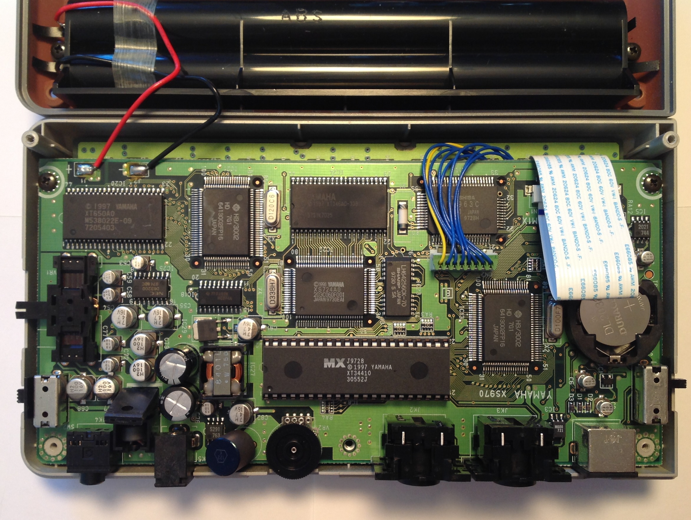
I blew a sigh of relief when I saw the easily accessed button battery, a CR2032 just like the QY-100. [In case you were wondering.] I don’t like to disassemble devices any more than I absolutely have to and didn’t relish pulling the DM board with its connections to the button/LCD board.
So, what is this stuff inside? Here are a few notes from the Yamaha service manual:
    Main CPU         HD6413002FP16      Hitachi H8 3002 10.0 MHz
        Program ROM  341MV030           16Mbits
        SRAM         M5M5256DFP-70LL    256Kbits (32Kx8-bits)
        SRAM         HM628128BLFP-7SL   1Mbits

    Sub CPU          HD6413002FP16      Hitachi H8 3002 12.0 MHz
        Program ROM  MSM538022E         8Mbits
        SRAM         M5M5256DFP-70LL    256Kbits (32K x 8-bits)

    Tone Generator   TC203C060AF-001    SWP00 33.8688 MHz
        Wave ROM     uPD23C32000-12     32Mbits (2M x 16-bits)
        DRAM         LH64256CK-70       Sharp 1Mbits

    DAC              uPD63200GS-E1      NEC 18/16 bit stereo DAC
I’ll bet that you didn’t know that the QY-70 (or QY-100) are multiprocessors?
Renesas was originally established as a joint venture between Hitachi and Mitsubishi Electric. Eventually, NEC Electronics joined the party, too. Thus, the H8 has its origins with Hitachi. Yamaha have been steady users of Hitachi (Renesas) processors for main- and sub-CPUs, having only recently taken a turn toward ARM (Reface, Montage and Genos).
The tone generator (TG) integrated circuit (IC) is smack in the middle of the DM board. It is the component marked “XS724A00”. The tone generator is the first Standard Wave Processor, SWP00M, in a long series of SWPs, culminating with the latest and greatest SWP70. The essential architecture is the same: a controlling host CPU like the H8, wave memory in ROM, and a dedicated RAM for effects processing.
The Sharp LH64256CK-70 is the 128KByte DRAM for effects processing. The component marked “XT346A00”, just above the tone generator, is the wave ROM.
The big dual in-line device (MX) below the tone generator, marked “XT34410”, is program ROM for the main CPU, located just to the right of it. The surface mount component in the upper left corner of the DM board, marked “XT650A0”, is the program ROM for the sub-CPU right next to it.
The NEC DAC is in the same neighborhood. The DAC operates in 18-bit mode and is the same DAC used in the Roland SC-88 Pro Sound Canvas, BTW. The likely sample rate is 44,100Hz as the SWP00 clock frequency is an even multiple of 44,100:
33.8688MHz = 768 * 44,100Hz
Yamaha schematics state memory size in bits, not bytes. Thus, the wave memory is 4 MBytes organized as 2M x 16-bit words. Let’s reflect on that for a moment. The entire XG sound set — drums and all — fits into 4MBytes. Flash-forward to today when people belly ache about 2 gigabytes being just not enough. Yamaha are truly masters at sound design and compression. Let’s hope that its institutional memory and skill live on!
The QY-100 was yet another step ahead in technology, coming just three years after the QY-70. In the QY-100, Yamaha integrated the H8 and tone generator onto a single chip, the SWX00B, first in a long line of SWXs. The QY-100 has a bigger wave memory, 64Mbits organized as 4M x 16-bit words. The memory contains both TG programming and waveforms:
    TG program    1Mbyte
    Waveforms     7MBytes
As noted in the specs, the QY-100 has more voices and drum kits than the QY-70.
Well, I hope you enjoyed the nickel tour. Time to insert a new battery and then to button up the chassis. Have fun!
Copyright © 2018 Paul J. Drongowski