Montage (M)usings

Just in case you don’t have enough to read, here are links to the latest Music Production guides:

It’s raining in The PNW (as usual) and I’ll kick back with these as should you.

Now for a few random thoughts.

Got the power

I owe (Another)Scott for this observation. He found the following error message in the Yamaha Montage M Operation Manual:

CPU Fan Error: The instrument internal cooling fan has stopped.

CPU fan?

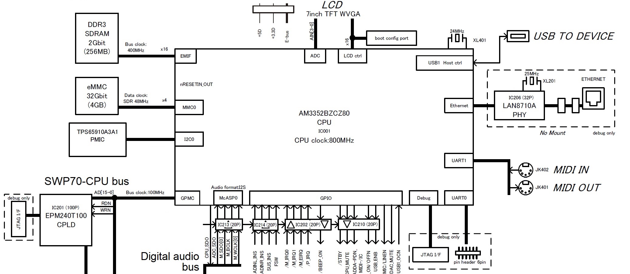
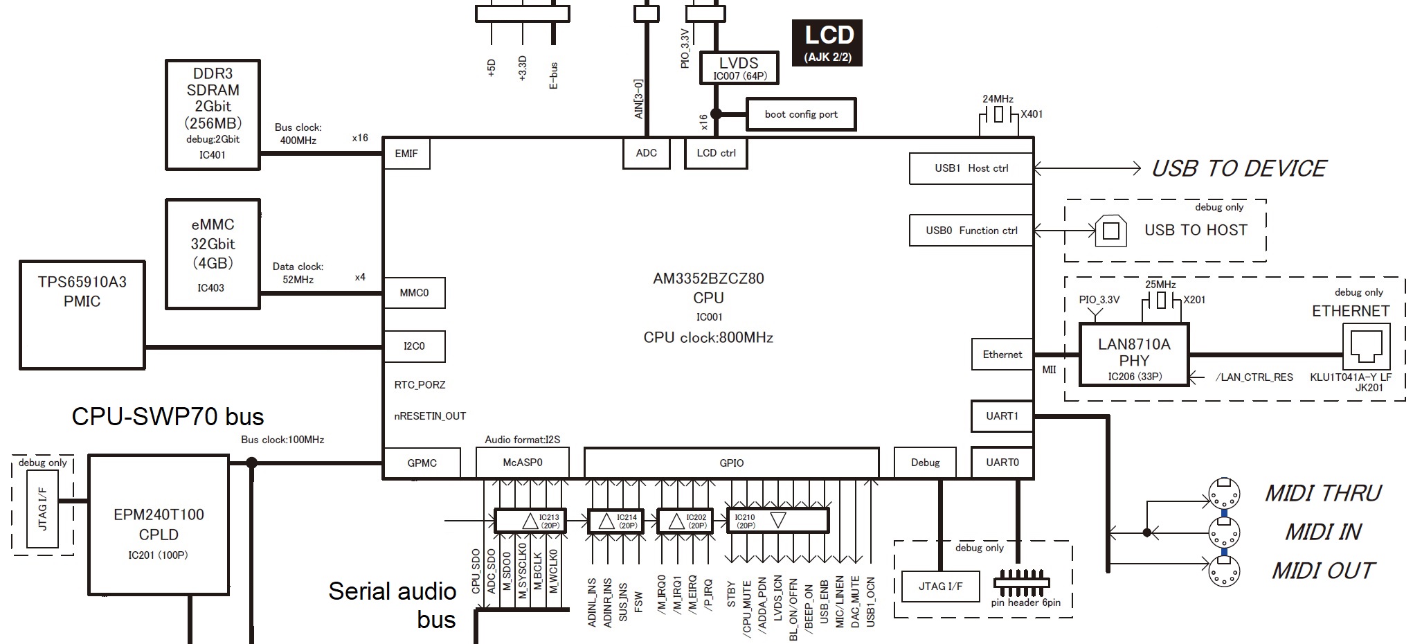
Yes, CPU fan. Demonstrators and punters alike have noted the snappy, responsive Montage M performance. As I thought, Yamaha have upped the host CPU in Montage M. We’ll have to wait for pictures or service manual, but I suspect multi-core (Montage gen 1 is a single core ARM) and/or a higher clock speed.

This means more power in and more power (heat) out.

I wouldn’t expect to find a massive, x86-sized blower and heat sink. Even lowly Raspberry Pi 3 (Broadcom BCM2837 quad-core ARM Cortex-A53 at 1.2GHz) needs a small cooler when running compute-intensive jobs. Raspberry Pi coolers are modestly small and light.

The new Montage M CPU probably includes a more up-to-date, integrated graphics processor, too. It would be interesting to know if the graphics processor (GPU) speeds up the Smart Morph operation. Inquiring minds want to know!

Sub display

I loves me that big old 512×64 LCD “sub display” and the way it is integrated with the rest of the Montage M workflow. The Montage M engineers took this idea from Genos “Live Control” and made it bigger and better in every way.

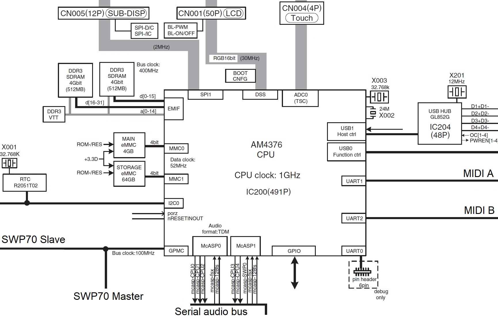
The Genos host CPU (AM4376 ARM operating at 1GHz) handled its sub display over a relatively slow, 2MHz Small Peripheral Interface (SPI) bus.

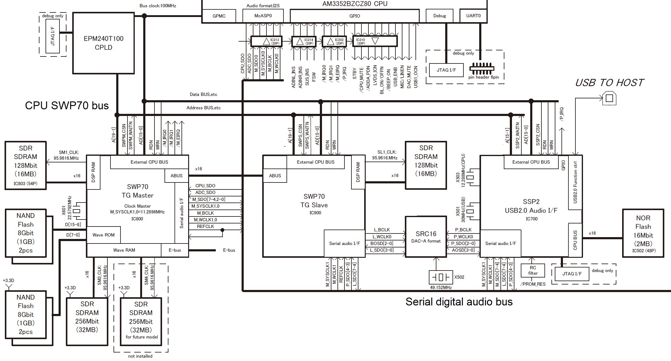
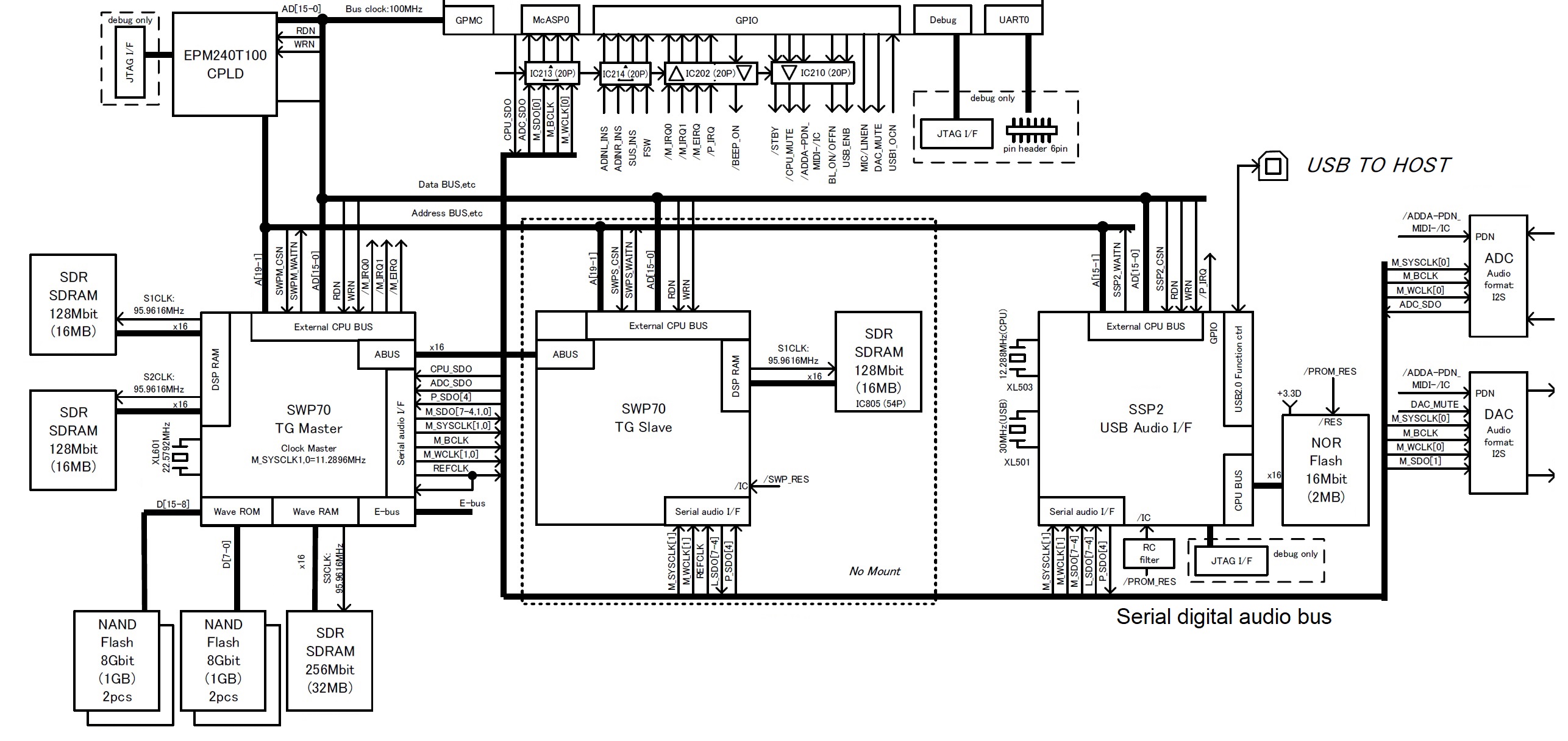
This got me thinking and speculating. The Yamaha SWX09 processor (248MHz internal clock) has a heavy weight DSP, integrated display interface, and low(er) resolution analog-to-digital converters. What if an SWX09 handles the sub display, scans the knobs and sliders, and performs AN-X synthesis? That structure and assignment of duties would make AN-X synthesis incredibly low-latency and responsive to knob and slider control. The SWX09 would need to send controller values over the E-bus to SWP70 and other destinations.

Please file this speculation under “daydreams.”

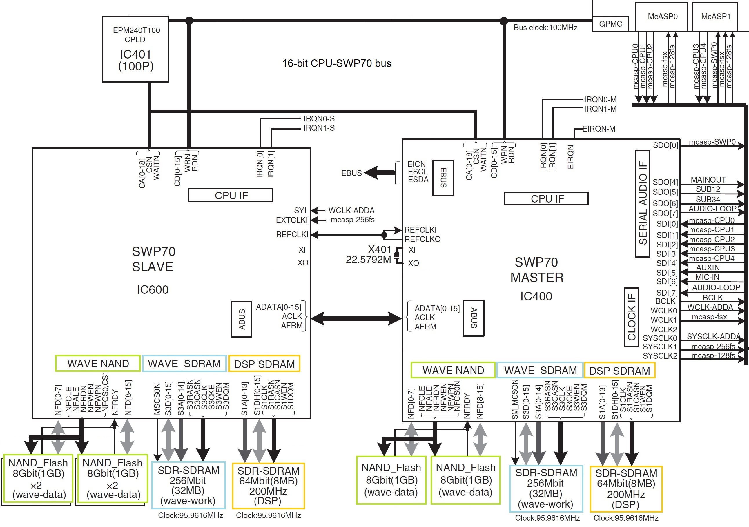
AWM2/FM-X tone generation

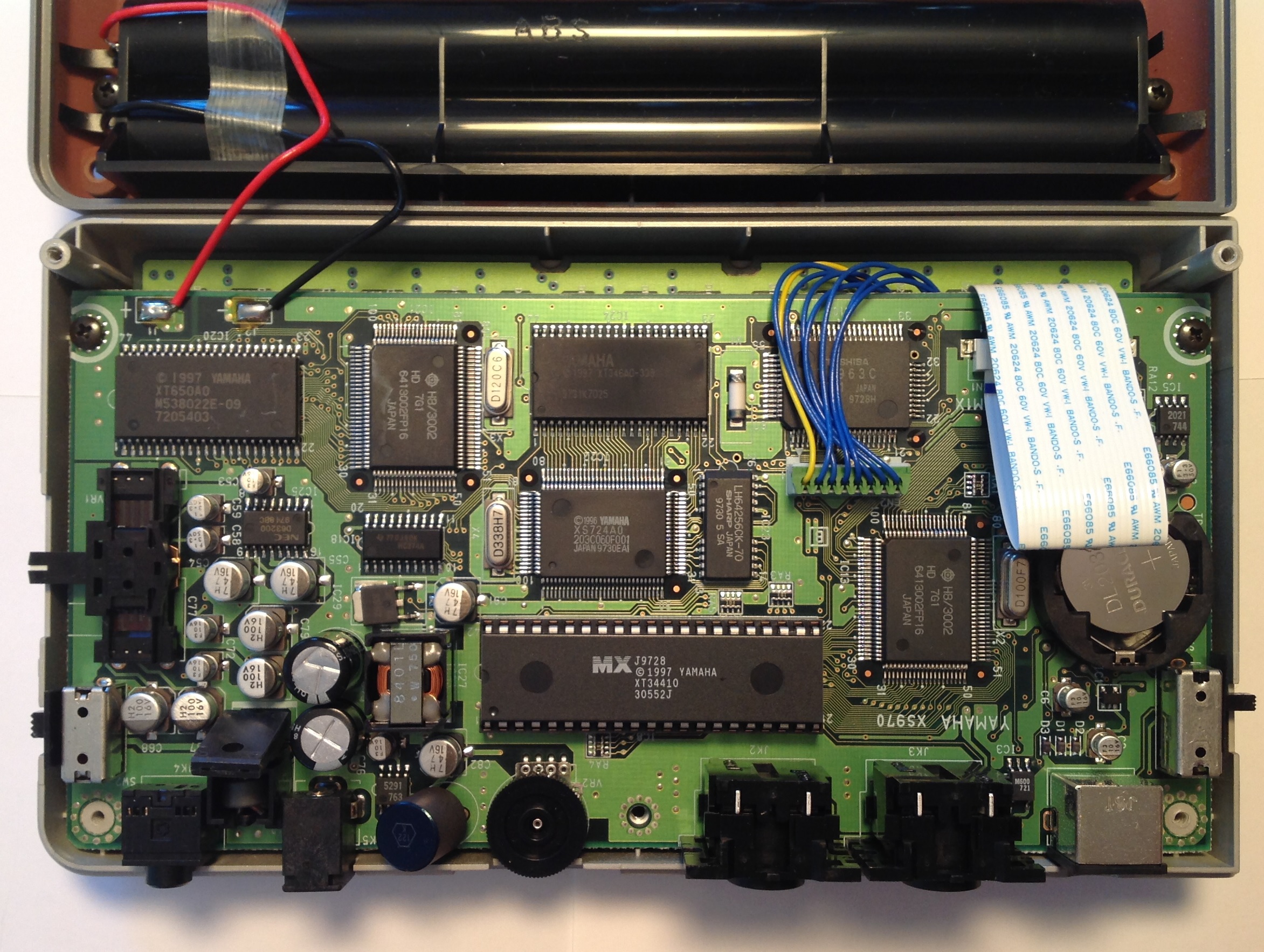
If I had to guess (and I will), Montage M has two SWP70-type “Standard Wave Processors” just like Montage gen 1. AN-X is computed by either an SWX09 or an SSP3. Both SWX09 and SSP3 are SH-2 RISC cores. The SH-2 has been a Yamaha stalwart for nearly two decades, appearing throughout a wide variety of products from audio interfaces, to mixers, to Reface, to digital pianos.

Here’s food for thought. In Montage gen 1, the Master SWP70 handles AWM2. The Master SWP70 has two wave RAM channels: one populated, one empty (“not installed”). Perhaps — perhaps — Yamaha populated the second wave RAM channel and doubled the size of the NAND flash from 4GB to 8GB.

The fly in the ointment is the stated Montage M AWM2 polyphony spec: 128 factory preset elements plus 128 user waveform elements. If both operate from the same NAND flash, then there should not be this artificial split (factory vs. user). Perhaps Yamaha added user NAND flash and wave RAM to the Slave SWP70? Or maybe this is all wet and there is a third SWP70? (See Genos internals.)

128 elements per part

As I mentioned yesterday, allowing up to 128 elements per Performance part is a big win for piano and organ voice programming. In Montage gen 1, sound designers often needed to split voice elements into several Parts, 8 elements per Part (max).

This improvement opens a can of worms with respect to real-time element assignment and activation. The E-bus carries note on/off directly from the keybed scanner to the Master SWP70. How much does the host CPU intervene? Does the SWP70 handle element assignment and activation by itself? If the SWP70 does this by itself, then Yamaha probably needed to revise the SWP70 IC, i.e., a new silicon spin and a new part number (“SWP71”).

BTW, just for kicks, someone should try programming a Performance Part with 128 elements. Hit a note, then hit a second note. What happens?

Fun with fuses

Some folk still conceptualize SWP70 as “a big ole programmable CPU”. I prefer to conceptualize the SWP70 as a collection of AWM2 pipelines, FM-X pipelines, 32 or so very simple DSP effect processors, and a very flexible digital audio mixing system. (Of course, there’s other stuff, too.) The AWM2 pipelines and FM-X pipelines are circuits dedicated to AWM2 and FM-X synthesis, respectively and specifically.

Each group of pipelines reside on their own power and clock grids. Circuit fabrication is not a perfect process. The AWM2 pipes or the FM-X pipes could suffer a fabrication flaw. During QA, Yamaha could sort parts into four categories: both AMW2 and FM-X good, AWM2 good and FM-X bad, AWM2 bad and FM-X good, both AWM2 and FM-X bad. Both sides bad is a reject.

In the cases of one side good, the bad side can be fused off. Yep, there may be fuses to cut bad pipes from the power and clock grids. Parts can be assigned to either AWM2-only duty or FM-X-only duty when a PCB is manufactured.

This is standard industry practice. The processor you are using right now probably has bad circuits fused off!

E.S.P. all over again

Dedicated pipelines are why Yamaha tone generators and polyphony are so predictable and stable. There isn’t any nonsense about effects, this or that cutting into polyphony because everything shares the same processor.

That’s why I don’t expect the Expanded Softsynth Plugin (E.S.P) to provide stellar polyphony. The initial release (“early 2024”) will support sound design. That’s a modest goal for PC-/MAC-synthesis. I wouldn’t expect too much — “all the Montage M sound while being limited to basic editing.” The full version is planned for Summer 2024.

As to development, pricing and distribution, I’m sure Steinberg will have a hand in. Steinberg completed a rent-to-own partnership deal with Splice in April 2023. Yes, Steinberg and Yamaha have caught the subscription model disease. If it’s rent-to-own, the price isn’t going to be cheap. You didn’t expect to get a Montage M for a few bucks, did you? You want to play, you gonna pay.

Copyright © 2023 Paul J. Drongowski

“M” for multi-core? Multi-touch?

One phrase from the Sayonara Montage announcement sticks in my mind: “As much as we would have liked to, we cannot develop the current MONTAGE any further.”

So, how might the current Montage platform be improved?

SWP70 Standard Wave Processor

The current Montage platform has two SWP70 Standard Wave Processors arranged in a so-called — and somewhat offensively named — master/slave configuration. This tandem has been the mainstay of top-end Yamaha synth and arranger keyboards since the early days of Advanced Wave Memory (AWM). The pair are interconnected by a dedicated, addressable 16-bit data bus (ABUS).

The SWP70 is highly tailored for AWM2 and FM-X synthesis. The tone generation channels are dedicated hardware feeding an internal mixing/effects complex. Digital audio is conveyed on- and off-chip via I2S format serial audio streams. The SWP70 can support up to eight input and eight output I2S streams.

I doubt if this microarchitecture will change much. It seems to be entrenched in the Yamaha engineering DNA. There are two possibilities for improvement.

First, the current Master SWP70 uses only one of its two available WAVE SDRAM memory channels. The WAVE SDRAM is where the SWP70 caches samples fetched from ONFI 4.0 NAND flash waveform memory. The Master SWP70 handles AWM2 synthesis alone. (The second SWP70 handles FM-X synthesis and does not have any wave-related memory.) The unused WAVE SRAM channel is marked “Not Installed” and “For Future Model”. Most likely, the second channel would be used to increase the polyphony spec.

Next, Yamaha could re-spin the SWP70, perhaps producing an SWP71 variant. There is precedent for a re-spin. The Motif ES is based on the SWP50 and its successor, the Motif XS, is based on the SWP51. What Yamaha adds to silicon is anybody’s guess. 😉

ARM host processor

The current Montage host processor runs Linux and has many duties — none of which perform synthesis. The host processor is a Texas Instruments AM3352BZCZ80 processor operating at 800MHz.

The AM3352 Texas Instruments Sitara processor has a spec which is nearly quaint by today’s standards:

  • ARM Cortex-A8 32-bit RISC processor
    • Single core
    • NEON SIMD coprocessor
    • 13-stage superscalar pipeline
  • PowerVR SGX Graphics Accelerator

The modest 800MHz clock lets Yamaha hit the desired power/heat operating point, thereby avoiding active cooling.

The key limitation that catches my eye is “single core”. This means that only one computational thread can run at any given time. Yamaha engineers must positively envy Korg’s use of Raspberry Pi 3 (Broadcom BCM2837):

  • Quad-core ARM Cortex-A53 (ARM V8 ISA)
  • 2 wide issue, in-order pipelines
  • 1.2GHz clock

With RPi3, one gives up superscalar for simpler in-order pipelines, but you do get to run four threads simultaneously.

I’m sure Yamaha engineers have studied newer, available embedded ARM processors for Montage M. Does the “M” stand for multi-core?

Guesses, anyone?

If Montage M goes multi-core, this opens the possibility of software instruments (and effects) running on one or more of the host processor cores. Current Yamaha synths allow expansion through sample libraries only, while competitors support the addition of new engines. Kind of ironic considering that its captive Steinberg developed VST plug-ins in 1996.

Even the lowly Korg NTS-1 supports the development and addition of new oscillator and effect models through the logue SDK (API) and librarian.

So, readers of Yamaha Musicians Forum, does the prospect of software plug-ins get Saul’s pulse racing, again? 🙂

The new choice for host processor and its embedded display controller may also give Montage M a new multi-touch display. Could “M” also stand for “multi-touch”. Using the Montage touch screen as an X-Y pad always seemed like a no-brainer… Then there are new possibilities for multi-touch articulation.

It’s worth noting that the new Montage M platform may leave MODX+ in the dust. I don’t expect much functional trickle-down from Montage M to MODX+. The MODX+ platform is riding the profit-pumping, low-cost technology curve and won’t be able to keep up with its jacked brother.

Copyright © 2023 Paul J. Drongowski

Montage: Thank you for playing!

Splashed all over the Interwebs — Yamaha Montage is discontinued after a seven year run.

A tribute

I quite liked Montage from the moment I played it. I opted not to buy it because I need a light-weight gigging instrument and the 61 was simply too much to schlep and set up every week (and/or rehearsal). Thus, I was positively elated when Yamaha announced the MODX as the younger sibling which had all of the Montage sounds I was craving.

As a MODX player, I had the benefit of Yamaha’s new “platform” approach to product development and lifetime management. Instead of forcing customers to buy a new instrument every few years in order to get new features, Yamaha provided periodic updates to Montage. Because Montage and MODX share large amounts of code and content, I got the new stuff as it trickled over to MODX.

I also got the benefit of all the Montage usage tips, explanations and other content posted by Phil Clendennin and Blake Angelos. Thank you, fellows!

The parsing

And, now, everyone is parsing Blake’s announcement. 🙂

“As much as we would have liked to, we cannot develop the current MONTAGE any further.”

Yep, the current hardware platform has run its course. (Even more about the internal design here.)

There is huge expressed demand for a virtual analog engine. The AN-X trademark drove the feeding frenzy throwing chum in the water. For quite some time, I’ve maintained the argument that SWP70 alone is not enough to implement VA synthesis with multiple channels (polyphony). Yamaha tried grafting AN/VL into an AWM synth — the wonderful EX5 — and know the limitations of that approach. Plus, would a punter really be happy controlling VA through the MONTAGE front panel?

“And one more thing… the next generation MONTAGE synthesizer is coming in October.”

October is the important fact, here. If you’ve been reading my recent posts, you know I’m looking for an 88 at home in the studio. If the new ax has wonderful pianos and a decent 88 action, count me in.

Will the new synth bear the mark “MONTAGE”? After a lifetime of choosing variable names, I don’t really care what it’s called. 🙂 How does it play? How does it sound? What’s inside?

Wither MODX+? I think we will see, again, a major split between the MODX product line and the future MONTAGE line. Yamaha is going to monetize those new features (AN-X) and I expect MODX+ to be left behind. That’s marketing for ya.

A gift

“As a thank you we are providing a final set of content free of charge for all MONTAGE owners.” The pack includes three of the character pianos that were released for the YC/CP product lines: Yamaha U1 upright piano, Yamaha C3 grand piano and Felt Yamaha U1 upright piano. I love that felt piano!

I expect to see all of these pianos on the other side along with CFX and Bösendorfer Imperial. Pretty please, Yamaha, with all that extra DSP, may we have VRM, too?

The waiting

So, there you go.

As to the Interwebs, it will be groundhog day all over again as people churn the same bloomin’ rumors, half-truths and nonsense.

As to me, I was getting set to spring for an 88 digital piano. Maybe this is the kick I need to be patient? Yamaha have been rolling out new product like Christmas morn. October isn’t that far away, is it, Santa?

Copyright © Paul J. Drongowski

Yamaha MODX+ madness

Thanks to a few pages posted from the Yamaha MODX+ user manual, the new MODX+ is a bit of a nothing-burger — a product spiff. The MODX+ got a few bumps over MODX (Mark 1): more expansion memory (1.75GB), FM-X polyphony on-par with Montage (128), and a way to add rhythm patterns:

Also, the MODX+ has a new feature for instantly adding rhythm patterns so that the players can take their music creation forward with dynamic rhythm parts. With this feature, creating rhythmic changes in the “Motion Controls” is easier than ever! [Yamaha]

Just enough to keep MODX+ competitive in its price bracket. The bump in FM-X polyphony indicates the likely addition of a second SWP70 tone generator IC.

I suspect Yamaha will use new downloadable libraries to drive a few pack-rat punters to upgrade to MODX+. Recently, IdeaScale participants had a chance to preview a new CP-80 voice (and waveforms). Yamaha were soliciting opinions as to which voices/waveforms had the most sonic appeal. A flood of must-have content might create demand among current MODX (Mark 1) players, making that 1.75GB a necessity.

The forums are filled with speculation about AN-Xâ„¢. Again, a lot of wishful thinking about AN-X coming to Montage and/or MODX+. Only Yamaha know for sure.

As yet, however, no one has solved the mystery of the other registered trademarks: CK61â„¢ and CK88â„¢.

Yamaha have moved on from the SSP2 signal processing chip to the SSP3. The SSP3 first appeared in the Yamaha AXR4U and Steinberg UR44C audio interfaces. Yamaha move ahead like a shark and the SSP2 is deprecated for new designs. In fact, the MODX+ refresh likely includes the SSP3 as SSP2 production inventories must be low or exhausted.

That turns my attention to the Reface DX and Reface CS. The Reface DX and CS are sisters, sharing the same internal design modulo screen interface and front panel gizmos. Both are based on SSP2 and, thus, both may be in need of a refresh — or replacement. The SSP2 signal processor provides the FM and VA synthesis horsepower.

Simply put, will CK61 and CK88 replace the Reface DX and CS? Will the CK61 and CK88 be the AN-X machine? How will Yamaha monetize AN-X? When it comes to business, Yamaha are not fools. Never sell one model when two will do as well! Ka-ching. 🙂

On a personal note, I started this site to inform players about music technology and what’s inside the tin. It’s gratifying to read the forums and see how much this site has influenced discussion, especially discussion about Yamaha products. Thank you for reading and please keep coming back! — pj

A few handy links:

Copyright © 2022 Paul J. Drongowski

You spin me right round

Spot product shortages have sparked speculation about discontinued products, new products, etc. Given the human propensity to look for and find patterns, it’s no wonder that conspiracy theories take hold!

The on-line inventory picture is mixed. Some retailers show Yamaha Montage/MODX, for example, in stock, some show them out of stock pending September availability and, in one case, discontinued.

Random “discontinued” tags seem to come and go. A month ago, the Yamaha Canada site marked the MX as discontinued. Now the marker is gone. Better indicators are blow-out pricing to move stock or a Yamaha spiff incentive to move old stock. So far, I haven’t seen any clearance pricing or promotions.

Yamaha’s mid- to upper-end keyboard products have a vulnerable supply dependency on Asahi Kasei Microdevices (AKM) DACs and ADCs. The AKM factory fire was worse than originally thought and production is still not back on-line. Renesas has offered to manufacture AKM devices. The Yamaha UK site has the disclaimer, “Due to the difficulty in procuring semiconductors and procuring parts worldwide, some of our product area deliveries may be delayed. Thank you for your understanding.”

AKM aren’t very public about their recovery and certainly haven’t released a public roadmap. A recent press release for VELVET SOUND DACs and ADCs mentions sampling (no pun intended) in January 2022 with “mass production scheduled for the third quarter of 2022.” Given that Toyota is a top AKM customer, who wins, Toyota or Yamaha? 😉

The AKM shortage inspires other conspiracy theories, too. Theory #1: Yamaha are using non-AKM DACs and ADCs in Montage — the analog/jack (AJK) board was redesigned or manufactured with inferior non-AKM devices. Theory #2: MODX is suspended in order to give preference to and ship the wider-margin Montage. Someone went so far as to ask about replacement DACs in Montage and got the usual non-response from Yamaha. (What did they expect?)

Some of the Yamaha boards use Yamaha proprietary ICs, e.g., SWL, SWX, or SSP2 processors, creating a different supply dependency. When production inventory is exhausted, Yamaha need to re-spin end product to use a newer part. The July 2016 MX refresh is one interesting example. I believe that was the case with the MX refresh.

I haven’t seen a new version of the heavy weight SWP70 tone generator. However, Yamaha have updated both the SWX and SSP lines:

  • The SWX08 is replaced by the SWX09.
  • The SSP3 — now appearing in Steinberg and Yamaha pro audio products — will likely replace the SSP2.

The SWX update would affect mid-range keyboards, notably the Yamaha Reface CP and YC. The SSP update would affect Montage, MODX, and Reface CS and DX.

Are new product spins in the works? Something is coming (eventually) given the CK61™/CK88™ and AN-X™ trademarks. Once again, only Yamaha really knows. 🙂

Copyright © 2022 Paul J. Drongowski

Yamaha YC series: Tonewheels

overall Speculation about future Yamaha product reminded me of some unfinished business — analyzing the design of the Yamaha YC stage organ series.

Design of the YC series put some of Yamaha’s best minds to work including Dr. Toshifumi Kunimoto. “Dr. K” and his team are well-known for Virtual Circuit Modeling (VCM) and physical modeling (VL). Before reading ahead, it’s worth reviewing my post summarizing YC61 Developers’ comments. The article has link to a (subtitled) interview with Dr. K, Takashi Mori and Akinobu Shibuya. One big take-away is how the developers took a system-wide approach to emulation the Hammond sound.

The YC61 Owner’s Manual cites six specific innovations:

  • Natural, organic harmonies when playing chords — thanks to a matrix circuit that connects the keyboard, tone wheels, and drawbars.
  • Percussion sound with presence — based on vacuum tube circuit analysis.
  • Key clicks and leakage sounds — based on electrical circuit analysis.
  • Natural sound distortion — simulating vintage vacuum tube pre-amplifiers.
  • Vibrato/Chorus effect — from scanner-based vibrato circuitry.
  • Changes in frequency characteristics and drive amount that responds dynamically to operation of the expression pedal.

These innovations are all in the realm of VCM and are needed to re-create the overall Hammond sound.

I assumed that Yamaha modeled the tonewheels, too. Now, I’m not so sure. I think the tonewheel waveforms are sampled and a modified form of AWM2 synthesis generates the basic, uneffected tonewheel signal (in digital form, of course). Here is my justification.

The interview and YC-series documentation

Yamaha are always honest about what they say even if they don’t say everything. Neither the developers’ interview or Yamaha documentation mention modeled tonewheels.

The YC specifications provide an important clue. Yamaha specify YC polyphony as:

VCM Organ + AWM2: 128 (Total of VCM Organ and AWM2), FM: 128

YC series keyboards have a single SWP70 tone generator (TG) integrated circuit (IC). Like the MODX design, the YC splits AWM2 and FM-X tone generation duties. It’s clear from the polyphony spec that the “VCM Organ” and AWM2 voices split resources, i.e., the AWM2 tone generation channels.

In AWM2 synthesis, each active voice element is assigned to an SWP70 tone generation channel. Genos and the upper-end PSR — also AWM2- and SWP70-based — assign a single drawbar waveform to an element (so-called “Organ Flutes” mode). Organ emulation on MODX (Montage) is similar.

Clearly, the AWM2 pipeline is involved in “VCM Organ” synthesis in some way.

Oh, the complexity!

Everyone is familiar with the 100,000 foot view of the Hammond tonewheel generator. A synchronous motor drives an assembly which spins the tonewheels. Each tonewheel has a pick-up that produces a fluctuating sine-like waveform. The waveforms pass through a key switching matrix and drawbars producing a mixed-down, composite organ tone. The tone is sent to the vibrato scanner, reverb, Leslie speaker, etc.

When it comes to modeling, the devil is in the details. I highly recommend reading one of the excellent Hammond tonewheel deep-dives on the Web:

When reading, please think about what is would take to write a mathematical model of this wonderful electro-mechanical contraption! It ain’t as trivial as summing up a bunch of sine waves. 🙂

The tonewheel assembly itself is closer to Charles Babbage’s mechanical Analytical Engine, than it is to an electronic home organ. The twelve (24, really) fundamental pitches are determined by integer gear ratios which approximate equal temperment. The tone wheels themselves have 2, 4, 8, 16, 32, 64, 128, 192 notches, producing subpitches at (near) octave intervals, derived from the fundamental scale pitches.

We know from our own experience that other aspects of the Hammond and Leslie organ system affect the final sound more than the basic tonewheel tones. If I were a developer, I would say, “Memory is cheap,” sample the tonewheels, move on and concentrate on the scanner, vacuum tube distortion, rotary speaker, etc.

Patents

Except, there is the issue of phase relationships when samples are played back. The Hammond tonewheel generator is a mechanical system with fixed relationships between tonewheel positions. This must be taken into account. Naive sample playback moves phase all over the place in an un-Hammond-like manner. Sample playback should be positionally aligned to preserve the fixed relationships present in a real, physical Hammond tonewheel generator.

Dr. K refers to “phase interference:”

“While collecting a range of different pitch waveforms, combining them, and including some non-linear additions, we also had to deal with phase interference between them. It turns out that this interference is not constant, and while balanced over the entire pitch of the instrument, the pitches do shift in subtle and inconsistent ways. … [T]his disordered yet harmonious behavior” is essential and necessary.

I believe that Yamaha have solved this problem by fetching and combining sampled tonewheel waveforms in a different way than everyday AWM2. Here are some patents to consider:

  • US Patent 10,388,290 B2 Multifunctional audio signal generation apparatus, August 20, 2019, Inventor: Taro Shirahama, Yamaha.
  • Japanese Patent 6360692 B2, Audio signal generation apparatus, July 4, 2018.

Yamaha could be aligning tonewheel waveforms when samples are fetched, thereby eliminating phase errors with respect to Hammond behavior. The sampled waveforms, of course, must also preserve the near-equal temperment of integer Hammond gear ratios. The end result is “Natural, organic harmonies when playing chords.”

I also want to draw attention to:

  • European patent application 20214572.8, Rotary speaker emulation — Device, musical instrument, method and program, December 16, 2020, Inventors: Yuji YAMADA and Takashi MORI, Yamaha.

This patent may summarizes Yamaha’s most recent work on rotary speaker emulation although the patent seems to be written as to obfuscate its intent. Yamaha has covered this territory before including:

Please note the inventors!

Copyright © 2022 Paul J. Drongowski

Random answer day (1)

Maybe it’s the first day of the regular NFL season or the phase of the moon. Here’s a recap of a few questions that came into the forums.

How are arranger/synth preset voices stored? First, one may ask, “How is a preset represented?” Typically, a preset voice consists of waveforms (AKA “samples”) and voice (meta-)data. The voice data control how the sample-playback engine applies filtering, amplitude envelope, modulation and so forth. The waveforms, of course, provide the basic digital audio data.

There is such a broad range of arranger/synth products at different price points, that the amount of storage and the kind of storage varies quite a lot.

The lowest of the low in the Yamaha range: PSS-A50, -E30, -F30, PSR-F51. Presets are stored on a 2MByte serial flash ROM and are loaded into the processor (SWLL) at start-up. The 2MBytes include code, too! Tone generation is integrated into the SWLL. Insanely small, and very low cost.

The highest of the high in the Yamaha range: Genos. Factory presets are stored in four 1GByte ONFI NAND flash devices. Expansion memory consists of two 1GByte ONFI NAND flash devices. Wave memory connects directly to external tone generators (SWP70).

I’ve looked at the diagrams for Genos and I’m not sure about the size and function of those memory units, especially Genos USER memory and expansion memory.

Yamaha confuses people when they speak of “user memory,” “internal memory,” etc. They are usually referring to logical, user visible storage.

When getting down to the hardware level, there are many different physical memory units. since we’re not discussing fairy dust or magic, the logical storage must be assigned to one or more physical memory units. And, of course, the physical memory units themselves may be composed of multiple integrated circuits. The other dimension is “what communicates to what.” Memory is passive and needs a processor to initiate reads and writes and to do something with all that data. At the physical level, a memory unit essentially belongs to a single processing unit (host computer, tone generator) and directly communicate with it.

Sometimes I think of the SWP70 as a parallel processor just like a GPU. The CPU/SWP70 is not exactly analogous to host CPU plus GPU, however. Graphics memory is shared between CPU and GPU. The SWP70 does not share its waveform memory with anybody — it’s dedicated to the tone generator. That’s why installing an expansion pack (voice library) is kind of slow and technically complicated, and why a Genos reboot is required.

Yamaha Genos SWP70 tone generators

Staying with Genos, Genos has two SWP70 tone generators: one handles factory presets and the other handles user expansion voices. The factory SWP70 has 4GBytes of flash memory while the expansion flash memory has 1GB of flash memory. That’s physical memory. Yamaha boosted the effective capacity to 3GB expansion through compression.

The SWP70s also have DSP RAM. As a user, you never know about this memory. It’s scratchpad memory for DSP effects. Physically, the DSP RAM is completely separate and independent from the waveform memory, and communicates with only its parent SWP70.

Yamaha Genos Host CPU

The host CPU has two kinds of memory (as determined by its bus interfaces): 1GB of working RAM on the CPU memory bus (EMIF) and two embedded eMMC memory devices that act like solid state storage drives (MMC0 and MMC1). As far as a user is concerned, the user never sees the 4GB eMMC drive (MMC0) just like you don’t see the DSP RAM; it’s hidden. The MMC0 drive contains the Linux operating system kernel and the root file system.

The user sees only part of the second 64GB eMMC drive (MMC1). The user sees the logical storage which Yamaha calls “Internal memory” or “USER drive.” What’s in the remaining 6GB? I don’t know — Yamaha haven’t left any clues.

What about Montage and its 5.67GByte waveform memory? 5.67GB is the capacity when the waveforms (samples) are compressed. Again, this is logical storage capacity.

Yamaha Montage SWP70 tone generators

Montage has two SWP70s. One SWP70 is dedicated to FM-X and it does not have waveform memory. The second SWP70 handles AWM2 synthesis (sample playback) and has waveform memory connected to it. The waveform memory consists of four 1GByte devices totaling 4GBytes. Thanks to Yamaha’s proprietary compression, Montage stores 5.67GBytes-worth of data in the physical waveform memory. The remaining space, 1.75GB physical, is available for user samples.

How does sample capacity relate to price? It doesn’t. Component cost is outweighed by manufacturing costs, software development cost and sound design cost.

If the memory components are so cheap, why isn’t there more waveform memory? If there was more, then you wouldn’t buy the Mark II model, would you? 🙂

I understand that E30/F30 do NOT offer velocity sensitivity. My question is about the internals. Is it confirmed that it’s a keybed with two switches per key, that just aren’t supported in software?

Yes, you need to be careful here. There are hardware model differences: E30 and F30 are not velocity sensitive. A50 is velocity sensitive.

There are two different keybed printed circuit boards (PCB). Yamaha part number VAY27800 for F30/E30 and VAY28500 for A50. The A50 PCB has the necessary diodes installed for velocity sense. The F30/E30 PCB does not have the diodes. Further, the A50 board has a 12-pin connector while the F30/E30 board has an 11-pin connector — perhaps to avoid assembly mistakes.

Yamaha Reface key switch matrix schematic

Is velocity sense worth the extra bucks? There may be other differences, too, but these differences are plainly visible.

And the usual caution/disclaimer — kiss the warranty good-bye! For the money, the PSS should be good mod-fodder. Korg probably sold a mess o’monotron that way. 

Copyright © 2021 Paul J. Drongowski

Yamaha MODX: Inside stuff

Time for a quick look at the MODX internal hardware. I’m going to be brief, so please read my Yamaha Genos articles (main CPU and tone generation) and my Montage internals article for more details and background information.

The MODX main CPU subsystem should look familiar. It is essentially the same as the Montage main CPU subsystem. Again, the Texas Instruments AM3352 Sitara ARM microprocessor is the star, providing many of the important internal device interfaces. The eMMC bulk storage device is still 4GBytes although the MODX eMMC data clock is slightly slower than Montage (48MHz instead of 52MHz). Deja vu all over again.

MODX Main CPU (Click to enlarge)

The MODX is a reduced-spec Montage. Although the MODX has the same waveforms and Performances as Montage, its polyphony is less:

  • AWM2: 128 (maximum; stereo/mono waveforms)
  • FM-X: 64 (maximum)

The keybed is lower quality (semi-weighted vs. FSX) and the MODX front panel is greatly simplified.

Both products employ an MB9AF141NA ARM microcontroller for user interface scanning assisted by an 89FM42AUG logic device (E-GKS) for keybed scanning. User input (e.g., controller messages) are sent to the Master SWP70 tone generator over the EBUS. The EBUS is a low-latency path for controller input and commands, making for a responsive instrument with excellent hand-to-sound connection.

MODX Tone Generation (Click to enlarge)

When we look at the MODX tone generation subsystem, we immediately see why the FM-X spec is lower. The MODX has only one SWP70 tone generator integrated circuit (IC). The Master SWP70 performs both AWM2 and FM-X synthesis. The MODX printed circuit board (PCB) has space and connections for a second SWP70 (in Slave mode), but the real estate is unpopulated (“No Mount”). Yamaha have planned ahead for a future model. They did the same thing with the MOX, BTW, leaving space and connections that were filled in the MOXF.

The extra computational capacity within a single SWP70 is surprising! The Master SWP70 provides 128 channels of AWM2 polyphony and 64 channels of FM-X polyphony. In order to pull off this trick, Yamaha utilize a second dedicated DSP RAM channel and SDRAM. Montage, on the other hand, utilizes only one DSP RAM channel on each SWP70.

Thus, the SWP70 can expand in two different dimensions:

  • DSP RAM (two dedicated channels max) with a corresponding boost in DSP computation, and
  • Wave RAM (two dedicated channels max) with an as-yet unexploited boost in AWM2 synthesis.

MODX illustrates the first case while Montage has an unpopulated position and connections for a second WAVE working memory channel. Your guess is as good as mine as to how Yamaha will expand and exploit these channels in future products.

The MODX serial digital audio bus is a subset of Montage. An SSP2 processor supports audio-over-USB through the USB TO HOST interface, just like Montage. However, the overall spec is substantially reduced. A single DAC drives the MAIN and PHONE outputs. A single ADC encodes incoming stereo audio from the A/D input. The SSP2 does not have a direct channel to an SSP2; the needed logic device is missing from MODX.

In case you’re wondering about serial audio bus clocking, the bus clock is 11.2896MHz. The clock speed is 256 * Fs, where Fs is 44.1kHz. In MODX and Montage engineering-land, this signal is known as M_SYSCLK. Genos engineers refer to this signal as mcasp-256fs. The different terminology doesn’t help comparison across product lines! Bottom line, the master clock is fast enough to support 32-bit 44.1kHz stereo audio. Currently, only the Genos has a 32-bit DAC for its MAIN out, BTW.

Our look inside MODX shows how Yamaha can manufacture the MODX at a lower price point. More significantly, perhaps, is the cost leverage gained by reusing the Montage software and sound content. I think sometimes arguments on the Web play up component cost while neglecting manufacturing, software and sound development costs. I suspect that software and sound development (waveforms, voices, arpeggios, styles, etc.) are a very large fraction of unit cost.

We also caught a glimpse of what’s in store for the future. SWP70 is in early childhood and Yamaha have left room to grow in both the MODX and Montage. In addition to unpopulated PCB sites, Yamaha can build out by using higher capacity NAND flash devices for waveform memory. I’ve said it before — the real limiting factor is Yamaha’s capacity to produce high-quality content — a labor intensive job. Ultimately, the payroll is more important than the cost of commodity NAND flash!

Montage digital audio clocking

I’m still thinking this through…

The Montage USB audio interface supports 44.1kHz, 48kHz and 96kHz sampling frequencies. The number of supported audio channels depends upon the chosen sampling frequency as defined in the specs:

“[Sampling Frequency = 44.1kHz] Input: 6 channels (3 stereo channels), Output: 32 channels (16 stereo channels)

[Sampling Frequency = 44.1kHz – 96kHz] Input: 6 channels (3 stereo channels), Output: 8 channels (4 stereo channels) “

The MODX USB audio interface is strictly 44.1kHz supporting:

“Input: 4 channels (2 stereo channels), Output: 10 channels (5 stereo channels)”

The digital audio bus master clock is a multiple of 44.1kHz, so how does Montage handle 48kHz and 96kHz?

The Montage SSP2 processor handles 44.1kHz, 48kHz, and 96kHz internally. The tone generators, however, are 44.1kHz only. A-ha! That explains the function of Montage’s SRC16 gate array. The gate array is clocked at 49.152MHz, which is a multiple of 48kHz. It converts the sample rates and samples between 48/96kHz and 44.1kHz in DAC-A format (2 channels per line).

The schematic notations on SRC16 match the Montage 48/96kHz spec:

Output: SWP->SRC->SSP2 8 channels (stereo 4 channels)
Input: :SSP2->SRC->SWP 6 channels (stereo 3 channels)

Someday I will explore the Montage/MODX subsystems in more depth.

Copyright © 2019 Paul J. Drongowski
Diagrams are from the MODX Service Manual (copyright Yamaha) .

Yamaha Montage: Internals revisited

I liked the Genos block diagrams which I posted the other day. The diagrams summarize the Genos main CPU and tone generation subsystems in a compact form.

So, let’s move on to Montage. The diagrams below are taken from the Yamaha Montage Service Manual. I scrubbed non-essential detail (e.g., power rails) in order to focus on the overall digital system organization.

The internal design of mid- and high-end synths and arrangers separates neatly into a main CPU subsystem (running Linux) and a tone generation/digital audio subsystem. Genos, Montage and MODX fit this design pattern.

[Click images to enlarge.]

The Montage main CPU is a Texas Instruments AM3352. Montage has a slightly lower clock rate: 800MHz vs. 1.0GHz (Genos). I don’t think the difference in clock speed is significant because the main CPU generally doesn’t perform compute intensive tasks. (The tone generator circuits and the audio DSP do the heavy lifting.) The main CPU handles sequencing, user interface, the file system, etc.

The AM3352 is an ARM Sitara Cortex-A8 32-bit “system on a chip.” The AM3352 is designed for embedded applications and as such, it has many integrated input/output (I/O) interfaces. The main interfaces are:

  • Primary working memory (EMIF)
  • Touch panel and display (LCD)
  • Bulk memory (MMC0)
  • USB to device interface (USB1)
  • MIDI I/O (UART1)
  • Serial digital audio bus (McASP0)
  • CPU-SWP70 bus (GPMC)
  • Power management (I2C0)
  • General purpose I/O (GPIO)

Having so many interfaces in one integrated circuit (IC) package lowers cost signficantly.

Memory resources are modest. Primary memory is only 256MBytes. Bulk storage is provided by a 4GByte eMMC embedded memory device. Linux and user data (performances, songs, arpeggios, etc.) reside in the eMMC device. Please note that the bulk memory bus (MMC0) has a relatively slow clock speed (52MHz) and width (4 bits). Simply put, this bus cannot support real-time sample streaming for synthesis. [Please stop ranting about this on the Web.] Instead, waveform samples are stored in NAND flash connected to the Master SWP70 tone generator.

Speaking of tone generation, the main CPU is connected to two SWP70 tone generation ICs by the CPU-SWP70 bus. The bus is mediated by a programmable logic device (CPLD). The bus clock is 100MHz. The bus has 19 address bits and the data path is 16 bits wide. The CPU sends control data to the SWP70s through this bus. Also, the main CPU loads samples into NAND flash using this bus. I doubt if this bus could sustain high volume sample streaming in real time.

The CPU-SWP70 bus is organized as an addressable memory bus. (The ARM acronym “GPMC” means “General Purpose Memory Controller.”) Instead of ordinary memory, I believe that the CPU-SWP70 bus provides direct access to thousands of synthesis control registers for AWM2 and FM-X. Check out the huge list of synthesis parameters in the MIDI section of the Montage/MODX Data List PDF. Each parameter controls some aspect of AWM2 or FM-X synthesis. These parameters need to be loaded quickly into the the SWP70 tone generation blocks. Addressable control registers provide the appropriate mechanism.

There are two other major busses in Montage: the EBUS and the serial digital audio bus. (More about the digital audio bus in a second.) The EBUS is driven by an ARM architecture microcontroller (MB9AF141NBPQC) which scans knobs, sliders and switches. The EBUS sends user input to other components, most notably the SWP70s. Thanks to the EBUS, user inputs are quickly acquired and sent to the tone generation process, thereby minimizing latency. This fast path is an important aspect of Yamaha’s design.

On to tone generation and digital audio!

High-end Yamaha synths and arrangers have two SWP70 (“Standard Wave Processor”) tone generation chips. One SWP70 is the Master and the other SWP70 is the Slave. “Master” and “Slave” refer to the communication relationship between the two components. The Master generates the reference clocks for both the Master and Slave, and it generates the clock for the serial audio bus.

In Montage, the Master SWP70 performs AWM2 synthesis and the Slave performs FM-X synthesis. The Master has waveform memory; the Slave does not. Waveform memory isn’t required for FM-X synthesis, apparently.

Both the Master and Slave SWP70s have 16MBytes of DSP RAM apiece. The DSP RAM provides big, fast random access storage for effects processing. Time-based effect algorithms like reverb and delay need a large amount of memory space. The DSP RAM does the job.

The Master SWP70 has two additional kinds of memory: Wave ROM (4GBytes physical capacity) and Wave RAM (32MBytes). [The Genos designers use slightly different terminology for these units, but the functionality is the same.)

Wave ROM is Open NAND Flash Interface (ONFI) compliant. This is the same commodity NAND flash built into PC solid state drives. Instead of using a solid state drive and a SATA bus, Yamaha have built the controller and data cache into the SWP70. This design eliminates the cost, power consumption and delay of a PC solid state drive controller. The Wave RAM is the data cache, holding the currently used samples needed for AWM2 synthesis.

Why a data cache? NAND flash has two major drawbacks. First, writing to NAND flash is slow. Second, random read access to NAND flash is much slower than sequential block access. In fact, random access is too slow for direct streaming into synthesis. The SWP70 pre-fetches blocks of samples into fast Wave RAM which, in turn, provides fast random access to samples. This two-level storage organization supports the high read bandwidth required for 128 lanes of stereo AWM2 synthesis.

The SWP70 has two independent Wave RAM channels. Only one of these channels is populated in Montage. The second Wave RAM unit is not installed and is reserved for a future model. We haven’t seen the full power of the SWP70 generation — yet.

Montage has a power digital audio subsystem which is interconnected by the serial digital audio bus. The CPU, SWP70s and SSP2 chips transfer digital audio on the serial audio bus. These units send audio to the digital-to-analog converters (DACs) and receive audio from the analog-to-digital converters over the bus. The main audio streams are:

  • The main CPU receives audio from the AD INPUT ADC and the Master SWP70.
  • The Master SWP70 receives audio from the main CPU and the AD INPUT ADC.
  • The Slave SWP70 receives audio from the SSP2.
  • The SSP2 receives audio from the Master SWP70 and the Slave SWP70.

The Master SWP70 sends digital audio to the two DACs (assignable output and main output, respectively). The DACs and the ADCs are on a separate circuit board away from the digital electronics (Pure Analog Circuit).

Montage has an SSP2 processor dedicated to USB2.0 audio I/O. It’s like having a mini Steinberg UR interface inside. The SSP2 is the source of Montage’s audio prowess. The SSP2 is a fairly beefy computational engine having an SH-2 CPU core (135.4752MHz internal clock). It is the computational engine in the high-end Steinberg UR series, the Reface DX and the Reface CS. Its role in Montage is like a UR — high speed, multi-channel USB audio. This is why the SSP2 supplies the Montage USB TO HOST interface. Digital USB audio has a direct path to the USB HOST.

The SSP2 gets commands and transfers data with the main CPU over the CPU-SWP70 bus.

I hope you have found this quick tour to be informative and helpful. Yamaha had a few other tricks up its sleeve as we shall see when I discuss MODX specifically. Take care and stay tuned for the MODX update which is about to drop.

Copyright © 2019 Paul J. Drongowski

Diagrams are Copyright Yamaha

Yamaha QY-70 anatomy

My ancient Yamaha QY-70 is a handy XG-compatible MIDI module. Quite useful when knocking out a track or two in the dining room. [Table space is tight.]

After 21 years, the back-up battery is nearly kaput and the dreaded “Back-up battery low” message appears whenever I turn on the QY. Fortunately, I’m paranoid as heck about data loss and I’m ready for low battery conditions, a massive cosmic ray burst from outer space, or the apocalypse.

I couldn’t pass up this perfect occasion to take a screwdriver to my beloved partner in musical crime…

First, the service manual. The QY-70 appeared in 1997 followed by its younger and bigger brother, the QY-100, in 2000. The QY-70 service manual is difficult to find on the Web. Fortunately, I had scavenged a somewhat poorly scanned copy two years ago, the original source since forgotten.

               QY-100    QY-70
               ------   ------
    Year         2000     1997
    Polyphony      32       32
    Voices        547      519
    Drum kits      22       20
    Reverb         11       11
    Chorus         11       11
    Variation      43       43

Thank goodness, disassembly is easy — remove the five screws on the back and the QY-70 splits into two halves, top and bottom. Beware if you are doing this yourself as the top and bottom are connected by two relatively flimsy power wires from the battery compartment to the main digital electronics board. (Yamaha always call the main digital board “DM”, by the way.)

Like any good surgeon or forensic anatomist, I took a picture! [Click to enlarge.]

I blew a sigh of relief when I saw the easily accessed button battery, a CR2032 just like the QY-100. [In case you were wondering.] I don’t like to disassemble devices any more than I absolutely have to and didn’t relish pulling the DM board with its connections to the button/LCD board.

So, what is this stuff inside? Here are a few notes from the Yamaha service manual:

    Main CPU         HD6413002FP16      Hitachi H8 3002 10.0 MHz
        Program ROM  341MV030           16Mbits
        SRAM         M5M5256DFP-70LL    256Kbits (32Kx8-bits)
        SRAM         HM628128BLFP-7SL   1Mbits

    Sub CPU          HD6413002FP16      Hitachi H8 3002 12.0 MHz
        Program ROM  MSM538022E         8Mbits
        SRAM         M5M5256DFP-70LL    256Kbits (32K x 8-bits)

    Tone Generator   TC203C060AF-001    SWP00 33.8688 MHz
        Wave ROM     uPD23C32000-12     32Mbits (2M x 16-bits)
        DRAM         LH64256CK-70       Sharp 1Mbits

    DAC              uPD63200GS-E1      NEC 18/16 bit stereo DAC

I’ll bet that you didn’t know that the QY-70 (or QY-100) are multiprocessors?

Renesas was originally established as a joint venture between Hitachi and Mitsubishi Electric. Eventually, NEC Electronics joined the party, too. Thus, the H8 has its origins with Hitachi. Yamaha have been steady users of Hitachi (Renesas) processors for main- and sub-CPUs, having only recently taken a turn toward ARM (Reface, Montage and Genos).

The tone generator (TG) integrated circuit (IC) is smack in the middle of the DM board. It is the component marked “XS724A00”. The tone generator is the first Standard Wave Processor, SWP00M, in a long series of SWPs, culminating with the latest and greatest SWP70. The essential architecture is the same: a controlling host CPU like the H8, wave memory in ROM, and a dedicated RAM for effects processing.

The Sharp LH64256CK-70 is the 128KByte DRAM for effects processing. The component marked “XT346A00”, just above the tone generator, is the wave ROM.

The big dual in-line device (MX) below the tone generator, marked “XT34410”, is program ROM for the main CPU, located just to the right of it. The surface mount component in the upper left corner of the DM board, marked “XT650A0”, is the program ROM for the sub-CPU right next to it.

The NEC DAC is in the same neighborhood. The DAC operates in 18-bit mode and is the same DAC used in the Roland SC-88 Pro Sound Canvas, BTW. The likely sample rate is 44,100Hz as the SWP00 clock frequency is an even multiple of 44,100:

    33.8688MHz = 768 * 44,100Hz

Yamaha schematics state memory size in bits, not bytes. Thus, the wave memory is 4 MBytes organized as 2M x 16-bit words. Let’s reflect on that for a moment. The entire XG sound set — drums and all — fits into 4MBytes. Flash-forward to today when people belly ache about 2 gigabytes being just not enough. Yamaha are truly masters at sound design and compression. Let’s hope that its institutional memory and skill live on!

The QY-100 was yet another step ahead in technology, coming just three years after the QY-70. In the QY-100, Yamaha integrated the H8 and tone generator onto a single chip, the SWX00B, first in a long line of SWXs. The QY-100 has a bigger wave memory, 64Mbits organized as 4M x 16-bit words. The memory contains both TG programming and waveforms:

    TG program    1Mbyte
    Waveforms     7MBytes

As noted in the specs, the QY-100 has more voices and drum kits than the QY-70.

Well, I hope you enjoyed the nickel tour. Time to insert a new battery and then to button up the chassis. Have fun!

Copyright © 2018 Paul J. Drongowski