Sing “Do Re Mi” using an Arduino SPI DAC

After a few months away from electronics, I dusted off the littleBits Arduino project that I completed way back in September. Just as I completed the project, we took a short vacation trip — just enough time away to break the creative flow and to procrastinate about a write-up.

The old-new project uses the Arduino SPI digital-to-analog converter which I sketched out in two earlier posts: How to add SPI to a littleBits Arduino and the Arduino SPI DAC design. The SPI DAC greatly improves audio quality over the el-cheapo PWM+filter approach. It adds a little extra hardware, but it’s worth it.

The SPI DAC project adds a 12-bit digital-to-analog converter (DAC) to the littleBits Arduino. The DAC is a Microchips Technology MCP4921. The design is fairly simple and could be whipped together by a novice. I built the circuit on a solderless breadboard in order to avoid soldering. You still need to solder a 2×3 header to the littleBits Arduino. Can’t avoid it unless littleBits decides to sell Arduino modules with pre-installed headers.

I wanted to make the project “kid friendly.” So, rather than geeking out with MIDI, synthesis, etc., the sketch sings a song in Solege (i.e., “Do, re, mi). The Arduino’s program memory (PROGMEM) holds the waveforms (samples) for the eight syllables of the C major scale. The song is represented in an array where each row of the array contains the pitch and duration of a note. The sketch steps through the song array and sings each note (a Solfege syllable). Check out the MP3 demo.

As you might guess, it took a fair bit of effort to fit the waveforms into 28K bytes of PROGMEM! For more information, read about the waveform development process.

I posted the full design and code on the littleBits web site. I want to move ahead to new projects and frontiers and I won’t be posting the detailed design here. I do want to use the SPI DAC in future projects.

While you’re at the littleBits site, please check out the Mini Pops Drumcomputer. This is a very nice update on the Lo-fi Beat Box project. The developer, f.j2, fabricated the low pass filter as a littleBits module using the littleBits Hardware Development Kit (HDK). He also added new waveforms. Great job!

Add SPI to littleBits Arduino 2

Music makers working with littleBits Arduino will almost certainly want to add a high(er) resolution digital-to-analog converter (DAC) to their Arduino. Part 1 shows how to add an ICSP header to your littleBits Arduino module. The ICSP header is where you find the SPI signals — MISO, MOSI, and SCK — along with Vcc (+5 Volts) and ground. The ICSP header pin layout is:

         GND ---O  O--- RESET
    MOSI/D16 ---O  O--- SCK/D15
         VCC ---O  O--- MISO/D14

This is the layout when viewing the top of the Arduino module with the USB connector at the top (i.e., away from you, “north” on a map).

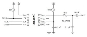
Now let’s take a look at a simple circuit using the Microchips MCP4921 12-bit DAC. (Click on images to get higher resolution.)

spi_dac_schematic

Three signals control the DAC: Slave Select (SS/Pin D9), Master Out Slave In (MOSI) and Serial Clock (SCK). Data is sent to the DAC through SPI’s bit serial protocol. First, SS is driven LOW, then 16 bits are sent one at a time to the DAC. SCK synchronizes the data bits sent via MOSI. The first byte consists of a 4-bit “command” and the top 4 bits of the 12-bit value to be converted. The second byte is the lower 8 bits of the value to be converted. After sending 16 bits, the SPI master drives SS HIGH. If you’re curious about all of the signaling details, please see the MCP4921 data sheet.

The rest of the DAC circuit consists of a voltage reference for the converter and a post-conversion (reconstruction) filter. The filter is a simple, one stage passive low pass filter with a 10,600Hz corner frequency.

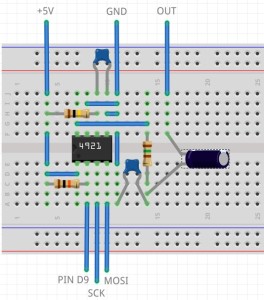
I built the DAC circuit on a small solderless breadboard. Here’s the layout.

spi_dac_breadboard

I connected MOSI, SCK, +5V and ground to the appropriate ICSP pins on the Arduino module. Slave Select is sourced by Arduino pin D9. I connected a littleBits Proto module to D9 and routed the input signal to the breadboard. If you want to postprocess the DAC’s audio output with littleBits modules, then route the DAC output to the Proto module’s output snap. Be sure to remove the shorting block (jumper) between the middle two pins on the Proto module. This approach provides power and ground to the audio postprocessing modules connected to the output snap of the Proto module — an important side-benefit.

The choice of pin D9 for Slave Select was the beginning of a long, hard journey in debugging. To make a long story short, pins D5 and D9 are buffered and the output buffer introduces additional delay on the Slave Select signal. The delay is long enough such that the DAC does not see a low Slave Select signal before data bits start arriving.

Here’s the code that writes the DAC:

#define NOP asm volatile ("nop\n\t")
void busyWait(uint8_t count) { 
  for(uint8_t i = count; i > 0 ; i--) { NOP ; } 
}

void writeDac(int16_t dacValue) {
  byte data ;
  SPI.beginTransaction(SPISettings(20000000,MSBFIRST,SPI_MODE0)); 
  digitalWrite(SlaveSelect, LOW) ;
  busyWait(25) ;
  data = highByte(dacValue) ;
  data = 0x0F & data ;
  data = 0x30 | data ;
  SPI.transfer(data) ;
  data = lowByte(dacValue) ;
  SPI.transfer(data) ;
  digitalWrite(SlaveSelect, HIGH) ;
  SPI.endTransaction() ;
}

The busy wait effectively stops the sketch for a little while after driving Slave Select LOW. This gives the Slave Select more time to reach the DAC before the sketch transfers the first data byte to the DAC. If you use an unbuffered pin like D1, you don’t need the busy wait.

It took a long time to eliminate all of the other possible issues that could have caused a failure: bad solder joints, wiring mistakes, etc. Fortunately, I have a similar DAC — the MidiVox — which works correctly. I also tested the hardware with Arduino UNO where all digital pins are unbuffered. It was frustrating to get everything working with the UNO, but not the littleBits Arduino module! Persistence wins the day.

In closing, I want to warn developers who interface high speed logic to littleBits Arduino. Beware of the delay through those buffered outputs! The delay may be long enough to throw off critical timing.