At some point, you’ll want to go beyond the few inputs and outputs provided by the littleBits Arduino bitSnaps.
The stock littleBits Arduino module has twelve unpopulated signal pads:
- Three analog inputs: A2, A3 and A4.
- Three digital inputs/outputs: D10, D11 and D13.
- Six ICSP signals: GND, MOSI/D16, VCC, RESET, SCK/D15, and MISO/D14.
Three of the ICSP pads can be used as ordinary digital inputs/outputs: D14, D15, D16. The same three ICSP pads also implement the Small Peripheral Interface (SPI): MOSI, MISO and SCK.
         GND ---O  O--- RESET
    MOSI/D16 ---O  O--- SCK/D15
         VCC ---O  O--- MISO/D14
The first article in this short series discusses the ICSP pads and how to solder a 2×3 header to the pads. The second article describes a circuit and code for a SPI-based digital-to-analog (DAC) converter using the Microchips MCP4921 integrated circuit.
The MCP4921 requires an active-low chip select (also known as “Slave Select”) signal to activate data communication with the SPI master (the Arduino). As described in part 2, I generated chip select through one of the bitSnap digital pins: D1, D5 or D9. D5 and D9 are buffered by a relatively slow-acting op amp. The op amp effectively imposes a delay on the chip select signal necessitating a long busy wait in the DAC’s interrupt routine. Pin D1 is not buffered, doesn’t require the busy wait and is faster.
Pin D1 itself does double duty. Depending upon its configuration, pin D1 functions as either an ordinary digital output or as the serial data output (TX). My latest project incorporates MIDI input and uses the Arduino MIDI library to parse and dispatch MIDI messages. After much experimentation and frustration, I determined that the MIDI library just doesn’t know how to keep its paws off pin D1 (TX). Even with MIDI THRU turned off (i.e., calling MIDI.turnThruOff()), the library seems to interfere with D1/TX. The interference disrupts communication with the MCP4921 DAC. Sending chip select by D5 or D9 is too slow, so it became time to populate the rest of the Arduino’s input and output pads.
We need two 1×3 pin headers to finish the job. I bought 1×3 pin headers from Jameco. In order to save time and money, you could just cut two 1×3 headers from a long header strip instead. Once again, I used a solderless breadboard as a jig to hold the headers in place while soldering. Here’s a tip (pun intended). Apply pressure to the side of each pin with the soldering tip; do not push down on the pin. If you push down, the pin may sneak down into the through-hole!
The 1×3 pin headers and the finished Arduino module are shown in the picture below. (As always, click on images for higher resolution.) With the 1×3 header pins soldered in place, I connected the MCP4921 chip select to Arduino pin D10 using a male-to-female jumper wire and changed the sketch to toggle D10.
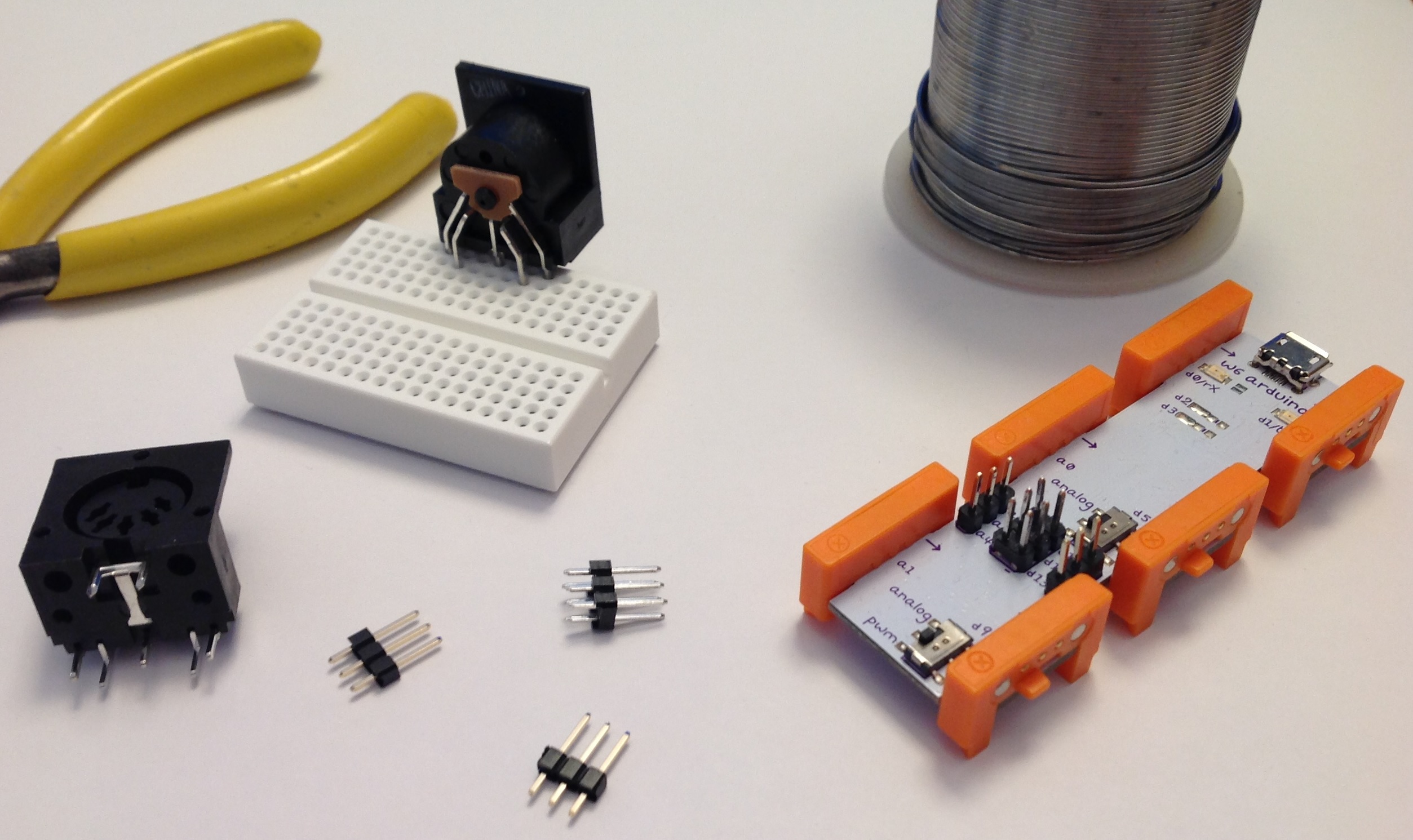
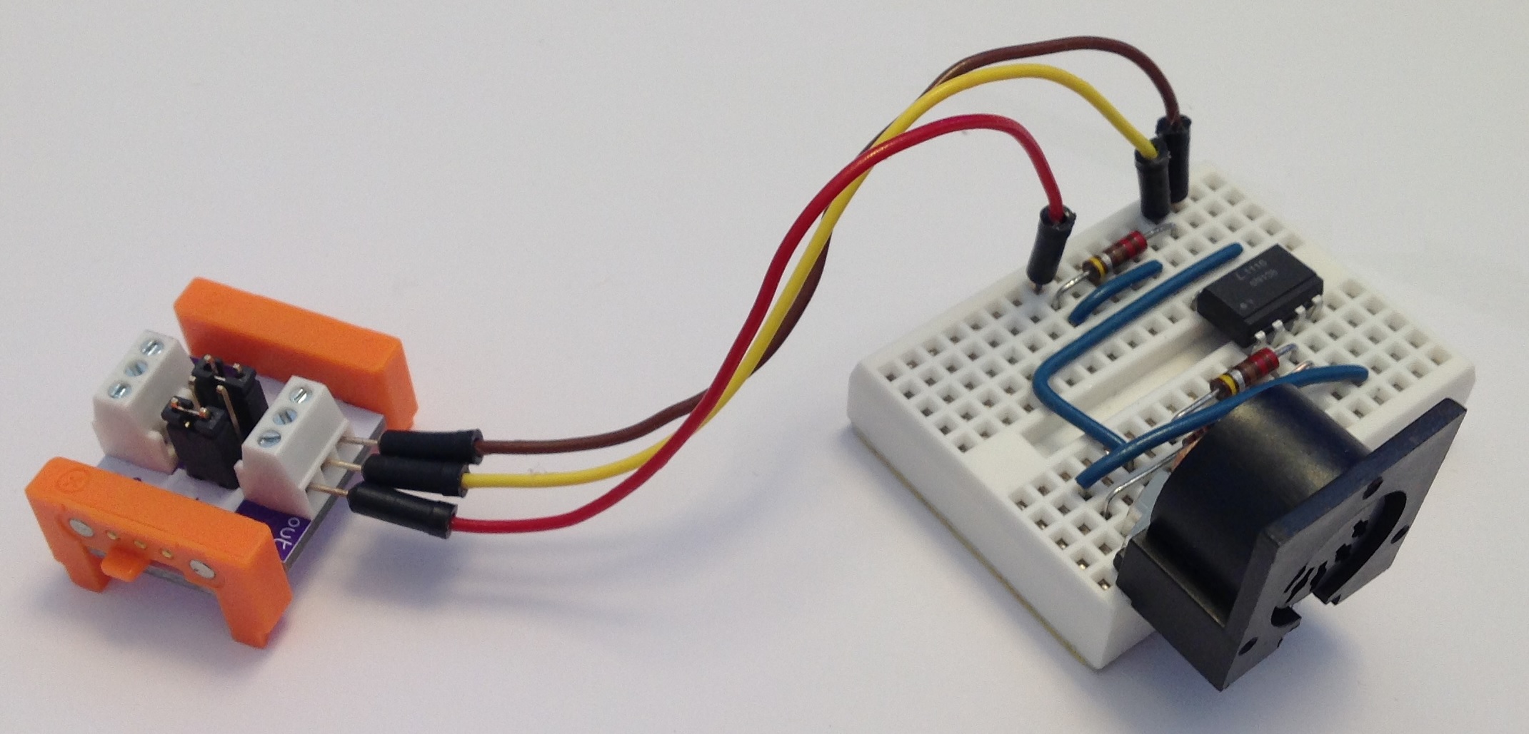
When I was searching for the headers, I came across “breadboard friendly” 5-pin DIN sockets sold by Adafruit. Adafruit charges a pretty penny for these sockets, but they are well worth it. With the success of the SPI DAC implementation, I decided to build the MIDI input interface on a small solderless breadboard (picture below). These small 170 point breadboards are so inexpensive, there isn’t much need to build on a prototyping board.
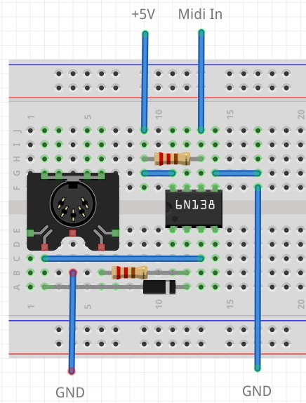
Here are the schematic and broadboard layout for the MIDI input interface. Have fun!