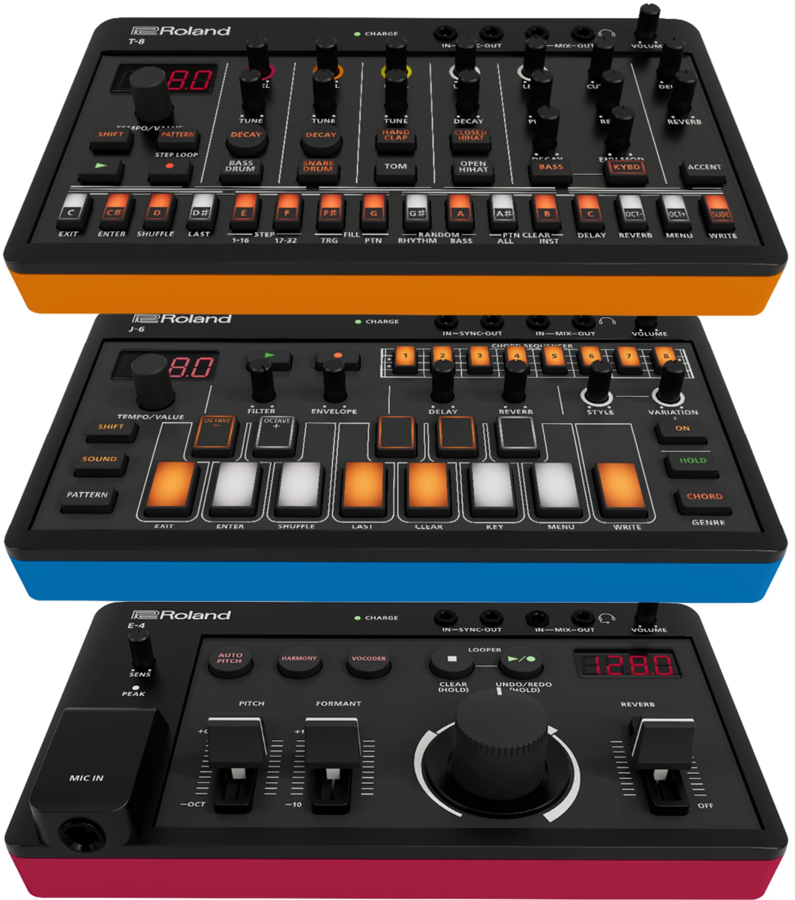
Roland’s new Aira Compact modules are a license to print money. Korg have successfully mined the low-cost, small module field with its Volca series. Now Roland have joined the fun. (“Aira” is pronounced “eye-ra”. OK.) These suckers are tiny!
Roland Aira Compact: T-8, J-6, E-4
There are three initial modules in the range:
T-8 Beat Machine
J-6 Chord Synthesizer
E-4 Voice Tweaker
I recommend Roland’s overview video. All of the modules have a built-in Li-ion battery (4.5 hour estimated operational time) charged via the micro-USB port. Throw in MIDI and SYNC, too, through mini-jacks.
Roland are smart to capitalize on their reputation in drum machines. The T-8 is a seven track machine: six rhythm tracks plus a TB-303 bass track.
The J-6 has a host of in-built chords and chord patterns organized into “Genres.” The interface seems to be well-thought out, especially for those less interested in theory and actually jamming black and whites. The J-6 has a 4-voice Analog Circuit Behavior (ACB) Juno-60 synth engine. The J-6 can be played from an external controller.
The E-4 Voice Tweaker is designed for voice mangling, but one should be able to run either signals into it, too.
The modules are hitting the street at $200 each. Somehow these kinds of modules find a way onto the studio. Almost by themselves…
Korg
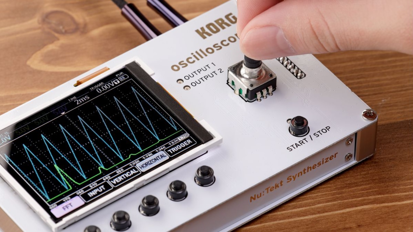
As cute and colorful as the Rolands may be, The new Korg NTS-2 is at the top of my short-list.
The Korg NTS-2 joins the NTS-1 mono synth in the Nu:Tekt product line. The NTS-2 is an attractive looking four channel oscilloscope. Punters are complaining about the price — $230 USD — but the this is a nicely featured oscilloscope plus tuner, plus FFT, plus spectrum analyzer. The NTS-2 has dual waveform generators which can act as add-on synth oscillators or LFOs. There’s some real development cost behind this thang.
Korg NTS-2 Oscilloscope
In terms of function, screen size and build quality, it beats my Gabotronics Xminilab Portable. The NTS-2 has a larger color screen and five soft function buttons. I’ve never been very successful with the Gabotronics as a stand-alone test instrument, so I’m hoping for better out of the NTS-2.
Unlike the NTS-1, the NTS-2 OSC can run on two AAA batteries (estimated two hours of operational time).
The NTS-2 will be bundled with a book: “Patch & Tweak With Korg” by Kim Bjørn (BJOOKS). The bundle is stamped “Limited Edition,” so Korg may eventually release NTS-2 on its own. Other books in the Patch & Tweak series cost about $45 USD. Maybe the NTS-2 alone will run $180?
Another consideration is test leads and probes. Korg assume the NTS-2 will be connected into your rig with patch cables. Korg do not mention probes, so if you need in-circuit measurements, you’re on your own. (Minor bummer.)
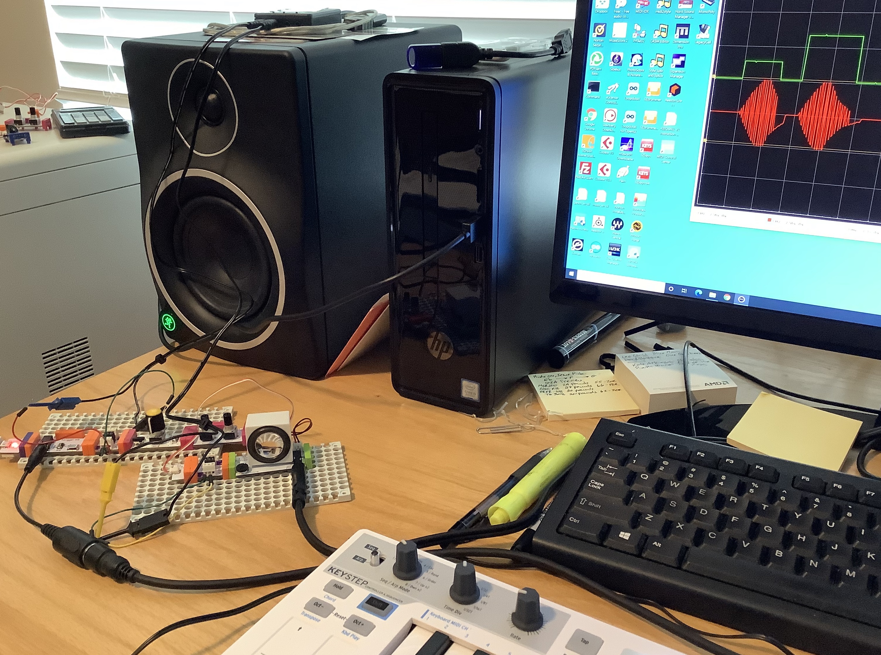
Here are a few experiments testing littleBits audio post-processing. In the first few cases, audio is produced by a Yamaha SHS-500 synthesizer fed into the LINE IN of a littleBits Microphone module. Outgoing audio is sent through a littleBits Speaker module connected to an external amplified speaker.
I did not draw the littleBits Power module into every example circuit. If you’re experimenting at home, hey, “One, Two, you know what to do…”
The first circuit filters incoming audio:
          PowerSnap
              |
              V
           Envelope <-- Button <-- PowerSnap
              |
              V
    Mic --> Filter --> Speaker
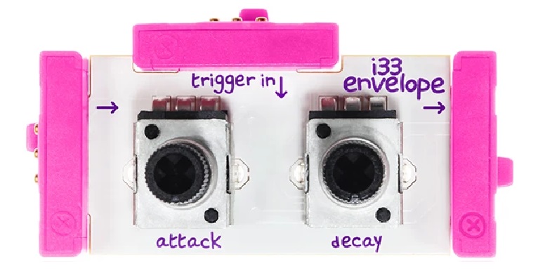
The Filter modulation input is driven by a littleBits Envelope module. The (audio) input of the Envelope is connected to a littleBits PowerSnap which supplies a constant +5 Volts to the input of the Envelope. A littleBits Button module is connected to the Envelope’s trigger input. (The second PowerSnap assures a full 5 Volt ON signal through the Button.) The Envelope sweeps from 0 to 5 Volts when the Button is pressed. Of course, the Envelope is shaped by its attack and release settings.
The first circuit operates successfully. The audio is filtered according to the Filter’s cut-off and resonance settings. The Filter quacks (a very scientific term!) when the Button is pushed.
The second circuit replaces the Button with a littleBits Pulse module:
          PowerSnap
              |
              V
           Envelope <-- Pulse <-- PowerSnap
              |
              V
    Mic --> Filter --> Speaker
The Pulse module repeatedly sends a trigger signal to the Envelope module. The triggers cause the Filter to quack correctly. However, there is an audible click when the Pulse module fires — even if no audio is playing. This noise is unacceptible and I don’t know why it is occurring. Power glitches perhaps?
At this point, I began experimenting with the littleBits Threshold module. The (third) simple test circuit below:
Power --> Dimmer --> Threshold --> Number
demonstrated that my intuition about the Threshold behavior is correct: when the voltage into the Threshold exceeds the threshold setting, the Threshold turns ON and outputs +5 Volts. When the input voltage falls below the threshold setting, the Threshold output turns OFF (0 Volts).
Testing tip: The Number module has a “Voltage” setting in which Number displays the incoming input voltage. You can use a Number module as an in-circuit volt meter.
Given that, I couldn’t determine why the Threshold was not acting like a gate generator when driven by a littleBits audio signal, i.e., driven by the Microphone module in its “Sound” setting. Turns out, the littleBits Microphone module converts the incoming LINE IN signal into its own notion of audio — a signal centered around 2.5 Volts. I connected a Bargraph (or Number) module to the output of Microphone, and indeed, the Microphone sends 2.5 Volts when the audio is silent.
Arg! Once again bitten by the lack of signal documentation! When the Microphone is in its “Other” setting, it converts the input signal to swing from 0 to 5 Volts. Bad news, however. The Speaker module expects audio in the 2.5 Volt centered, littlebits convention and it distorts like a bandit when driven with the “Other” setting.
The 2.5 Volt convention also explains why some folks have observed only a 2.5 Volt sweep in the Envelope output. All of this has serious implications when mixing audio and control signals in littleBits. I need to think about this for a while…
The fourth test circuit demonstrates filtering of regular line level audio:
                              Powered Speaker
                                  LINE IN
                                     |
    Power --> Proto --> Filter --> Proto
                |
           Synthesizer
            LINE OUT
This circuit filters incoming audio. Fortunately, the 2.5 Volt convention does not preclude a simplified signal chain, that is, a chain omitting the littleBits Microphone and Speaker modules. A filter is a filter is a filter, I guess.
Although the Filter module operates on a “regular” audio signal, the Delay module does not. Substituting the Delay module into the fourth test circuit produces nasty noise and a whine. It will process the audio (you can hear repeats, etc.), but the noise/whine is horrible. Screams like a banshee. Bummer.
Bottomline, the littleBits Filter module has potential as an add-in for a PSS-A50 mod (or any other mod) without Microphone and Speaker modules. The littleBits Delay is simply too noisy by itself; one needs the Microphone and Speaker to perform signal conversion. As to the Filter, I need to explore alternatives for modulation. Experiments with using the Oscillator module as an LFO were underwhelming. So far, I haven’t successfully cobbled together an envelope following or audio-trigger envelope. Stay tuned.
I’m still thinking about Yamaha PSS mods, most notably, the PSS-A50. Open box A50s are coming on the market and I get the itch to modify an A50. I don’t want to buy a brand new unit since I will immediately tear into it with a screwdriver, drill, and worse! 🙂 Here’s a few more thoughts.
After looking at the PSS-E30 Remie teardown, that speaker has got to go. Even without the speaker, I don’t think there is enough room for the Korg NTS-1 as I first planned.
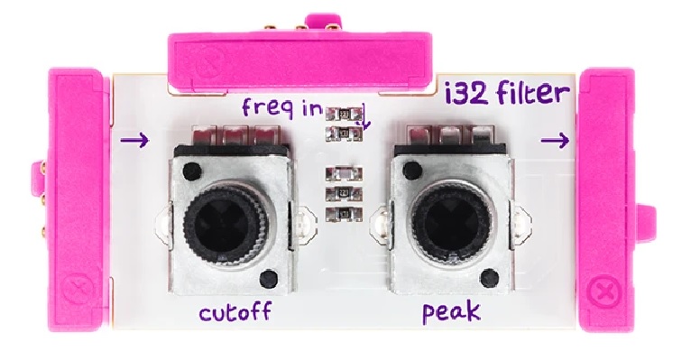
littleBits filter module
Second-besties, I’m considering a littleBits solution. Lots of folks mod the Korg Monotron to get access to its filter, but oddly, they don’t consider the littleBits filter module. I did a few preliminary experiments with the filter and delay modules using the Yamaha SHS-500 Sonogenic as a stand-in for the PSS-A50 sound generator. The filter and delay sound great although I need to add an envelope generator to make the filter quack and bark.
My main concerns at this point are:
Driving littleBits audio without the Microphone module and the Speaker module. Both modules would take up unnecessary space. I’m just don’t know (yet) if regular headphone levels are strong enough for the littleBits 0 to +5 Volt signaling convention.
Physically and electrically securing the littleBits modules to themselves and the A50 chassis.
Finding 5 volt power in the A50 in order to supply the litleBits modules.
Of course, there’s the problem of mounting the littleBits modules so that the controls (potentiometers) poke through the A50 speaker grill.
I investigated the PSR-F50 audio and digital electronics. The PSS audio amp is mostly likely different than the F50. So, I need to get the A50 service manual. The service manual should help me find the +5 Volt rail, too.
I took another look at the Yamaha YMW830-V processor pin-out. The YMW830-V is also known as the “SWLL” processor. It is a system-on-a-chip (SOC) containing the CPU, memory, and tone generator. The SWLL has five pins (TRST, TDI, TMS, TMS, TCK, and TDO) for serial input/output — most likely USB. This doesn’t bode well for people who want to add 5-pin MIDI to the A50 (or other SWLL-based keyboards).
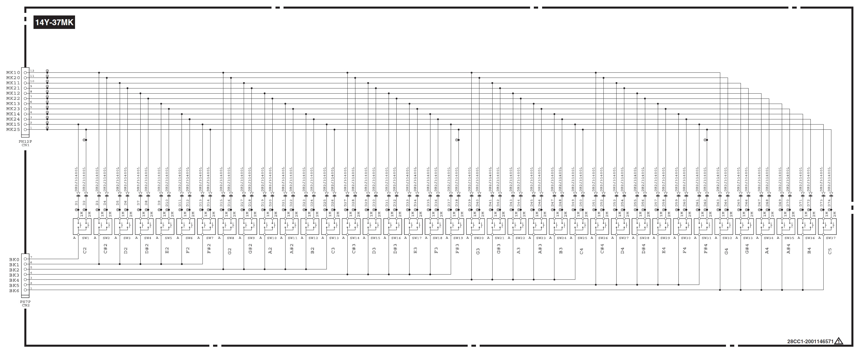
Reface YC key scan matrix
The PSS series, the Reface series and the SHS-500 share the same 37-key keybed. The key switch matrices are similar. They all break the key range into groups of six keys. Each keybed is a 6 group by 6 key matrix with a dedicated group to scan the fourth C key. The PSS and Reface/SHS differ in the number of key contacts as the Reface/SHS are velocity sensitive and the PSS is not. The Reface/SHS have two contacts per key and the PSS has one contact per key. The Reface/SHS have a total of twelve sense lines (2 lines per key) while the PSS has only six sense lines.
6×6 must minimize ribbon cable width or something because Yamaha will subdivide 61 keys into upper and lower banks in order to deploy six keys per group with 6 groups per bank maximum. You’ll see this practice in the synth product line, too. Just sayin’.
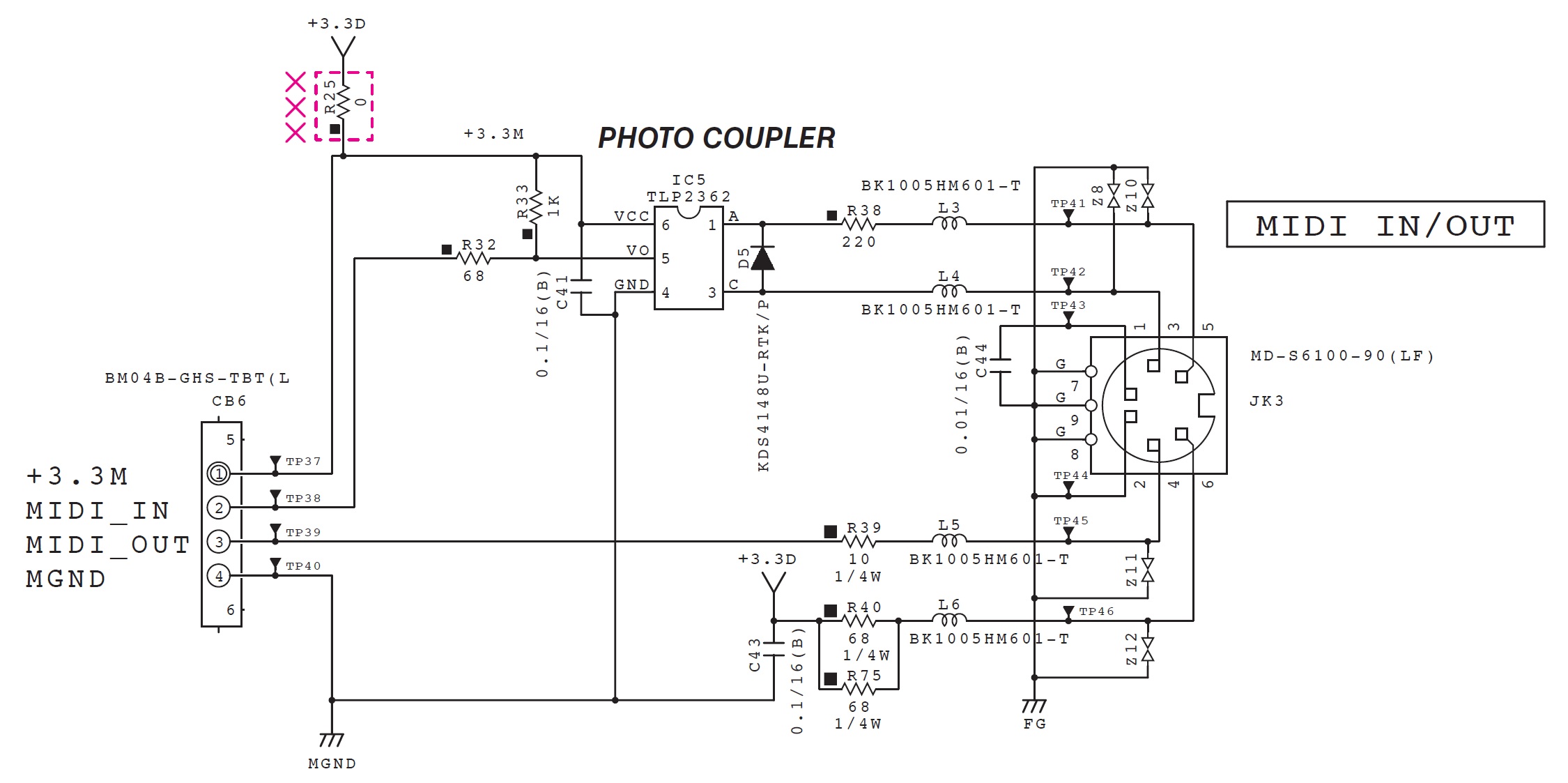
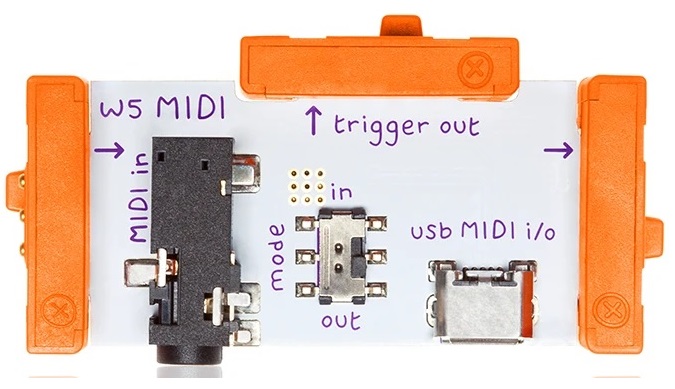
The Yamaha SHS-500 and Reface series use the same MIDI I/O dongle. I came across this rather nice diagram (below) of the SHS’s MIDI port. It should help you to whip up a custom cable or two. [Click image to enlarge.]
My last blog post took a look at the Pitch and Gate control voltages (CV) generated by the Arturia Keystep. Keystep’s Pitch and Gate behave conventionally. I also took note of how they differ from the littleBits gate CV signal, which combines pitch and gate control into a single signal. I mentioned two potential approaches for interfacing Keystep to littleBits:
Driving littleBits with Keystep’s Pitch and Gate, and
Sending MIDI to a littleBits MIDI module that handles conversion to littleBits gated CV.
I tried each approach. Here’s what I learned.
Keystep Pitch and Gate circuit
In this approach, the littleBits Oscillator is always running, always generating an audio signal. The Oscillator tracks the Gate voltage generated by the Keystep. The trick is opening up and shutting off the audio signal. For that, I put a littleBite Envelope module after the Oscillator and triggered the Envelope with the Keystep Gate voltage.
The resulting circuit is:
            Keystep Pitch                Keystep Gate
                  |                           |
                  V                           V
    Power --> CV Module --> Oscillator --> Envelope --> Speaker
The Keystep Pitch output is connected to the “CV IN” connector on the CV Module. The CV Module routes the incoming control voltage to its output, which sends the pitch control voltage to the Oscillator Module. The Keystep Gate output is connected to the Envelop’s Trigger input.
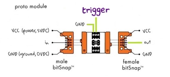
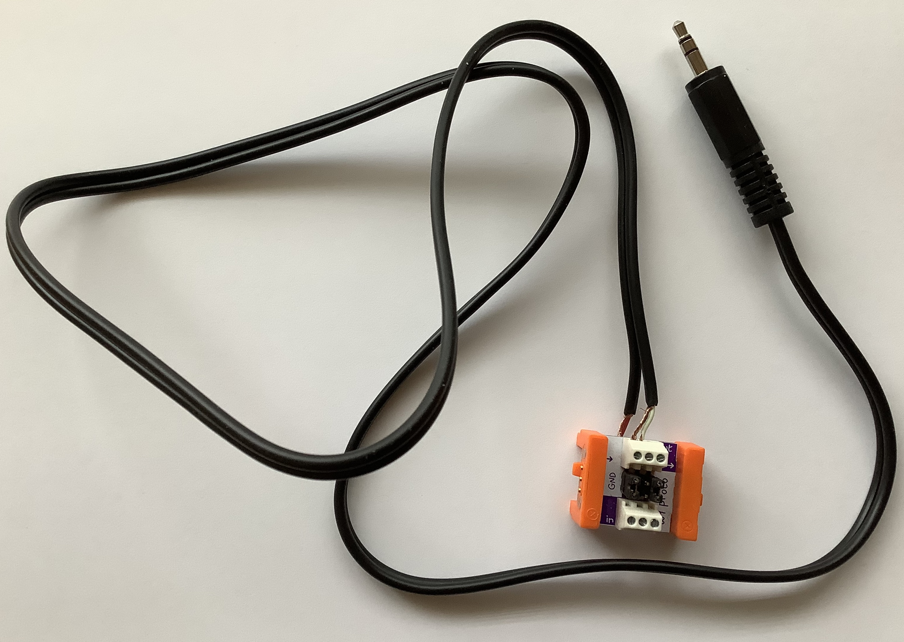
littleBits Proto Module ins and outslittleBits Proto Module and quick-and-dirty patch cable
The Pitch output to CV IN connection is a standard 3.5mm patch cable. But, how is the 3.5mm Gate jack connected to the Trigger bitSnap? The littleBits Proto Module provides the solution. I cut a (stereo) patch cable in two and connected the shield and tip wires to the littleBits Proto Module as shown above. The Proto Module sends the incoming trigger signal (the Keystep Gate) to the output bitSnap. From the output bitSnap, the trigger signal goes to the Envelope Trigger input.
Properly, I should have used a mono patch cable, but I didn’t have one to sacrifice. I connected the TIP and SHIELD wires, leaving the RING unconnected.
That’s the entire setup! For testing purposes, I attached oscilloscope probes to the trigger (Keystep Gate) and the Envelope’s audio output. I also verified correct operation at intermediate points along the main signal path.
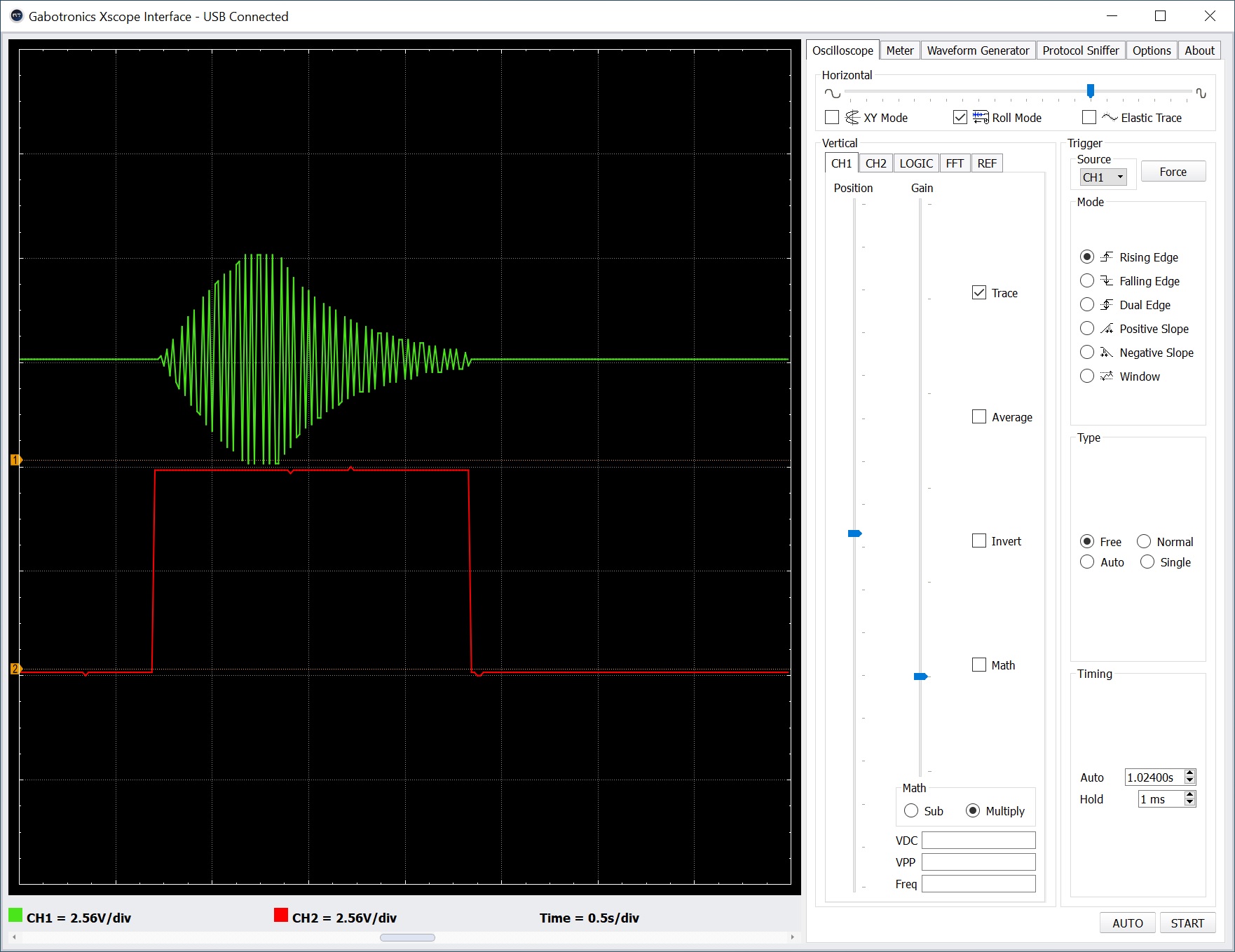
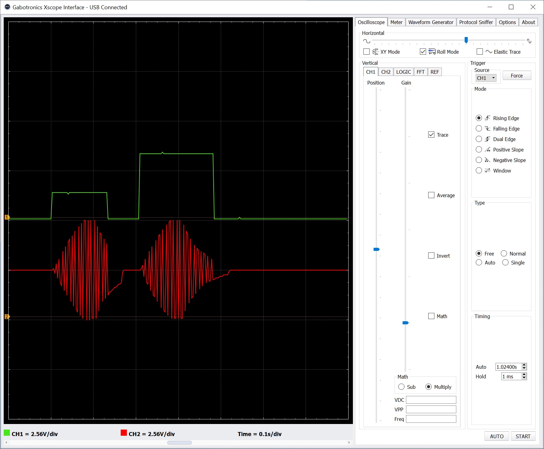
Oscillator audio (top) and Keystep Gate (bottom)
The screenshot above shows two oscilloscope traces. The top trace (green) is the final audio signal. Note the attack-release envelope around the oscillator signal. The bottom trace (red) is the trigger (Keystep Gate) signal. If the trigger is dropped before the entire envelop completes, the audio cuts off (i.e., it’s truncated). If the trigger is held beyond the combined attack plus release time, the audio signal merely stays at zero. The audio signal remains shut off until another trigger (the rising edge of Gate) is received.
Although this circuit gives us the desired behavior, it wasn’t easy getting things to work reliably. I seemed to suffer more than the usual loose connections and other lab-bench gremlins.
           Keystep MIDI OUT
                   |
                   V
    Power --> MIDI Module --> Oscillator --> Envelope --> Speaker
MIDI arrives on the MIDI Module’s 3.5mm connector instead of the USB port. Otherwise, the main signal flow is the same.
Keystep/littleBits test rig
I monitored the gated CV signal produced by the MIDI Module and the audio signal generated by the littleBits Envelope using the oscilloscope. I played two notes in quick succession. The second note is two octaves higher than the first note.
littleBits audio triggered by MIDI Module
In the screenshot above, the top oscilloscope trace is the gated CV signal. The bottom trace is the synthesized audio. Not any different than the Pitch and Gate control volltage approach, eh?
Since the final audio is much the same, I would go with the MIDI Module circuit. It is simpler and its wiring is less touchy. The circuit uses the littleBots modules pretty much as intended by the littleBits engineers.
The MIDI Module approach makes the Keystep Pitch, Gate and MOD outputs available for other duties such as key-scaling (i.e., varying the effect of a sound modifier by keyboard pitch), modulation and user control. Don’t forget to insert littleBits Dimmer Modules (potentiometers) along control paths in order to set modulation level and so forth.
Today’s post continues with Arturia Keystep. Although the Keystep Gate and Pitch control voltage (CV) signals are conventional, I wanted to visualize them with an oscilloscope. I strongly recommend getting an oscilloscope when working in modular synthesis because pictures/graphs help understanding. [We haven’t even gotten to the audio yet!] I connected the Gabotronics Xminilab oscilloscope to the Keystep’s Gate and Pitch CV outputs and took a quick look.
First thing I noticed was a 12V positive trigger level. Holy smokes, I hope I didn’t apply that high signal to littleBits way back when! littleBits modules operate in the 0V to 5V range. Fortunately, littleBits input ports have an ON Semiconductor ESD9L5.0ST5G ESD suppressor/TVS diode, which protect against ESD and transient voltage events. Still, it’s better to configure voltages correctly ahead of time and not risk an accident.
Second thing is that Keystep CV voltages cannot be configured through its front panel. That’s somewhat understandable in a low cost product like Keystep. Control voltages are configured by Arturia’s MIDI Control Center (MCC) software — a free download for Keystep owners.
Here is the control voltage configuration that I used during testing:
MIDI CV output: Volt per octave
0V MIDI note: C1
Note priority: Last
MOD CV source: Mod wheel
MOD CV max voltage: 5V
Pitch bend range: 2 semitones
Gate CV output: V-trig 5V
Keystep supports V-trigger 12V and S-trigger in addition to V-trig 5V. S-trigger is the old Moog convention that is not used very much anymore. It’s sometime called “negative trigger,” but it’s really a strange creature requiring a special connector.
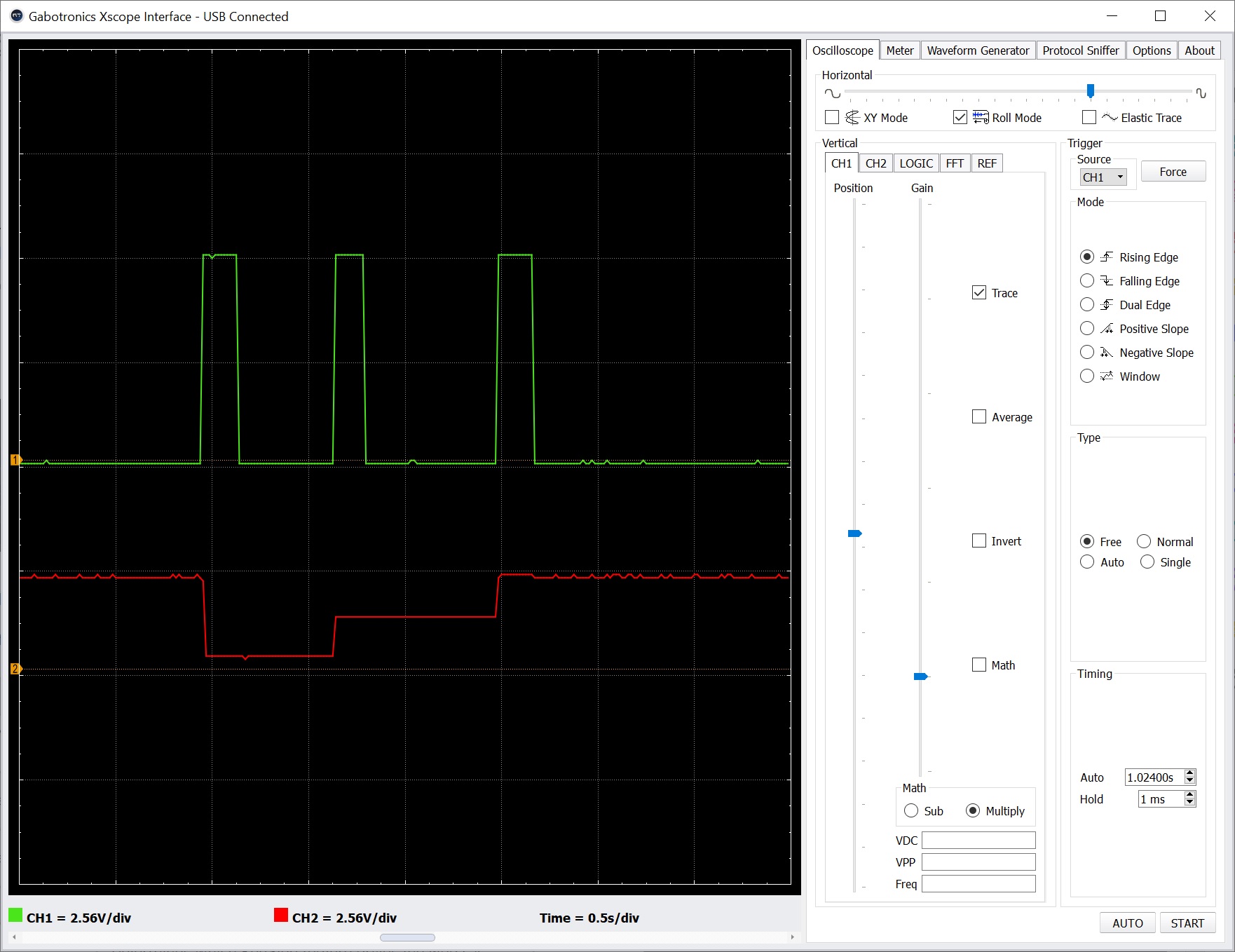
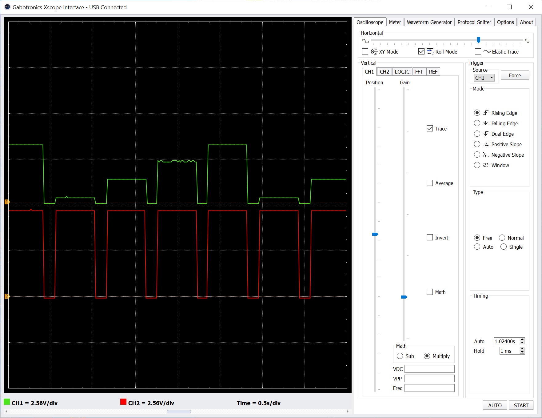
Keystep Gate (green) and Pitch (red) control voltages
The screenshot above shows the Keystep in action. [Click image to enlarge.] The top trace (green) is the Gate (V-trigger 5V) output and the bottom trace (red) is the Pitch output. The Gate signal is, er, a gate. It goes high when a key is pressed, stays high while the key is held, and goes low when the key is released.
In the example, I played three notes where each note is an octave apart. The vertical oscilloscope scale is 2.56V per grid division. Each step up in the bottom trace (Pitch) is about 1V. Also, you see the Gate signal hit a maximum 5V.
In the future, I may need to tweak Keystep’s 0V MIDI note parameter if I drive the littleBits Oscillator module with the Pitch signal. One needs to find a happy operational sweet spot between Keystep octave transpose and note range versus the limited 5 octave range of the Oscillator module. Keystep’s Pitch signal ranges from 0V to 10V, and I don’t want to drive the littleBits Oscillator with more than 5V, if possible. MCC does not allow us to specify a maximum, do-not-exceed Pitch voltage.
One way around the pitch voltage issue is to control the littleBits Oscillator via the littleBits MIDI Module instead. In that case, the Keystep 5-pin MIDI OUT connects to the MIDI Module (mode switch set to IN) over a Korg convention, 5-pin to 3.5mm adapter. (The O-Coast adapter adheres to the same convention and works, too.) With the MIDI approach, we don’t need to worry about over-driving the Oscillator module with a high, out-of-range voltage. The littleBits MIDI module tops out at 5V.
I have both the littleBits MIDI module and littleBits CV module. Thus, I can drive littleBits oscillators via MIDI and send the Keystep MOD CV to the littleBits CV module for modulation duties. With the Keystep MOD CV max voltage set to 5V, I should be safe. If I need to reduce the MOD CV range further, I can always run the output from the littleBits CV module into a littleBits dimmer (potentiometer) and attenuate the level.
The MIDI module approach also produces the gated CV signal expected by littleBits oscillators. The Keystep Pitch output provides a simple, steady voltage level and doesn’t have an in-built gating function. When you hit a key, the Keystep changes the Pitch output voltage accordingly and the Keystep holds that voltage even when the key is released. If connected to a littleBits Oscillator, the Oscillator will never see a release event, that is, the Pitch voltage never drops to 0V when a the key is released. The littleBits Oscillator merrily continues to play! On the other hand in littleBits-world, the gated CV drops to zero. Thus, littleBits combines pitch control and trigger (gate) into a single signal.
One could build a simple converter from separate gate and pitch CV to the littleBits gated CV. I’m thinking of a voltage-controlled SPDT analog switch like the Texas Instruments TS5A9411 (or MAXIM MAX4544, etc.). The trigger (gate) signal controls the switch. When the trigger is low, the signal connects to ground and passes 0V. When the trigger is high, the switch passes the Pitch CV signal.
Another possible work-around is to follow the littleBits Oscillator with an Envelope module and connect the Envelope’s trigger to the Keystep Gate output through a littleBits CV module. [Whew!] The Envelope should pass and shut off the Oscillator’s sound when the gate is asserted and dropped, respectively. I’m going to give this idea a go.
The littleBits Envelope Module is rather basic with only attack and release controls (no decay or sustain controls). The module has two inputs:
The primary input at the left end of the module typically receives the audio to be shaped by the envelope.
The trigger input receives an (alternative) trigger signal.
The Envelope Module triggers in one of two ways:
When the primary input transitions from zero to a positive voltage.
When the trigger input transitions from zero to a positive voltage, usually 5 Volts.
Allowing the primary input to trigger envelope generation simplifies connection. It is also easier to use conceptually. A beginner doesn’t need to understand envelope generators, voltage controlled amplifiers and how the two interact. A beginner doesn’t need to wire in a separate envelope generator. Everything happens along a single audio signal path and “it just works.”
The simple circuit below is all one needs to get started with synthesis:
Power --> MIDI --> Oscillator --> Envelope --> Speaker
If you have is the basic Synth Kit, then the MIDI Module may be replaced by the Sequencer Module or Keyboard Module. As we saw in the last post, the Gated CV output from the MIDI Module turns the oscillator ON and OFF (gate) and sets the oscillator pitch (CV). When the Oscillator is generating audio, the audio signal triggers the Envelope Module which shapes the audio amplitude. The shaped audio (now with attack and release segments) is finally sent to the speaker.
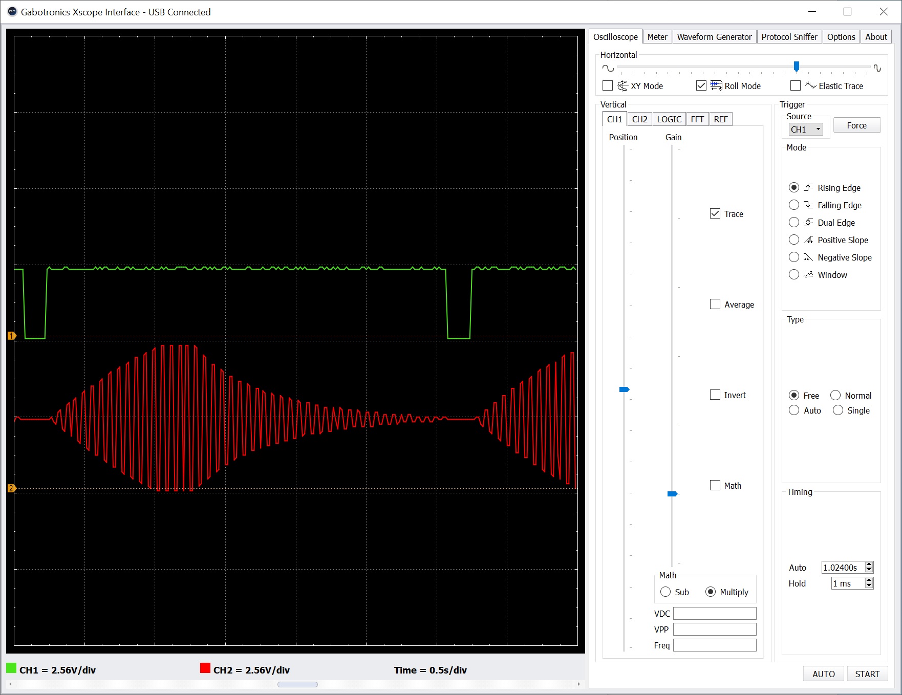
I connected this simple circuit to a dual trace oscilloscope. I found that the attack and release phases are sequential without an intervening sustain phase. The duration of the entire envelope is the sum of the attack duration and release duration. There isn’t a decay phase either. In other words, holding the gated CV longer does not sustain a note! The maximum duration of the attack phase is about 1 second and the maximum duration of the release phase is about 2 seconds.
Envelope Module in action (max attack and max release)
The oscilloscope traces above show the final, shaped audio signal when attack and release are set to maximum. [Click images to enlarge.] The top trace (green) is the gated CV signal from the MIDI Module. The bottom trace (red) is the shaped audio signal. Each horizontal grid mark is 0.5 seconds. Please note that the gate must be as wide as the attack duration plus the release duration to obtain the full contour.
littleBits Filter Module
Skipping ahead to the Filter Module for a moment, the Filter has an input which allows cutoff frequency modulation. In a typical modular synth, this input is tied to a separate envelope generator. In keeping with the littleBits “It just works” philosophy, you can drive the cutoff input with the audio signal as seen in the circuit below:
                                                ----
                                               |    |
                                               |    V
   Power --> MIDI --> Oscillator --> Envelope --> Filter --> Speaker
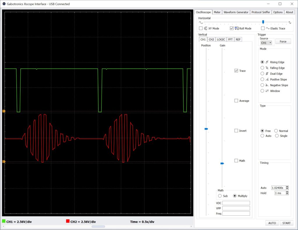
Yes, this actual works as shown in the oscilloscope traces below. The top trace is the gated CV signal from the MIDI Module. The bottom trace is the output of the Envelope Module which is connected to the Filter cutoff modulation input.
Modulating the filter with envelope shaped audio
littleBits envelope generator
I’ll bet that you’re wondering if the littleBits Envelope Module can be made into a conventional envelope generator. So did I. It would be great to have a conventional synthesis chain with separate envelopes for amplitude and filter with separate attack/release (AR) controls for each envelope.
Here’s one experimental solution:
               --> MIDI IN  --> Oscillator --> Filter --> Speaker
              |       |                           ^
    Power --> |       | Trigger                   |
              |       V                           |
               --> Envelope ----------------------
If you have a second Envelope Module, you can insert it between the Filter and Speaker Modules, forming a conventional OSC→VCF→VCA chain. I have only one Envelope Module and built the circuit shown above. I used a littleBits Split Module to send the Power output to the MIDI Module and Envelope Module. This is the ideal situation for powerSnaps, if you got ’em.
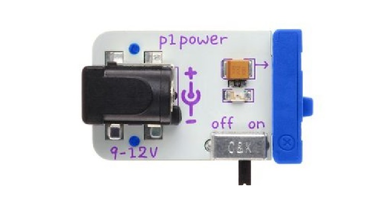
littleBits Power Module (old model)
How does this circuit work? The Power Module provides the +5V and ground power rails, of course. The Power signal output is tied to 5V. Thus, the Envelope Module sees a constant 5V signal at its primary input. The littleBits MIDI Module triggers the Envelope module. The envelope generator inside the Envelope Module triggers and shapes the constant +5V input signal into the familiar attack and release envelope contour.
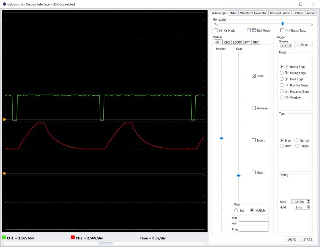
Output from the “pure” envelope generator circuit
The oscilloscope traces above show the gated CV signal (top/green trace) and the output from the Envelope Module (bottom/red trace). Yep, the final audio sounds exactly as expected having the familiar wah-wah filter funk. The final audio sounds cleaner when the filter cut-off frequency is modulated by the “pure” envelope generator.
One final detail. The internal littleBits envelope generator is based on a 555 timer circuit. If you’re curious about the internal design of this or any of the littleBits modules, be sure to visit the littleBits Eagle file repository where you will find schematics.
I got the itch to experiment with analog audio processing and finally unpacked the old littleBits synth modules. Folks hack the Korg Monotron series, so why not hack littleBits modules instead? The modules are inexpensive when compared with Monotron and are easily reconfigurable while experimenting.
Since I last wrote about littleBits (circa 2017), Sphero purchased the littleBits company in 2019. Fortunately, they retained the littleBits forum.
Not so good, neither Sphero nor littleBits provide precise documentation about synth module functionality or the input and output signal characteristics. Precise information is needed especially when interfacing modules with the outside world including module synth gear. Timing information, in particular, is needed.
We do know a few things about littleBits, however. littleBits modules normalize input and output signals to a 0 to 5 Volt range. Both digital and analog signals are normalized. Normalization facilitates the plug-and-play module architecture and you can freely interchange analog for digital and vice verse.
Background
Before diving in, here is a little background information about the signal types and terminology commonly used in modular synthesis.
“Control voltage (CV)” is an analog signal which controls continuous functions like oscillator pitch generation, envelope and filter modulation, etc. CV sweeps continuously across an operational range, e.g., 0 to 5 Volts.
“Gate” is a digital signal. It is an ON/OFF signal. A keyboard, for example, asserts gate when a key is pressed and drops gate when the key is released. Gate indicates a condition, e.g., a key is pressed. The leading and trailing edge of the gate indicates a change in the condition.
“Trigger” is a digital signal similar to gate. However, trigger is usually a short digital pulse. Trigger is intended to indicate an event, like a clock tick, not just the presence or absence of a condition. Trigger signals often control synchronization.
Of course, electrons are electrons and one is free to combine CV, gate and tigger in any manner. Not all mixtures are meaningful (useful), however.
Details about CV, gate and trigger vary from manufacturer to manufacturer. Moog, for example, use the linear Volts per octave convention. On the other hand, old Yamaha and Korg synths use the Hertz per Volt convention. Maximum and minimum voltages level may differ by manufacturer and so on.
My goal here is understanding the convention used by littleBits.
littleBits MIDI and oscillator modules
I decided to start from the front of the synthesis signal chain and work back. The first stage in the synthesis chain is the littleBits MIDI module. A close look at the MIDI module signals in action should tell us how littleBits implement basic synthesizer control (CV, gate and trigger).
littleBits MIDI module
The MIDI module has a USB-B device port that presents itself to the USB-A host as a class-compliant MIDI device. The MIDI module supports both USB MIDI IN and USB MIDI OUT. However, the module operates in one mode (IN or OUT) at a time. The mode is selected by its mode switch (duh!).
IN mode: Receives MIDI messages from the host.
OUT mode: Sends MIDI messages to the host.
This blog post focuses on IN mode.
IN mode converts incoming MIDI note messages to two signals:
Gated control voltage (gated CV)
Trigger
Although littleBits call the digital output “Trigger,” it really is a gate signal, as we shall see.
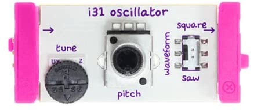
littleBits Oscillator module
The littleBits Oscillator module is a pretty simple affair. The sole input is the (gated) control voltage which changes the pitch. The sole output is either square or saw wave as selected by the waveform switch.
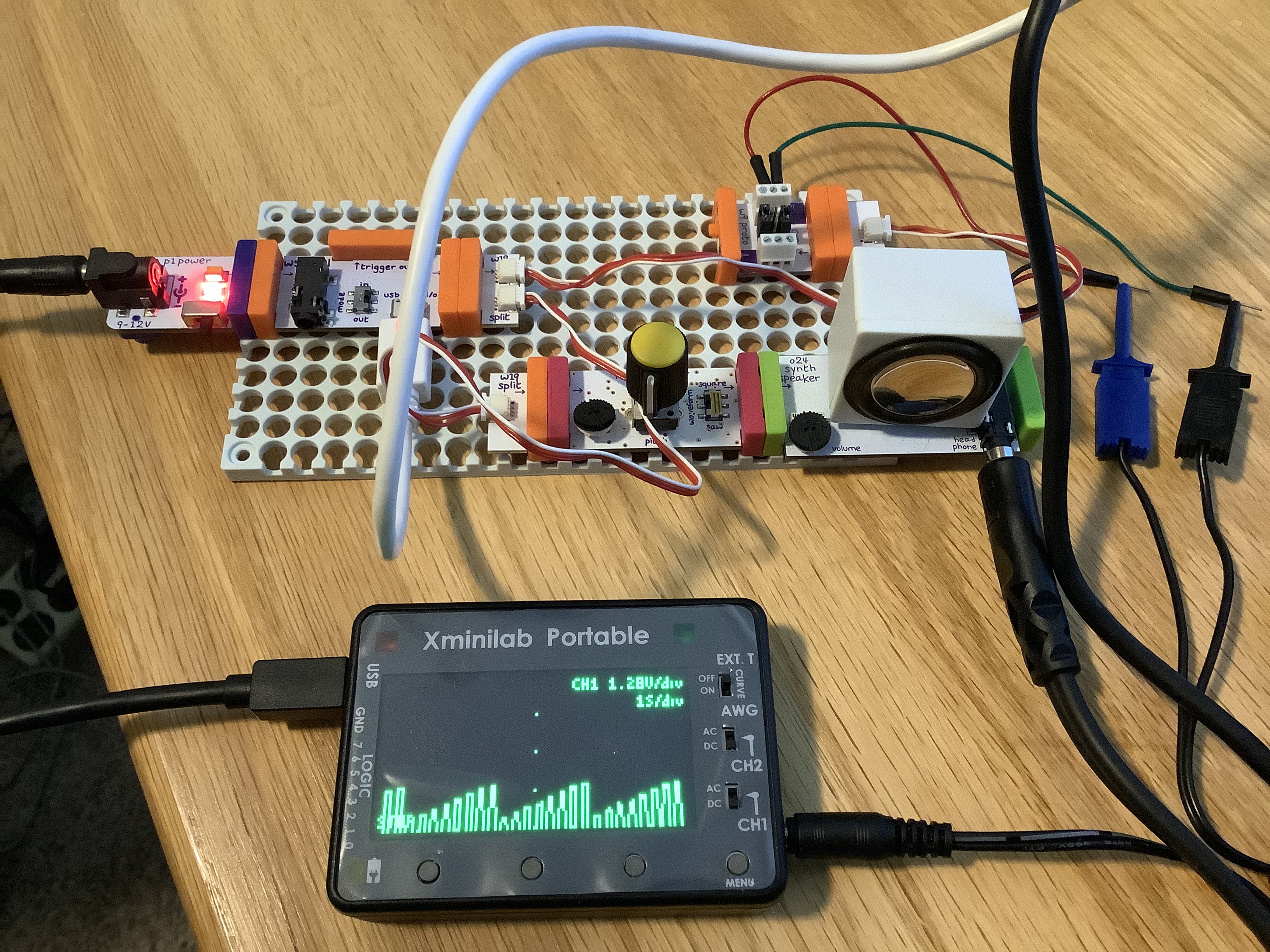
The test rig
Here’s my test and measurement approach.
The littleBits signal chain consists of a power module connected to the MIDI module which drives a littleBits oscillator module. I split the gated CV signal sending it to both the oscillator and a proto module. The oscillator output is sent to a speaker module, giving me aural feedback. Hey, is this thing on?
MIDI module/Oscillator test circuit
The GND and gated CV signal are sent from the proto module to a Gabotronics Xminilab oscilloscope. I attached another proto module to the MIDI module “trigger out.” The GND and “trigger out” from that proto module are went to the second channel of the oscilloscope. Thus, I can monitor both the gated CV and “trigger out” and see the timing relationships between the signals.
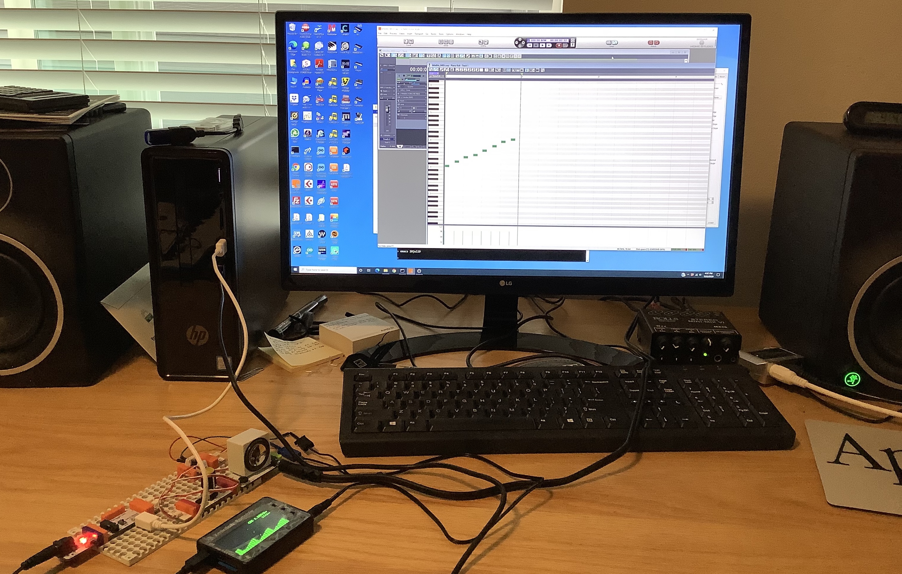
SONAR/Oscilloscope test rig
The Xminilab front panel user interface is a little fiddly. So, I connected the oscilloscope to a PC running the Gabotronix oscilloscope application. This arrangement makes it sooooo much easier to configure the oscilloscope and to capture screen shots.
The USB MIDI comes from the PC, too. SONAR generates MIDI messages and sends them to the littleBits MIDI module. Test messages are produced from a repeating one measure loop (80 BPM or so). The repeating loop gives me good repeatability.
The signals under test
As noted by other experimenters, littleBits combine gate with CV functionality. When the MIDI module receives a note ON message, it:
Asserts the trigger signal, and
Drives the gated CV output with a positive voltage proportional to the MIDI note number.
The MIDI note range is C2 to C6 (4 octaves). MIDI note C2 generates a gate CV voltage of 0.2 Volts. From there, the output voltage increases by 1 Volt per octave (1V/oct). Each semi-tone step increases the voltage by 1/12 Volts. The module asserts trigger by raising its output voltage to 5V.
When the MIDI module receives the corresponding note OFF message, it:
Drops the trigger signal to 0V, and
Drops the gated CV output to 0V.
Notice that the gated CV output is asserted and dropped in parallel with the trigger output. Trigger is always driven to 5V while the gated CV voltage is positive and is proportional to the MIDI note number.
The screenshot below illustrates the operation of these two signals. The top trace (green) is the gate CV voltage. The bottom trace (red) is the trigger voltage. [Click images to enlarge.]
Gated CV (green/top trace) and “trigger” (red/bottom trace)
The MIDI test loop plays C2, C3, C4 and C5 in succession and repeats. The stair steps in the top trace show the effect of each successive note in the loop. The vertical display scale is 2.56V per grid division. You can see that each successive step is 1 Volt higher starting with C2 at 0.2V.
The trigger and gated CV traces are in temporal lock-stop, i.e., they rise and fall together. The width of the trigger signal is always the same width as the gated CV signal. Please recall that “trigger” in synth-speak is normally a fixed-width narrow pulse. That’s why I think the littleBits “trigger” signal is really a gate signal.
So, why do littleBits use a gated CV? Short answer: In conventional use cases, both gate and CV can be sent through a single wire (connection). The synthesist doesn’t have to route two separate wires (connections). The simplified wiring makes life easier for novice users (kids). The synthesist merely lines up a keyboard (sequencer, MIDI module) with an oscillator module and “it just works.” We will see other instances of the “It just works” philosophy in the envelope module, too.
C2, C3, etc. are MIDI note numbers and nice names. However, you’ll need to tune the Oscillator module to obtain the correct musical pitch.
The prologue comes in 49- and 61-key models. I like the portability of 49 keys although the 49 ($1,499.99 USD street) is eight voices while the 61 ($1,999.99 USD street) is 16 voices. The industrial design looks quite appealing and inviting — can’t wait to actually try one.
Although I don’t own any modules in the volca range, the volca mix ($169.99 USD street) would make a very useful table-top utility module for analog experiments. In addition to a three channel mixer, the volca mix provides three 9V DC output jacks, tempo control and sync, and two stereo speakers. Would combine nicely with littleBits. (littleBits, I haven’t forgot ya. I’m just flat out of time!)
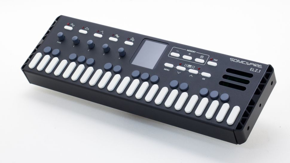
The Sonicware ELZ_1 compact synth is in the “too cool for school” category. It has multiple sound engines: FM, 8-bit wave memory synthesis, DNA Explorer (a waveform extractor and mangler), granular, standard oscillator and low-bit oscillator.
The ELZ_1 keys are dinky chicklets, but it’s really about small size and portability (15.7″ x 5.2″ x 1.8″, 2.2lbs, 4 AA batteries, built-in speaker). It doesn’t have 5-pin MIDI which is a shame, because with its small size, it would be great to MIDI it up with a full-size controller. (The world needs a $10 self-contained USB-B to 5-pin MIDI converter.) No word on price.
Nintendo are going maker — a nifty idea for extending the Nintendo Switch beyond gaming. Nintendo Labo kits are very low cost (cardboard!) maker kits. The Variety Kit includes a cardboard, Switch-driven toy piano. Teachers need to pick up on this one.
Just back from a long trip to Seattle. I had a great time seeing family, friends, old and new. Of course, there are always a few nerd-stops along the way.
I had the pleasure of visiting the Living Computers: Museum + Labs on the south side of Seattle. Just take the Sound Transit Link light rail system to the SODO station, walk a few blocks west along South Lander Street to First Avenue, and walk a few blocks north from there.
Seattle area public transportation is excellent. Be sure to pick up an ORCA transit card. Senior citizens can ride pretty much anywhere for $1!
Living Computers is both a hand-on museum and educational lab space. It’s another Paul Allen venture like the Museum of Pop Culture (once known as “EMP,” now “MoPOP”). The goal is hands-on experience with current and vintage computing technology, not static displays.
The first floor exhibit space is relatively new — about one year old. (The museum itself is about five years old.) The space is open and very nicely appointed. The first floor has many interesting interactive exhibits including self-driving car, telepresence robot, programmable robots, neural nets, Cubelets, and more. (Cubelets are super high tech processing blocks that plug together.) The staff is very friendly and knowledgeable.
The first floor also has teaching labs which are nicely equipped. The museum sponsors one day courses and events to help people get started and to work on projects of their own. (Watch out for code.org events, too.) The staff hold open office hours on Thursday afternoons between 3PM and 5PM. I dropped in during office hours and had a fun chat with the teaching staff. The museum has established and is building a close relationship with local school systems and educators.
On to the second floor! Half-way up the stairs, is a mini Internet of Things (IoT) lab where you can quickly assemble a demo IoT system. I put together an Alexa-controlled buzzer. The hardware consisted of an Amazon Echo Dot, a handful of littleBits modules, and a Samsung tablet running the littleBits app. Once assembled, Alexa starts a ping-pong of network messages that eventually turn on the buzzer. Cute.
The second floor began life as Paul Allen’s computer collection. Paul Allen is a preservationist who wants people to experience vintage computing, not just look at old stuff. The second floor is filled with vintage personal computers, mini computers and mainframes. (Please see the museum site for a detailed list.) The PDP-10s, -20s, -8s, 029 card punch, etc. are old familiar tech from my youth. There were a few pieces that I had not touched before such as a PLATO terminal. The micros and minis are in a large exhibit space while the mainframes are running in an air conditioned cold room. You can get an on-line account to the mainframes, BTW.
It was a kick to see SYSTAT, again. Ah, many cold nights spent in the machine room at C-MU as a computer operator. Now there’s an obsolete job title for you! I got in a few rounds of Missile Command on the Atari 400, inspiring me to drag out my old 400 at home.
I would have pictures of the museum and labs, except it was raining cats and dogs when I visited and I didn’t want to drag my iPad into the weather. My day pack is not exactly waterproof. (Ironically, I have since trashed by 1st gen iPod by throwing it into the washing machine with the laundry.)
Erik is an old friend of ours from grad school days at the University of Utah, where he is now a professor of computer science. Erik’s course is like a trip through my own psyche and his lab is indistinguishable from our dining room which serves as my electronics shop. He has quite successfully melded electronic music, computing and electronics into a one semester, project-oriented course. Students slam into art/music and technology from all directions. Students get a taste of everything including circuit bending. Hats off to Erik!
[Be sure to visit Living Computers in Seattle. SIGCSE 2017 attendees are admitted free during the conference. I visited the museum today and it was a lot of fun! K-12 teachers will enjoy the hands on exhibits.]
The annual ACM Special Interest Group on Computer Science Education (SIGCSE 2017) Technical Symposium is next week (March 8 – 11) in Seattle, Washington. The symposium brings together educators at all levels (K-12 and higher ed) to exchange and discuss the latest methods, practices and results in computer science education.
I don’t often advertise it, but the Sand, Software, Sound site has many resources for educators and students alike. You can browse these resources by clicking on one of the WordPress topic buttons (Raspberry Pi, PERF, Courseware, etc.) above. You can also search for a topic or choose from one of the categories listed in the right sidebar.
Here are a few highlights.
I taught many computer-related subjects during my career and have posted course notes, slides and old projects. The four main sections are:
CS2 data structures: Undergraduate data structures course suitable for advanced placement students.
Computer design: Undergraduate computer architecture and design which uses a multi-level modeling approach.
VLSI systems: Graduate course on VLSI architecture, design and circuits which is suitable for undergraduate seniors.
Please feel free to dig through these materials and make use of them.
Software and hardware performance analysis formed a major thread throughout my professional life. I recommend reading my series of tutorials on the Linux PERF tool set for software performance analysis:
The ARM11 microarchitecture summary is background material for the PERF tutorial. Program profiling is a good way to bring computer architecture to life and to teach students how to analyze and assess the execution speed of their programs.
There are two additional tutorials and getting started guides for teachers and students working on Raspberry Pi:
Music technology and computer-based music-making have been two of my chief interests over the years. The Arduino section of the site has several of my past projects using the Arduino for music-making. You should also check out my recent blog posts about the littleBits synth modules and littleBits Arduino. Please click on the tags and links at the bottom of each post in order to chase down material.