
Today’s topic — power — may seem rather mundane. To a modder, though, power gives our circuits life.
I’m going to make a few comments of general interest before diving into details that are relevant to the Yamaha PSS series keyboards, including the PSS-A50 and PSS-E30 Remie.
Most of us don’t think too much about keyboard power. Sure, we know where the AC adapter connects or how to insert batteries. The internal details are hidden from us.
However, did you really read the fine print in the Owner’s Manual? The front panel power button may be labelled “Standby/ON” instead of “OFF/ON”, and the difference is important. The PSS-A50 Owner’s Manual states, “Even when the Standby/On switch is in standby status (display is off), electricity is still flowing to the instrument at the minimum level.”
Yes, that Standby/ON switch is really a “soft” power switch. It does not physically disrupt the flow of electrical current from the AC adapter (battery or USB port). In the PSS series (and other keyboards, too), the Standby/ON switch sends a signal to the keyboard’s processor telling the software to change the current power state. For the technically inclined, the Standby/ON switch pulls one of the processor pins to ground and software detects the ACTIVE LOW signal.
The rest of the story gets complicated fast depending upon power saving techniques supported by the hardware. Let’s assume that we’re changing from ON to Standby. The processor generates a separate signal which switches off the power amplifier — a major drain on battery or external power. Software turns off the display, another power hog. Finally, software places the processor in a low-power state and waits for the Standby/ON switch to be pressed again. Going from Standby to ON, software turns everything back on.
From the user’s perspective, the transition from Standby to ON is fast. No waiting and let’s get playing! The constant low current flow does affect battery life, however. Ever wonder why the batteries drained sooner than expected even though you haven’t turned your keyboard on for a few weeks? The low current flow eventually drains the batteries.
Power management has implications for people intending to mod an instrument. I’m planning to add an audio delay or filter circuit to the A50. The add-on circuit will need to draw power. Ideally, I would like to switch the add-on circuit on and off with the front panel switch. But, where should I take power from the existing design? Is there a PCB pad or trace that is big enough for soldering? Is voltage regulated at that point? Getting power is not a no-brainer!
If you don’t have the instrument’s service manual and schematic, this analysis gets really hairy and uncertain. For the E30/A50, I’ve been working from the PSR-F50 manual available from Elektrotanya. The PSS series keyboards are a revamped PSR-F50 design.
I’m considering a Synthrotek Dev Delay for add-on. The Dev Delay has a 5V regulator and runs on battery power. My thought is to connect the Dev Delay directly to the A50’s batteries through its own power on/off switch. That way I don’t add to the standby drain on the batteries. It just means turning the delay on and off separately.
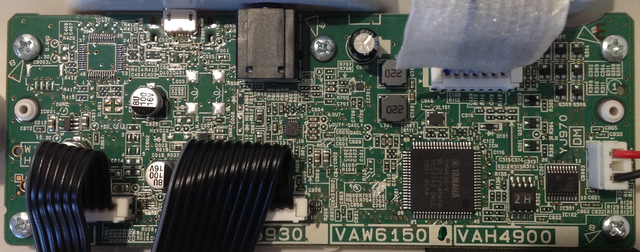
Even better, the A50 main board (DM) has a removable battery connector. If I rustle up a compatible cable and connectors, I can tap into existing battery power without soldering. I was already planning to use a short 3.5mm patch cable to jump the headphone OUT to the Dev Delay IN. Again, no soldering to SMT traces, etc. I like “reversible” mods!
I had enough headaches and scars from soldering mod chips to game console boards back in the day. 🙂
I hope this discussion provided some useful advice — no matter what you mod.
Copyright © 2021 Paul J. Drongowski