Now that Akai have introduced the new Akai MPK Mini Play Mk3, original first generation Mini Plays are going on sale. Being a notorious bottom-feeder (doing the most with the least), I cashed in a few loyalty points and bought one.
Sound On Sound magazine recently reviewed the new mk3. Many of their comments apply to the original MPK Mini Play; basic functionality has not changed. The mk3 includes an improved second generation MPK Mini keybed, a bigger and better speaker, a different panel layout and different, narrower pads. Everything else is pretty much the same. Having an OLED in an inexpensive product like the MPK Mini Play is a luxury.
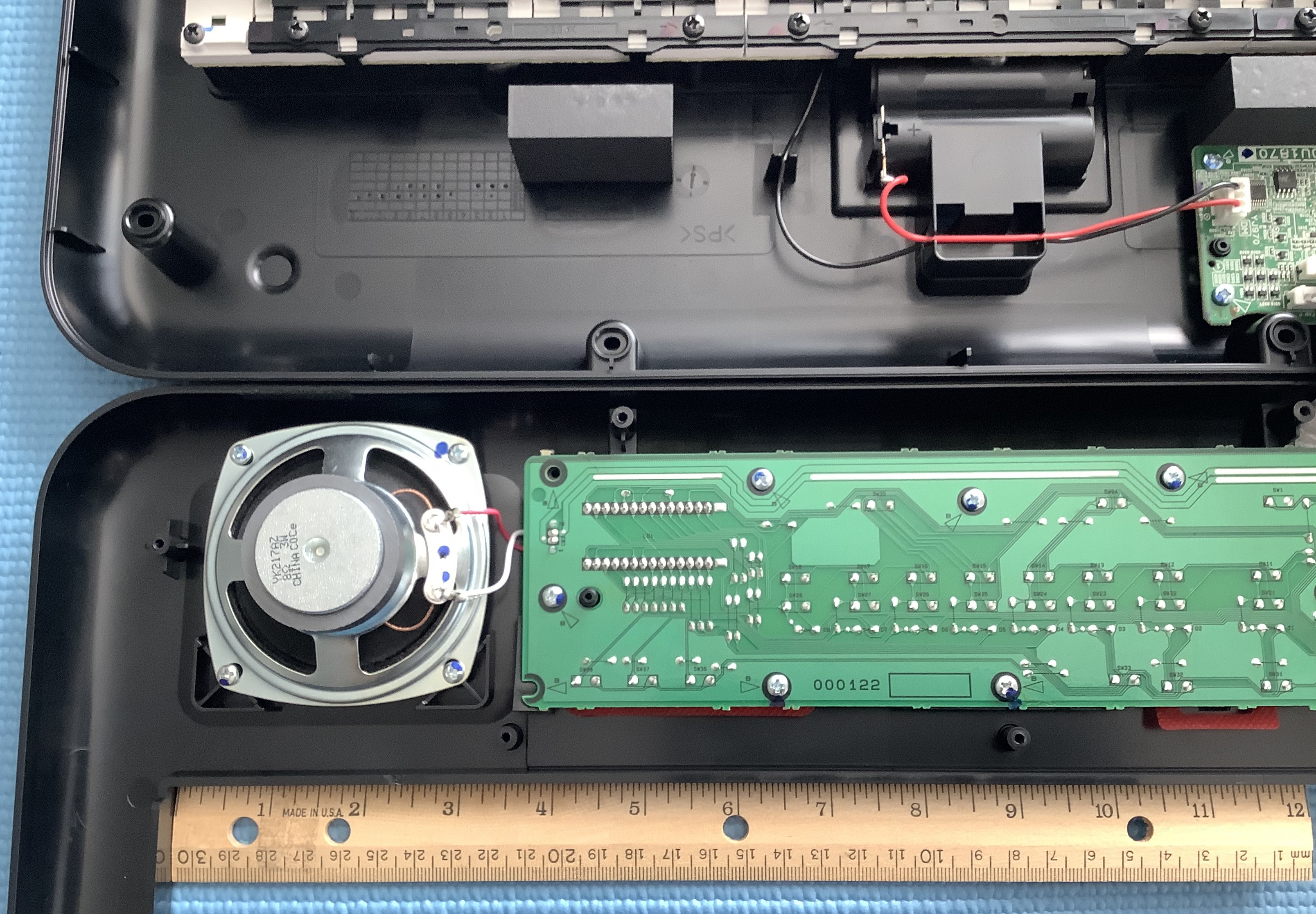
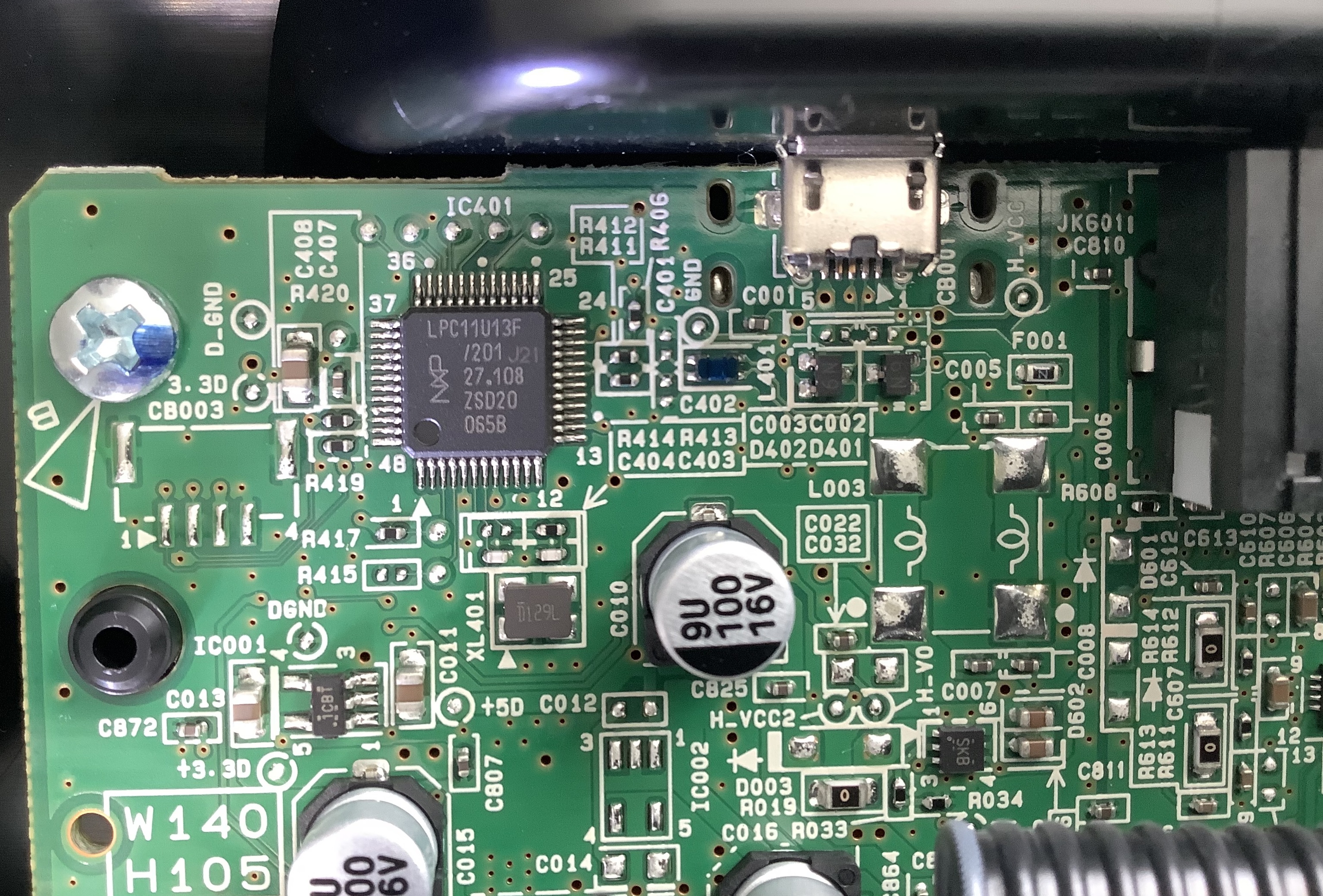
For the el cheapo price, the MPK Mini Play is surprisingly well-made. The keyboard and knobs don’t feel cheap although I doubt if they are very durable. All of the back connectors are mounted directly on the main printed circuit board (PCB) and should be treated with respect and care. There are numerous USB connector repair videos on-line (for the similar Akai MPK Mini), so beware when handling any of the Minis.
As to the Mk3 improvements, I get it. The original’s speaker is quite weak with limited frequency range. The original keybed is a little touchy. Keys need to be struck firmly to reliably trigger notes. One cannot play soft notes; forget nuance. The pads aren’t bad, however. Pads have always been Akai’s strong point.
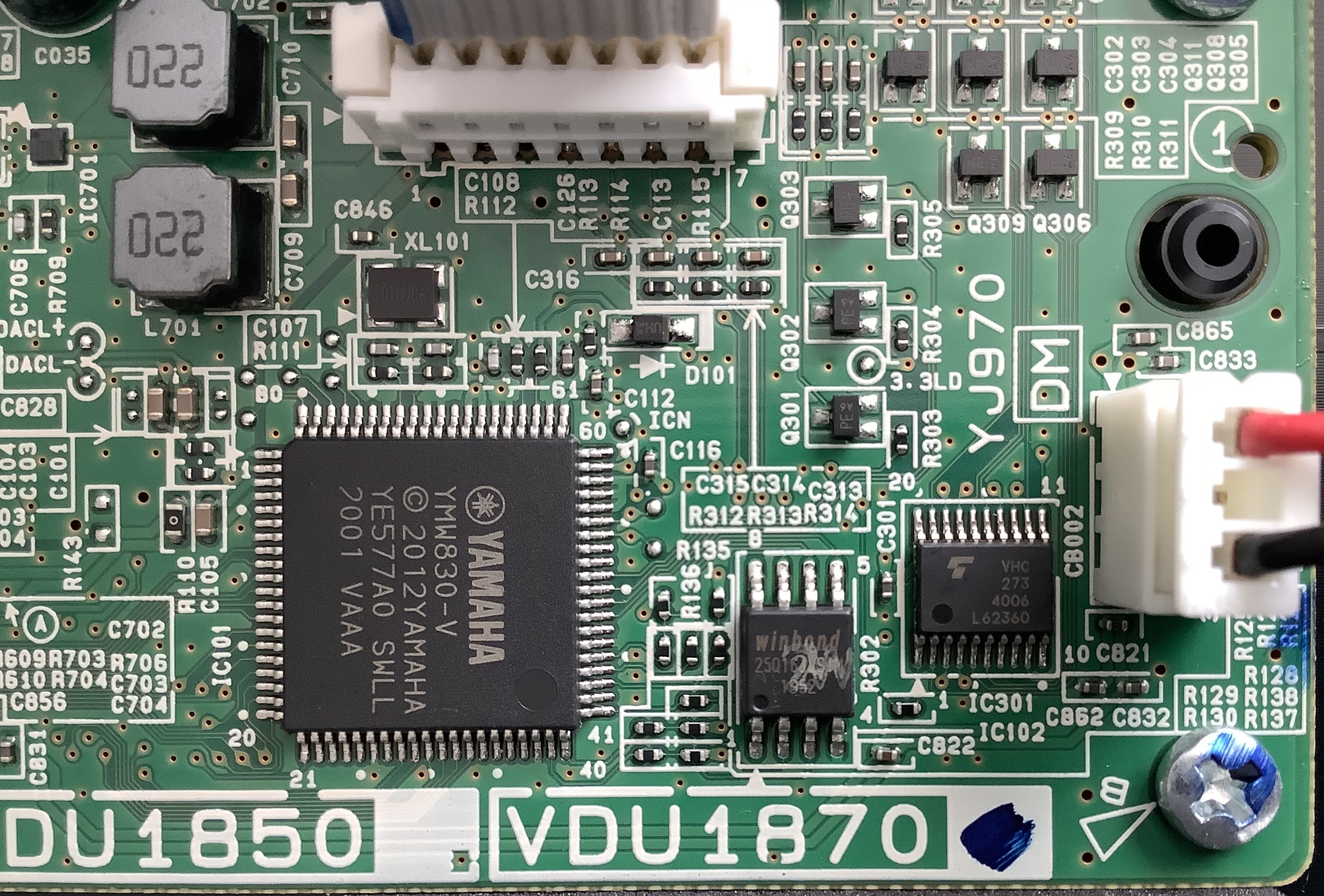
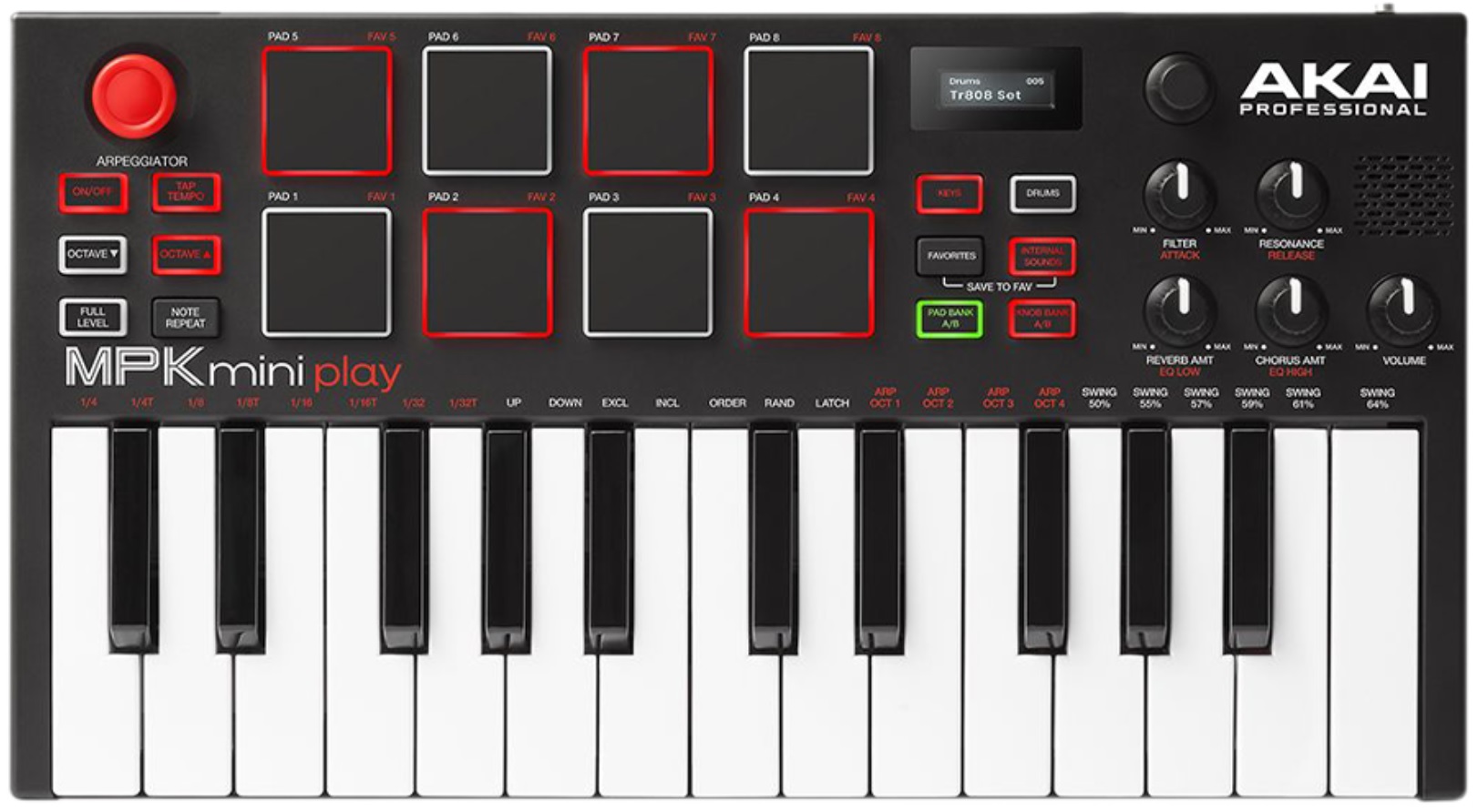
The sound engine is the Dream S.A.S. SAM2635 with its 8MByte CleanWave® soundset. The Mini Play’s soundset has 128 General MIDI sounds, 9 drum sets and one sound effects (SFX) set. By and large, it’s a decent sounding GM set including the reverb and chorus. The front panel knobs let you tweak filter cut-off, resonance, attack time, release time, reverb level, chorus level, EQ low and EQ high. Edits can be saved to one of eight Favorite locations. In this regard, the Mini Play is one-up on the Yamaha PSS-A50. (The PSS-A50 price is in the same neighborhood as the Mini Play.)
That’s the good news. Now the bad news. As mentioned in the Sound On Sound review, the incoming MIDI implementation is a nightmare. [I’m still figuring it out.] Foremost, the Akai Mini Play is not a multi-timbral GM module. The Akai software modifies (filters? blocks? mangles?) whatever MIDI you send to it before it sends its own internal MIDI stream to the SAM2635.
This is a shame and a lost opportunity for Akai and its customers. The Mini Play could be so much more if it allowed a direct path to the SAM2635. The Dream firmware is a complete GM/GS implementation. WTF, Akai? Akai would sell shed-loads more if the Mini Play was an actual GM module.
I’ve encountered Dream synthesis before in the Modern Device Fluxamasynth and the midiPlus miniEngine USB. Unlike the Akai, both devices suffer from noisy audio. I’m doubly disappointed because the Mini Play audio is relatively clean.
So, if you’re looking for a DAW-driven synth module, pass on both the original and Mk3.
As to the outgoing MIDI implementation — using the Mini Play as a controller — it is basic and functions well. The free software editor gives you access to everything configurable (pads, knobs and joystick), storing configurations into a Favorites slot. No complaints here although MPK Mini users might miss the four additional knobs provided by the plain ole Mini.
The Akai MPK Minis are the gateway drug to MPC production. Akai have always rolled out good value with their bundles. The Mini Play software bundle follows the path and includes:
- Akai VIP VST instrument and effect host environment
- AIR Hybrid 3 synthesizer
- Wobble synthesizer
- MPC Essentials (AKA tons of samples)
- ProTools | First
And, of course, Akai’s free MPC Beats application. Download and installation, if you go for everything, is laborious due to partnership arrangements and different authorization and licensing procedures.
Bottomline. A MIDI module it is not. If you want a tiny, inexpensive MIDI controller with a limited in-built synthesizer and a serious stack of content, give it a go. If you expect to play live, go for the Mk3 and the better keybed and speaker.
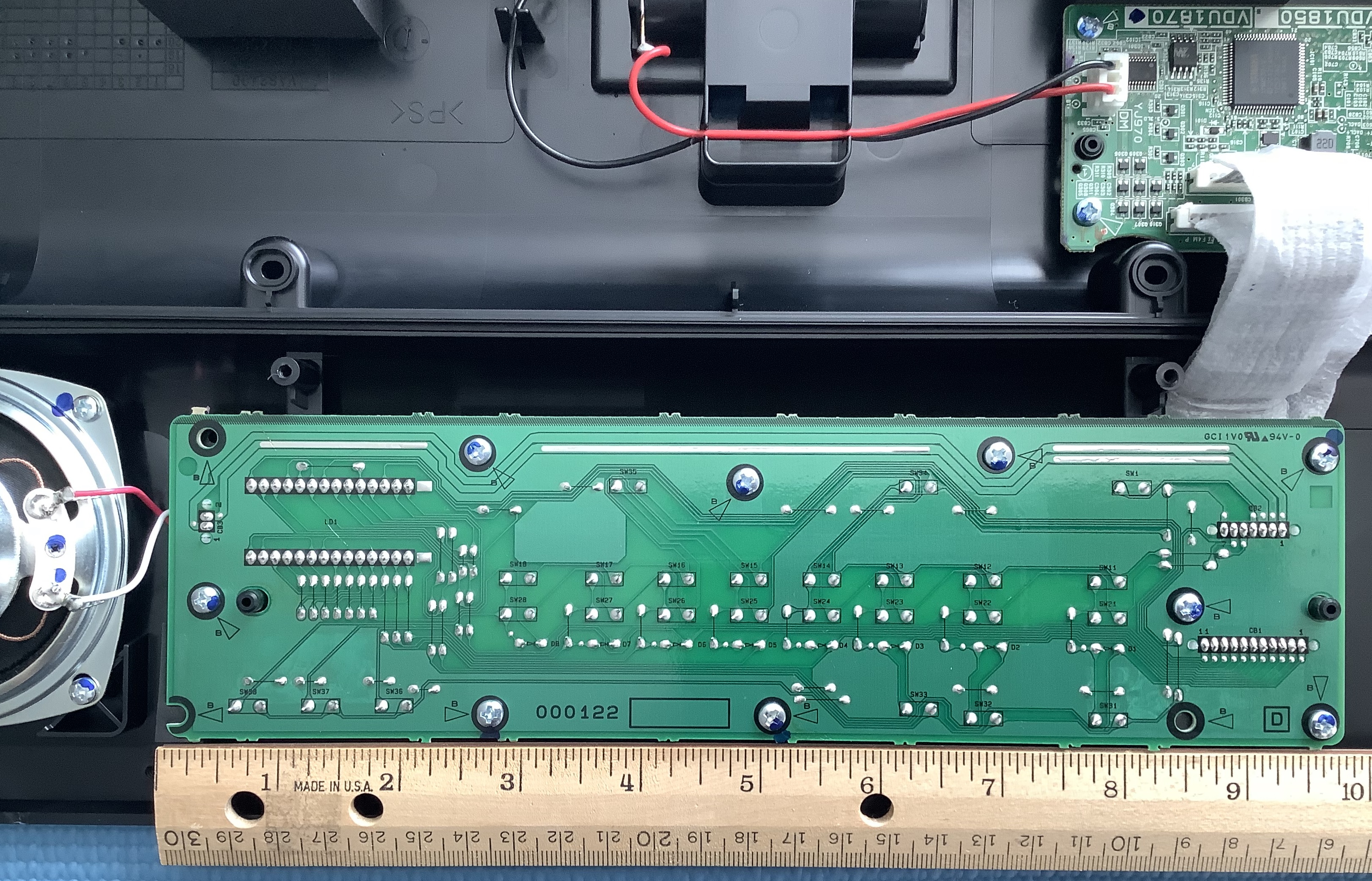
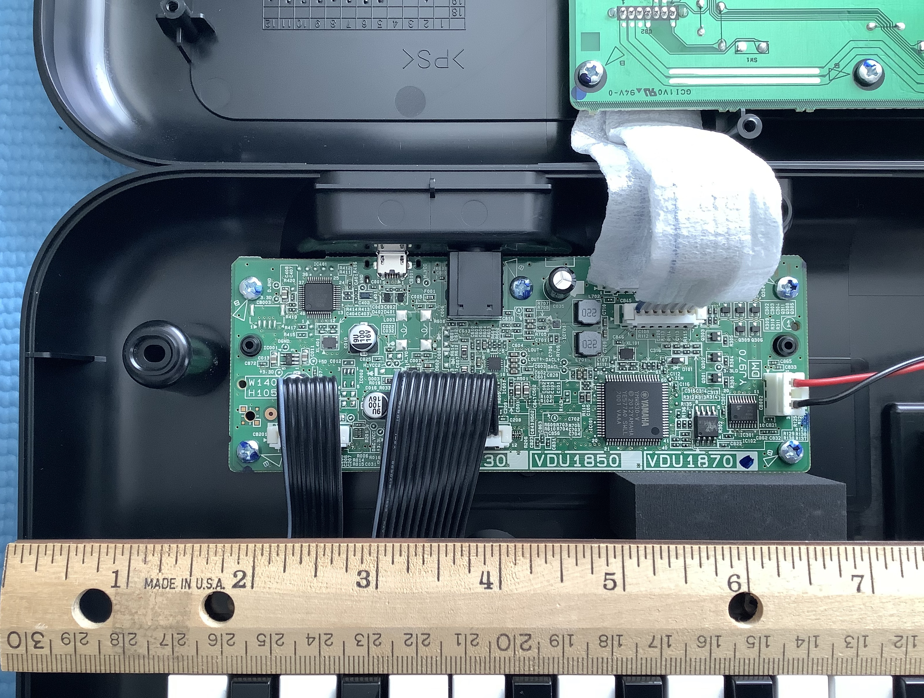
After initial disappointment about the MIDI implementation, I took a screwdriver to the MPK Mini Play. Naturally, a device this small and inexpensive is mod fodder. I will discuss mod potential in a future post.
Update: If you intend to use the Akai MPK Mini Play as a MIDI module, you must read my analysis of its MIDI implementation. If you want to mod the MPK Mini Play, start here and here.
Like the review? Check out the teardown (disassembly) and mods:
- Akai MPK Mini Play teardown (a look inside)
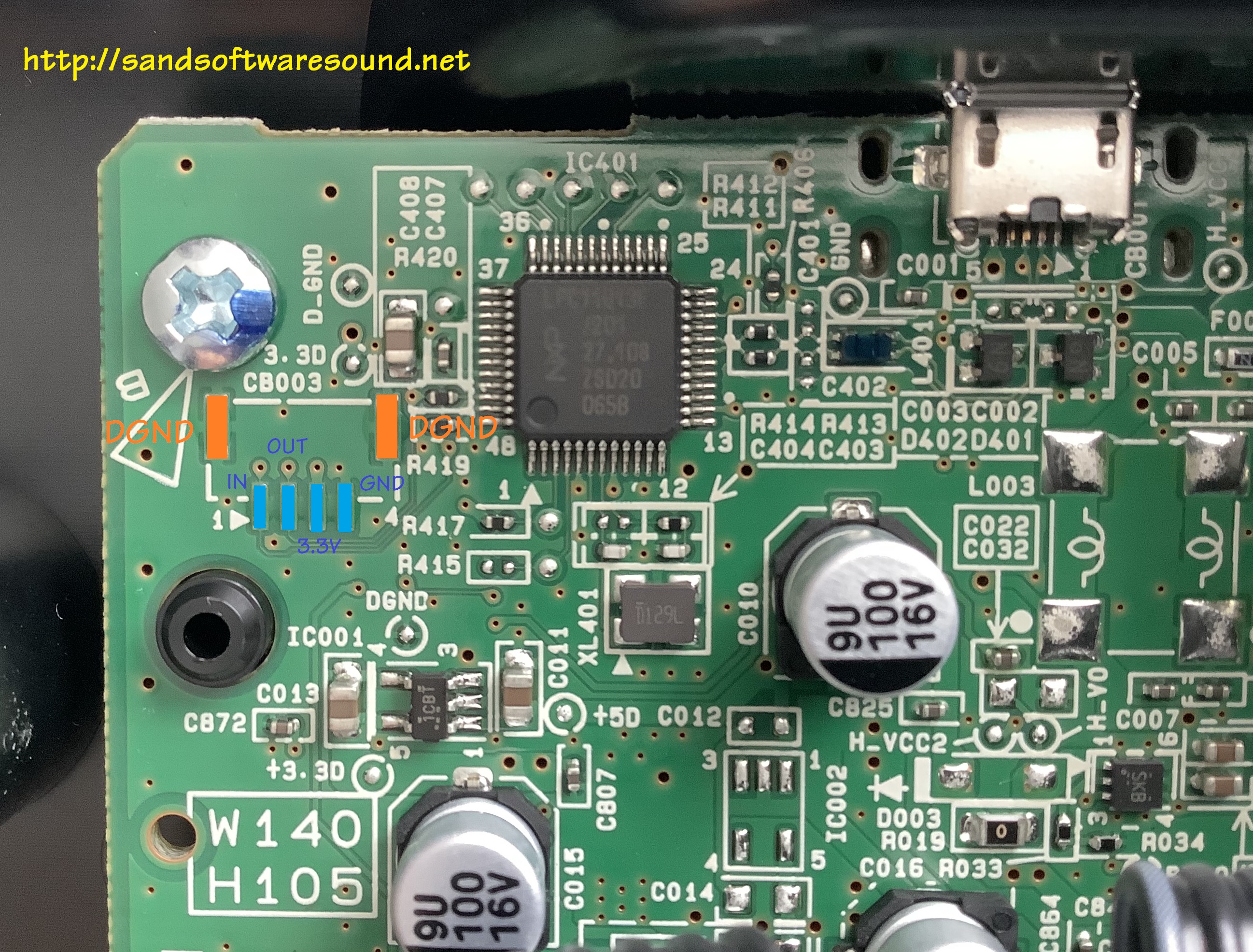
- Bring out the MPK Mini Play signals
- Monitor internal MPK Mini Play MIDI messages
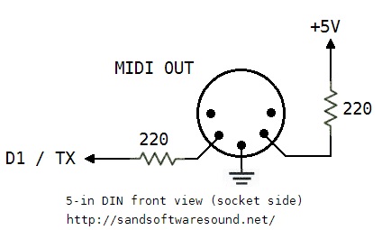
- Jam with Akai MPK Mini Play 5-pin MIDI IN and MIDI OUT
- Communicate with Akai MPK Mini Play MIDI over USB
Copyright © 2022 Paul J. Drongowski