After investigating a wireless iPad-based rig for church gigs, I decided to take a 180 and try wired! The urge was inspired by a recent thread in the MusicPlayer Keyboard Forum about taming the rat’s nest of wires that engulf our keyboard set-ups.
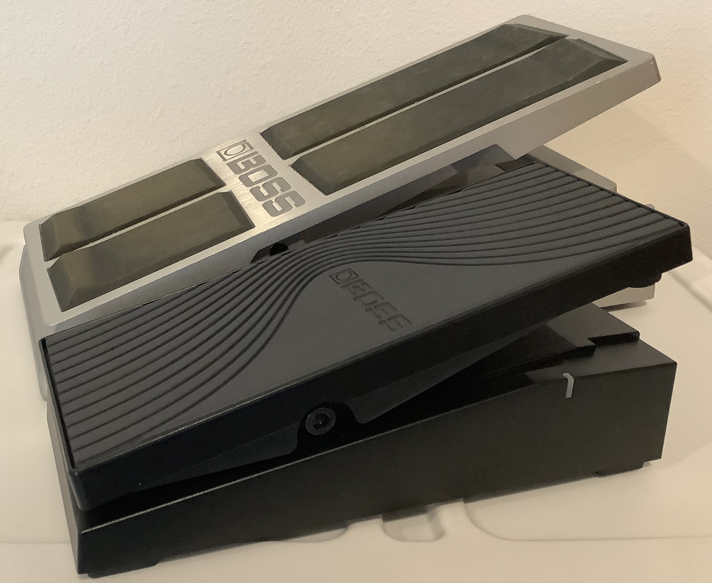
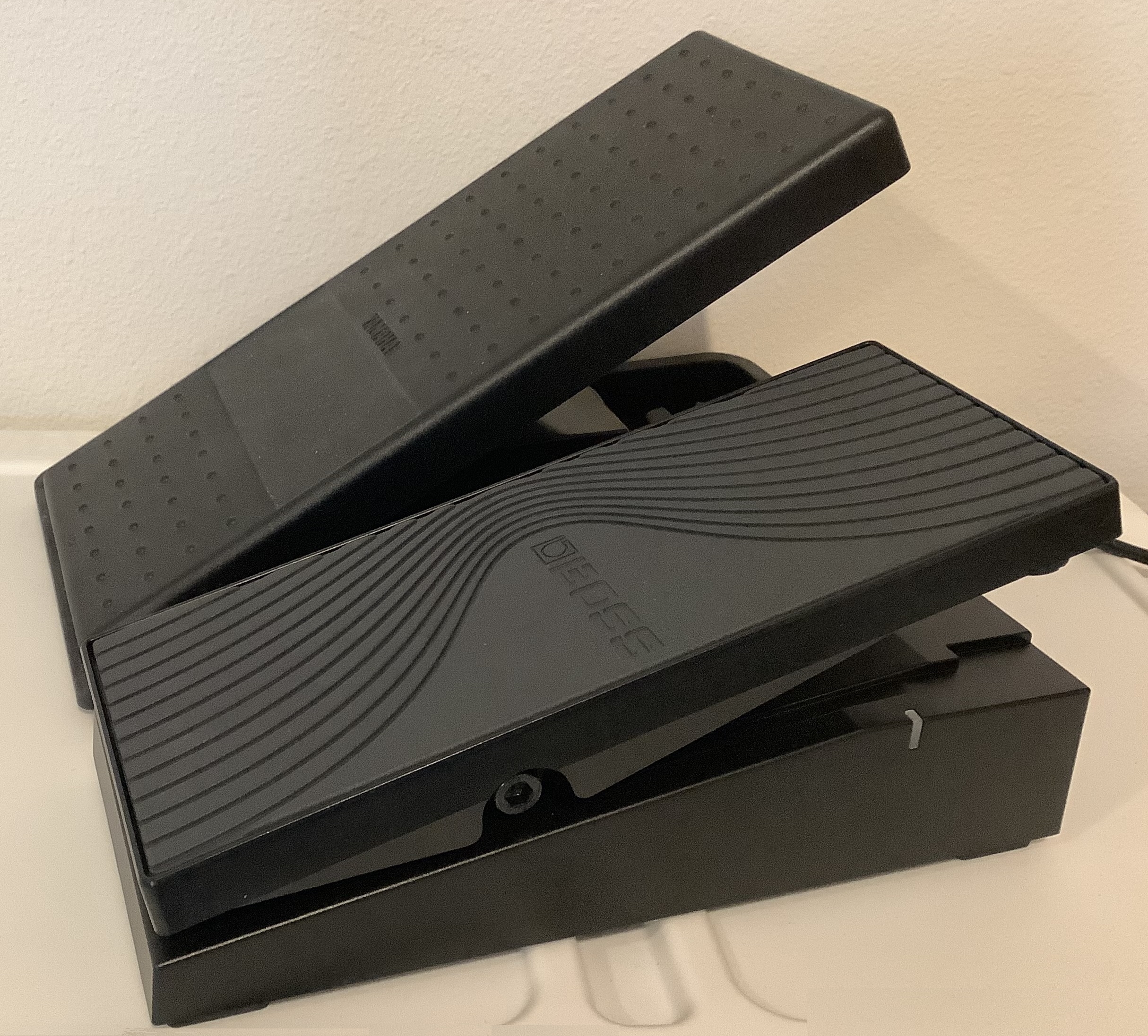
My approach goes all-in with MIDI over USB. Both the Korg Microkey Air 49 and the Boss EV-1-WL wireless MIDI expression pedal have full-size USB-B device ports, so it made sense to start with them and build out.
I really detest the iPad 3.5mm audio jack on my 3rd generation iPad Air. That may sound like crazy-talk to people owning phones and iPads without a 3.5mm audio jack. However, the jack’s placement exposes an inserted 3.5mm plug to all sorts of physical and sonic abuse. Every time I pick up or move the iPad, the jarred plug causes all manner of crackles, pops and hum — at loud volume, no less.
Thus, an external USB audio interface is a necessity. I pulled out an old Behringer UCA222 2-in/2-out USB audio interface, which was my PC audio workhorse for many years. (Now replaced by a Yamaha AG-06 mixing console and audio interface). The UCA222 is not the best interface, but it’s inexpensive. Sweetwater is selling these for about $10USD and you can’t go wrong at that price.
Based on my success with UCA222, I put a Creative Labs Sound Blaster Play 3 external USB sound adapter on order ($20USD). The Play 3 is even smaller and will do 24-bit, 96kHz given driver and control panel support. The Play 3 is not spec’ed as IOS compatible, but folks are having success with Play 3 and iPad.
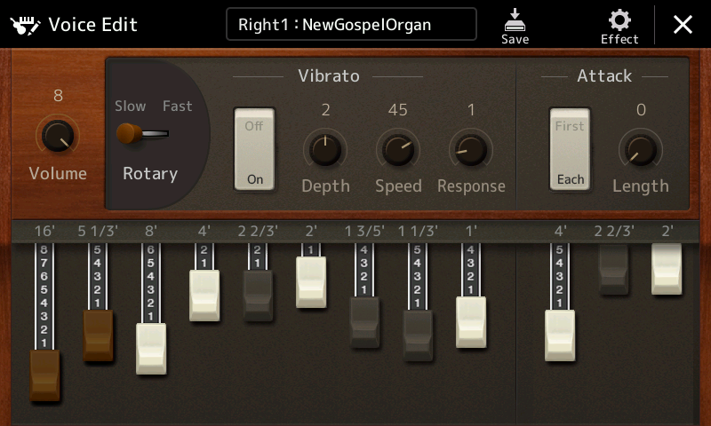
For extra credit, I would eventually like to control IK Multimedia B-3X with a Crumar D9U DIY drawbar controller. The D9U hasn’t seen much action lately and it would be good to get it into the mix. The D9U can do MIDI over USB through its micro USB port. That particular test must await another rainy (snowy?) day as I need to adapt the D9U Arduino sketch for B-3X.
Well, if you were counting, that’s four (4) MIDI devices. The Apple Lightning to USB 3 Camera Adapter has only one USB-A host port. Uh, oh. We need a hub. Fortunately, I have a few Sabrent HB-MCRM 4-port portable USB 2.0 hubs on hand. The Sabrent HB-MCRM is small, light and cheap (less than $10USD).
One could use an olde style Apple USB Camera Adapter, but why put yourself through the agony? Better to have the Lightning charge/power port than fight electrical current restrictions. BTW, I wish the Belkin RockStar™ had three ports: USB-A host, Lightning charge and 3.5mm audio.
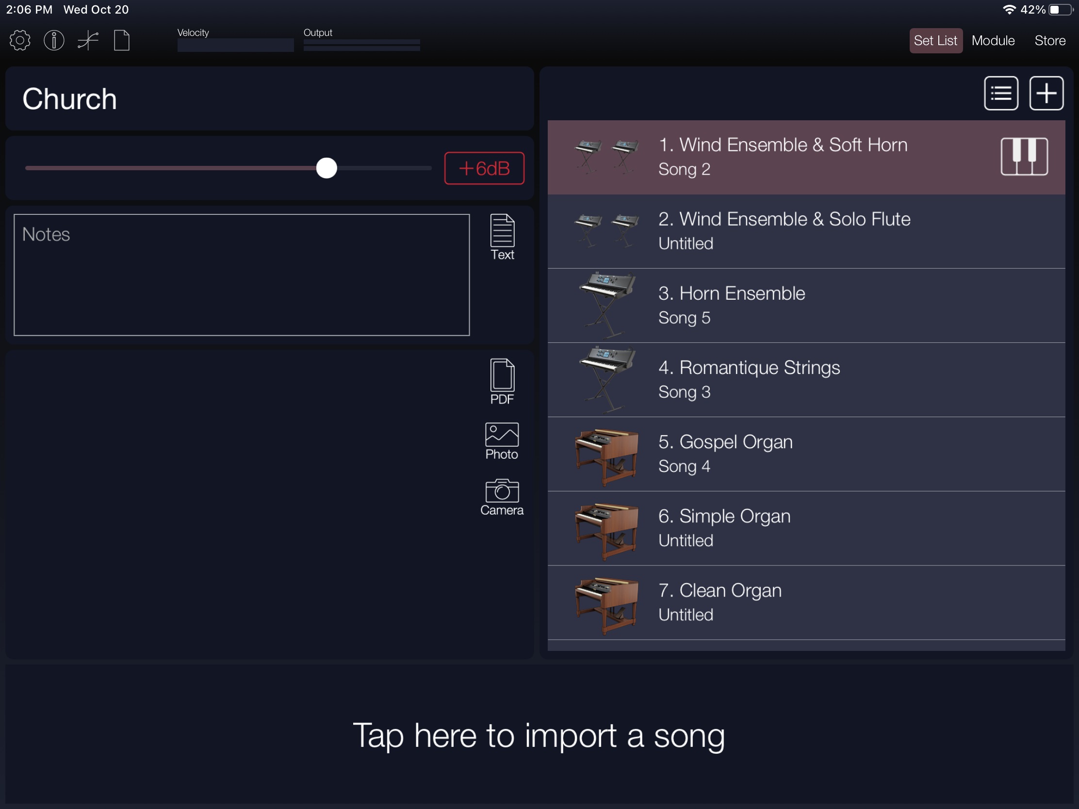
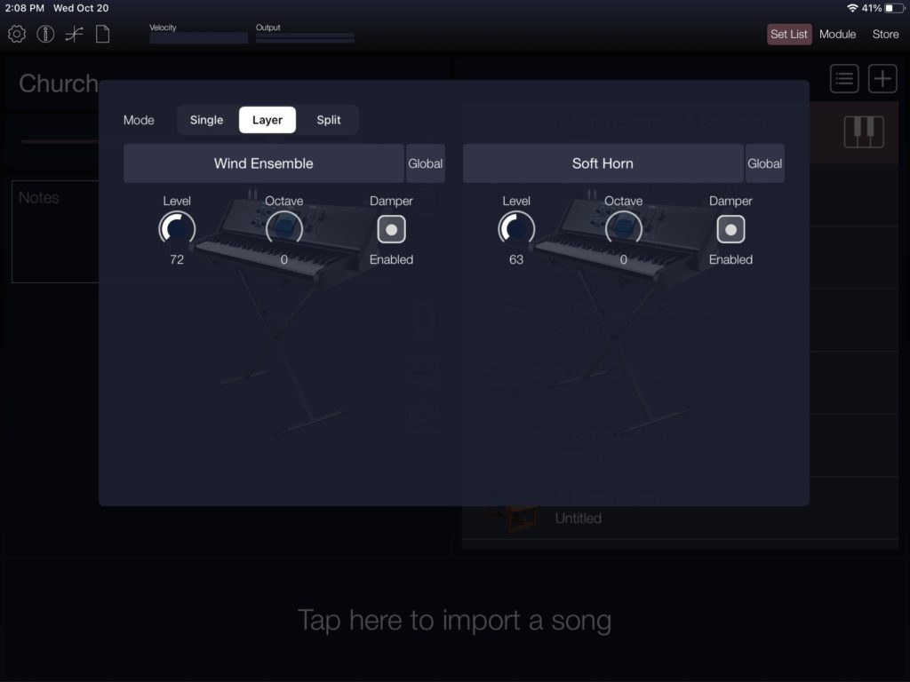
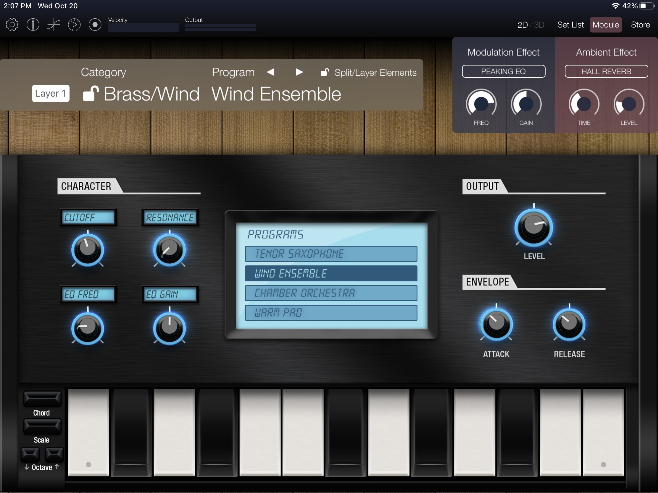
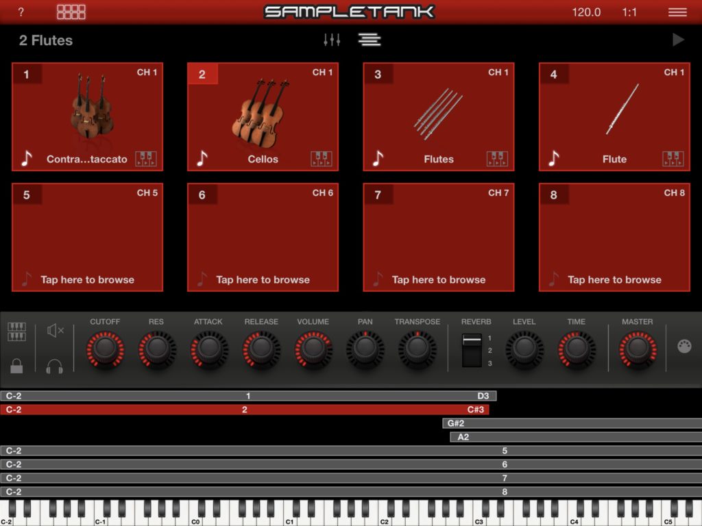
It’s not rocket science, so plug it all in and success! Core MIDI merges the MIDI input streams together. Korg Module Pro and Crudebyte iSymphonic Orchestra respond to the Microkey Air and the Boss EV-1-WL expression pedal. I expect the D9U to function correctly, too, if I get its sketch right.
                                 S   <---->  Microkey Air 49
                                 a
                   Apple         b H <---->  EV-1-WL expression pedal
  iPad Air <---->   USB   <----> r u
                  Adapter        e b <---->  UCA222 audio
                                 n
                                 t   <---->  D9U drawbars
As to power, the EV-1-WL is not bus-powered. It needs either an external power adapter (9V 500mA center negative) or two AA batteries. The Korg Microkey Air and the Behringer UCA222 draw power from the Apple adapter through the Sabrent hub. (The Sabrent hub itself is not a powered hub, keeping things simple.)
A Lightning extension cable connects the Apple adapter to the iPad. This means only one cable to the iPad. The Lightning connector is reliably tight and eliminates the pops and crackles when moving the iPad. Most of the cabling sits on the floor out-of-sight.
As to audio connection, there are two options. Option 1 is running a long-ish unbalanced analog cable to the monitor. (The monitor is a Behringer B205D with a balanced XLR OUT to front-of-house.) Option 2 adds a USB extension cable between the hub and the audio interface (UCA222) for most of the distance with a short unbalanced cable from the interface to the monitor. Option 2 keeps things digital as long as possible, eliminating hum and other noise problems due to a long unbalanced cable run. Of course, there are limitations to USB extension (USB 2.0: 5M, USB 3.0: 3M).
Well, there you have it — an inexpensive, super-light, wired iPad rig. I haven’t found Bluetooth MIDI latency to be a problem, but wired latency should be less, if that is your concern. The USB approach seems to be less fiddly as to pairing, merging, etc.
If you’re curious about my wireless MIDI adventures, check out:
- Wire Less: Part 1, Korg Microkey Air 49
- Wire Less: Part 2, Belkin RockStar™
- Wire Less: Part 3, Boss EV-1-WL wireless MIDI expression pedal
More blasts from the past about the Crumar D9U:
- Day 1: D9U Assembly
- Day 2: Assembly and D9U test sketch
- Day 3: D9U debugging
- Day 4: D9U MIDI testing
- Day 5: D9U sketch for Nord Electro 2
The Crumar D9U works pretty well with the Yamaha Reface YC, too.
Copyright © 2021 Paul J. Drongowski