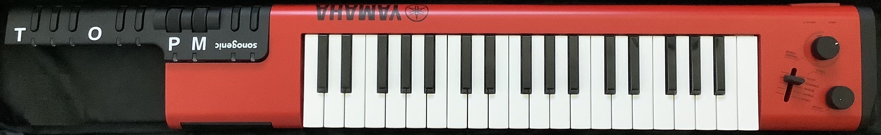
I’d like to add more animation to the distinctly sound of the Yamaha PSS-A50. I really like the Korg Volca Mix stereo width effect and want to add something similar as either a mod or an external effect.
My intuition suggests the Haas effect or as Wikipedia would have it, the precedence effect. This well-known effect delays one side of a stereo pair that changes our perception of a sound source in the stereo field.
Rather than buying — and potentially, disassembling — a delay effect pedal, I decided to give the Synthrotek Dev Delay kit a try. Synthrotek offer a broad range of inexpensive kits and heck, they’re located nearby in the Pacific Northwest!
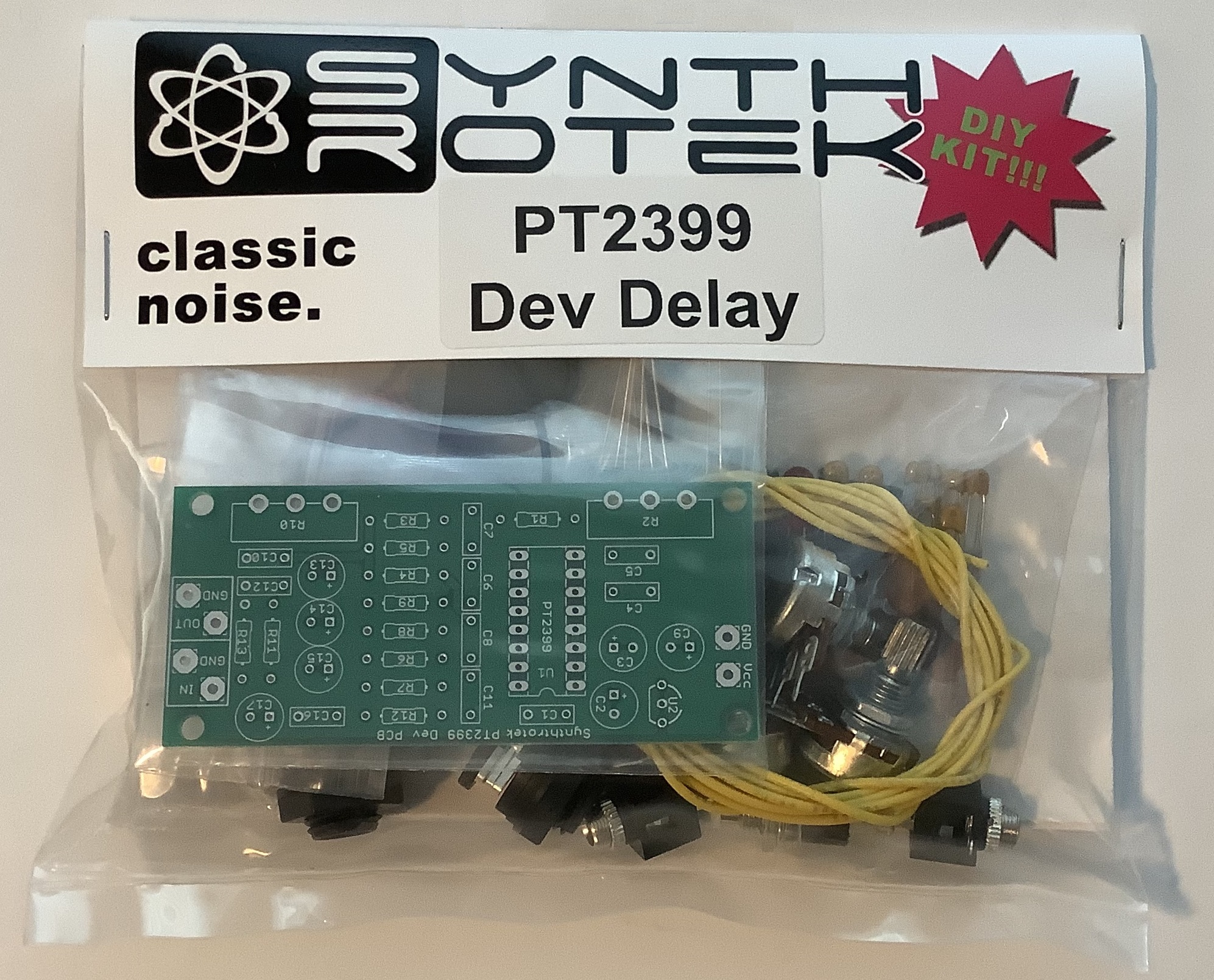
The kit is a relatively straightforward implementation of a PT2399 delay — right off the datasheet. The Princeton Technology PT2399 is a workhorse appearing in many guitar pedals, synth modules, karaoke mixers, etc. The VCO control voltage (pin 6) determines the delay time and is set by a 50K linear potentiometer. The delayed signal is fed back into the input with feedback level set by a second 50K linear potentiometer. In addition to the PT2399 and its discrete minions (resistors and capacitors), there is an LM78L05 +5V power regulator.
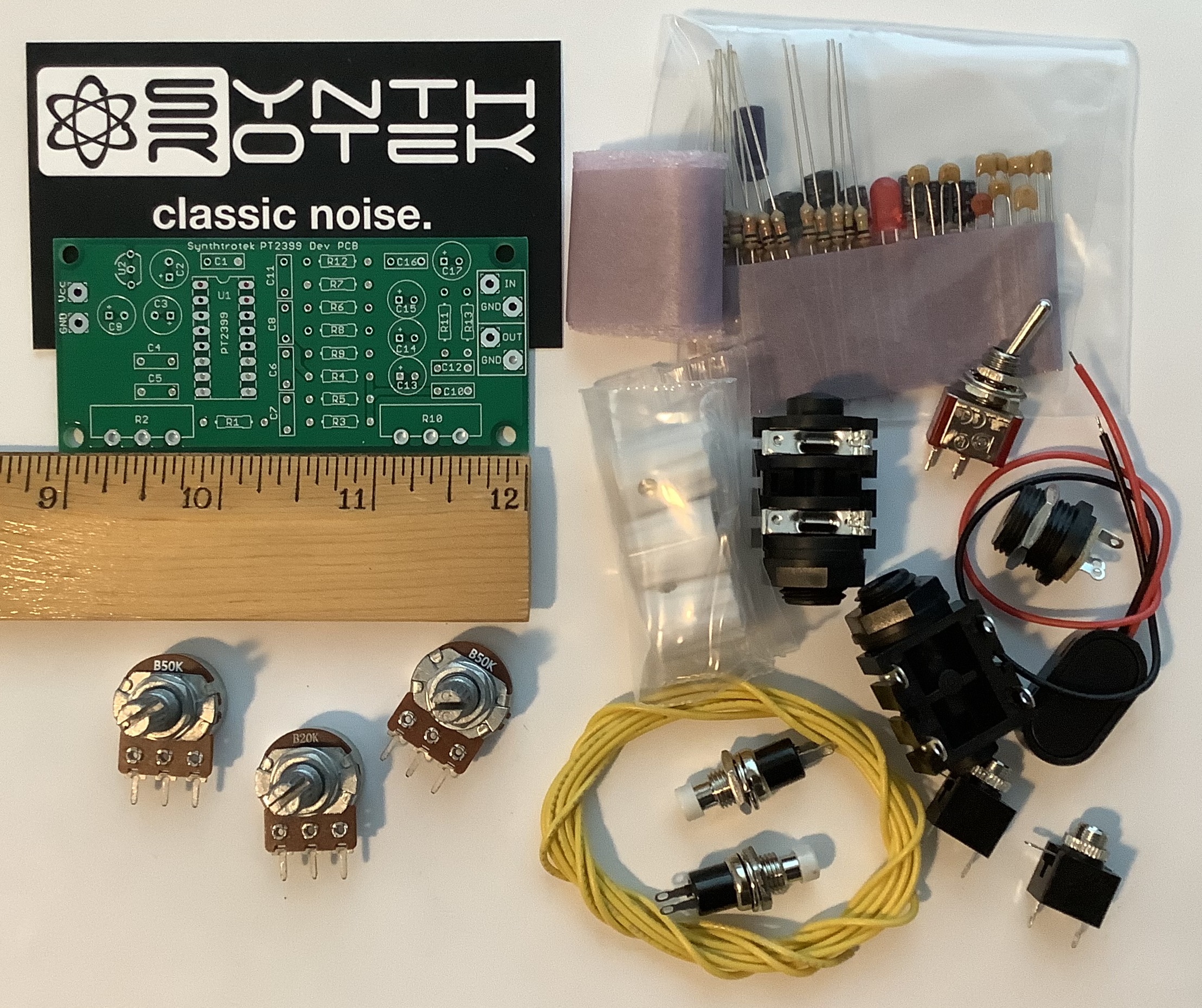
Synthrotek provide a rather nice board and kit of parts. It includes many unexpected extras: both 3.5mm and 1/4″ phone jacks, knobs, switches, power LED and parts needed for PT2399 mods. Quite decent of them! My only niggle is the quality of the potentiometers. Physically, they appear dingy and functionally they are a little noisy. I would call them “surplus grade.” If building the finished kit into a permanent project like a pedal, I would replace the pots with fresher parts. Please don’t let this concern stop you from buying a kit, however.
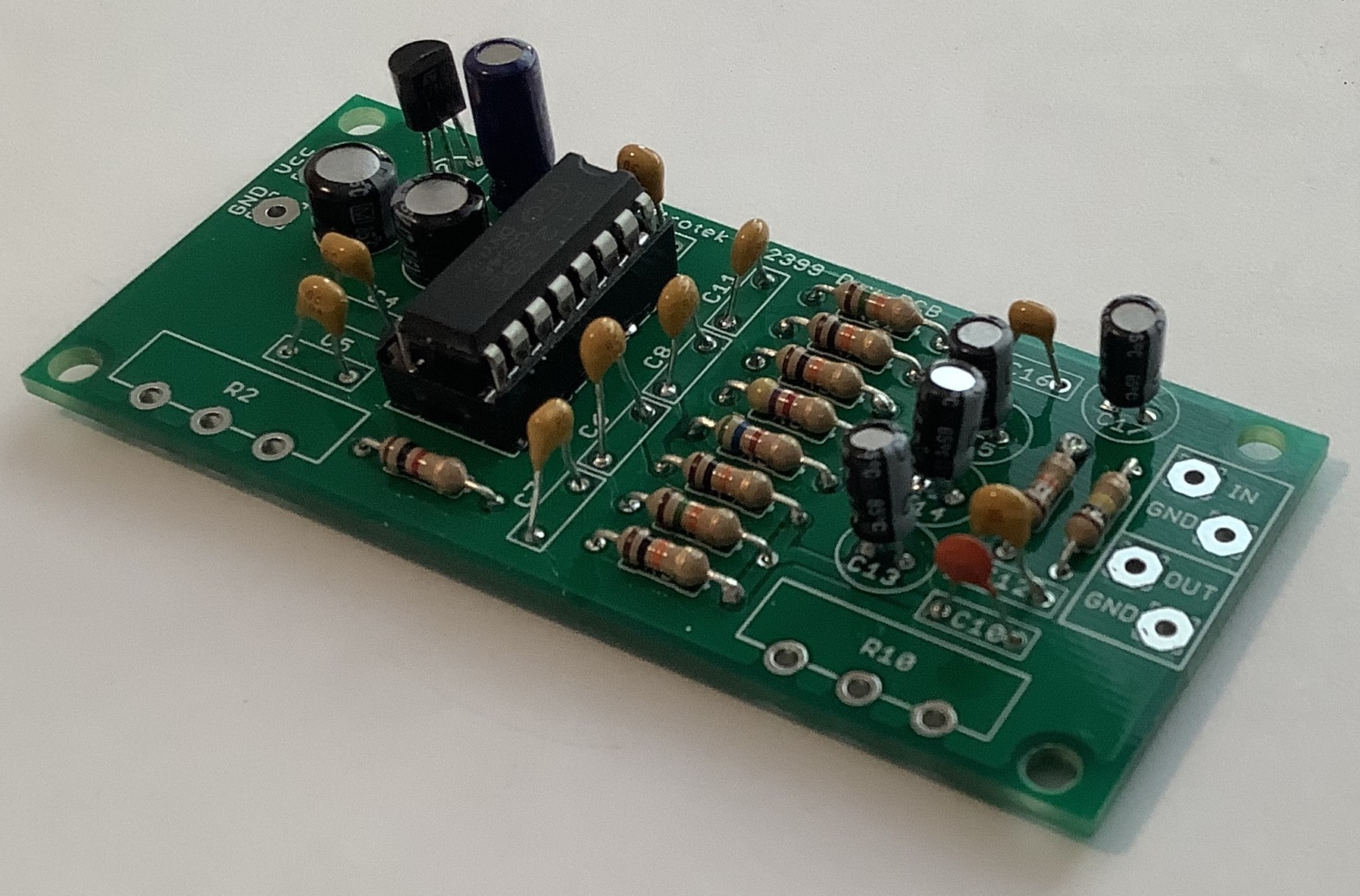
The kit builds quickly enough. For some crazy reason, I had trouble keeping my soldering tip clean. Once I got some flux from Lowes (desperation!), soldering went better. Maybe it’s my eyes, but even the DIP and standard size discretes seem smaller and smaller…
I like reconfigurable builds that are easily re-purposed. So, I added a number of embellishments. I added two three-contact terminal blocks (5mm pitch) for the pots on the PCB. The terminals match up with the potentiometers’ leads and since the pots are linear, I flipped them around and connected them to the terminal blocks directly. I don’t think you can play this trick with log pots, by the way.
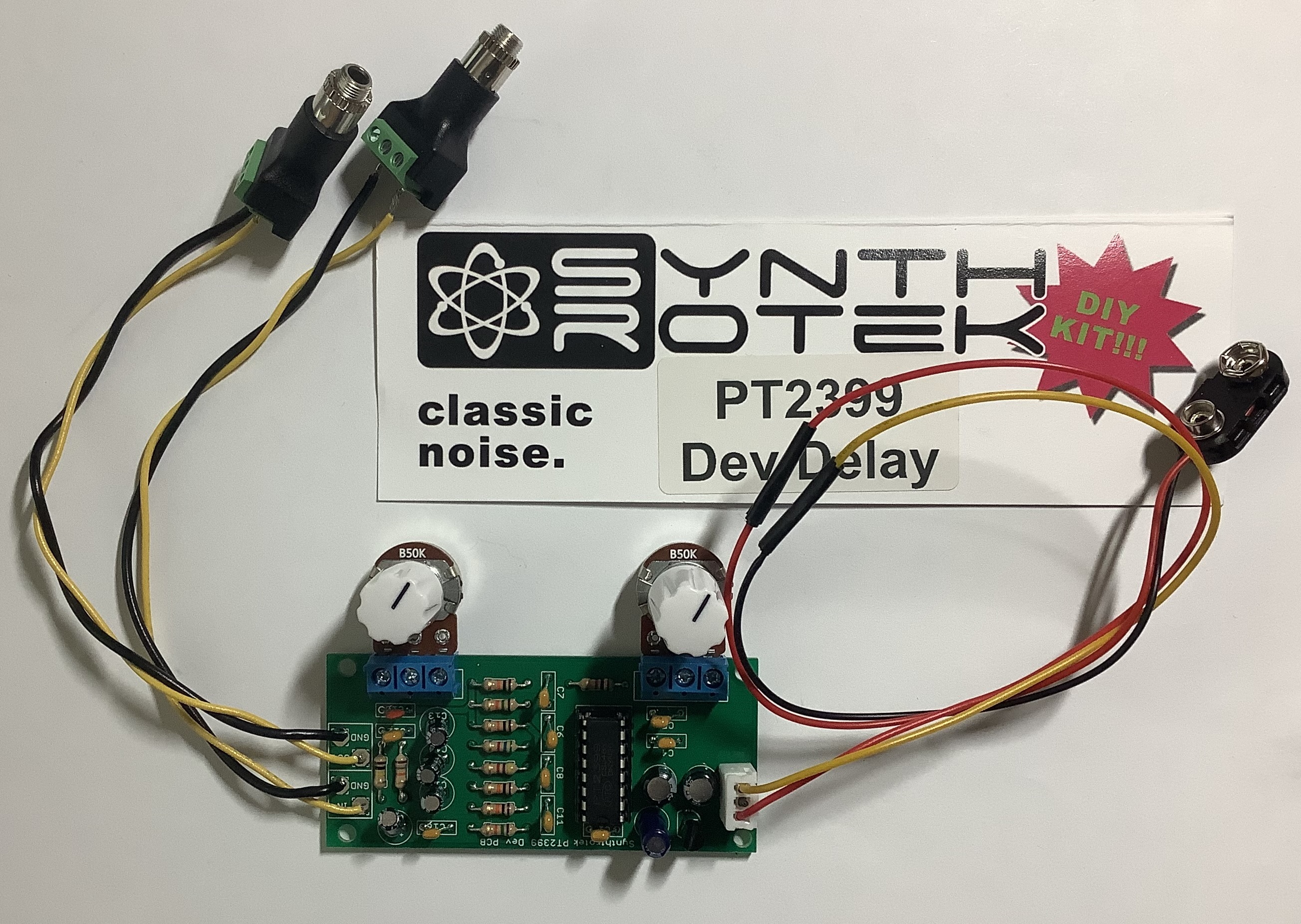
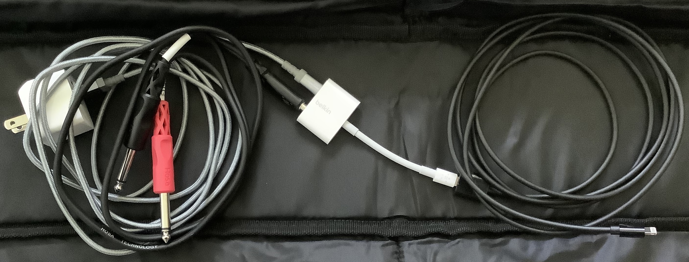
I added a JST connector for battery connections. Audio in and out wires are soldered directly to the PCB. The other end of the audio wires are connected to 3.5mm jacks with in-built terminal blocks for ring, tip and sleeve. These audio jacks are very handy and I intend to use more of them in the future. They have a shaft and nut for panel mounting, making them suitable for permanent installation, not just prototying.
Connect a battery…
… and nothing.
This is the moment which we builders all dread.
Drag out the digital multi-meter (DMM). Power is good to the board. Audio wires are good to the board. Crank up the volume on the powered speaker and a faint signal is heard.
So, what’s up? Check the connections to the audio jacks and, holy smokes! Instead of signal to tip (T) and ground to sleeve (S), I have ground to ring (R). I didn’t pay close enough attention to the terminal order and labels.
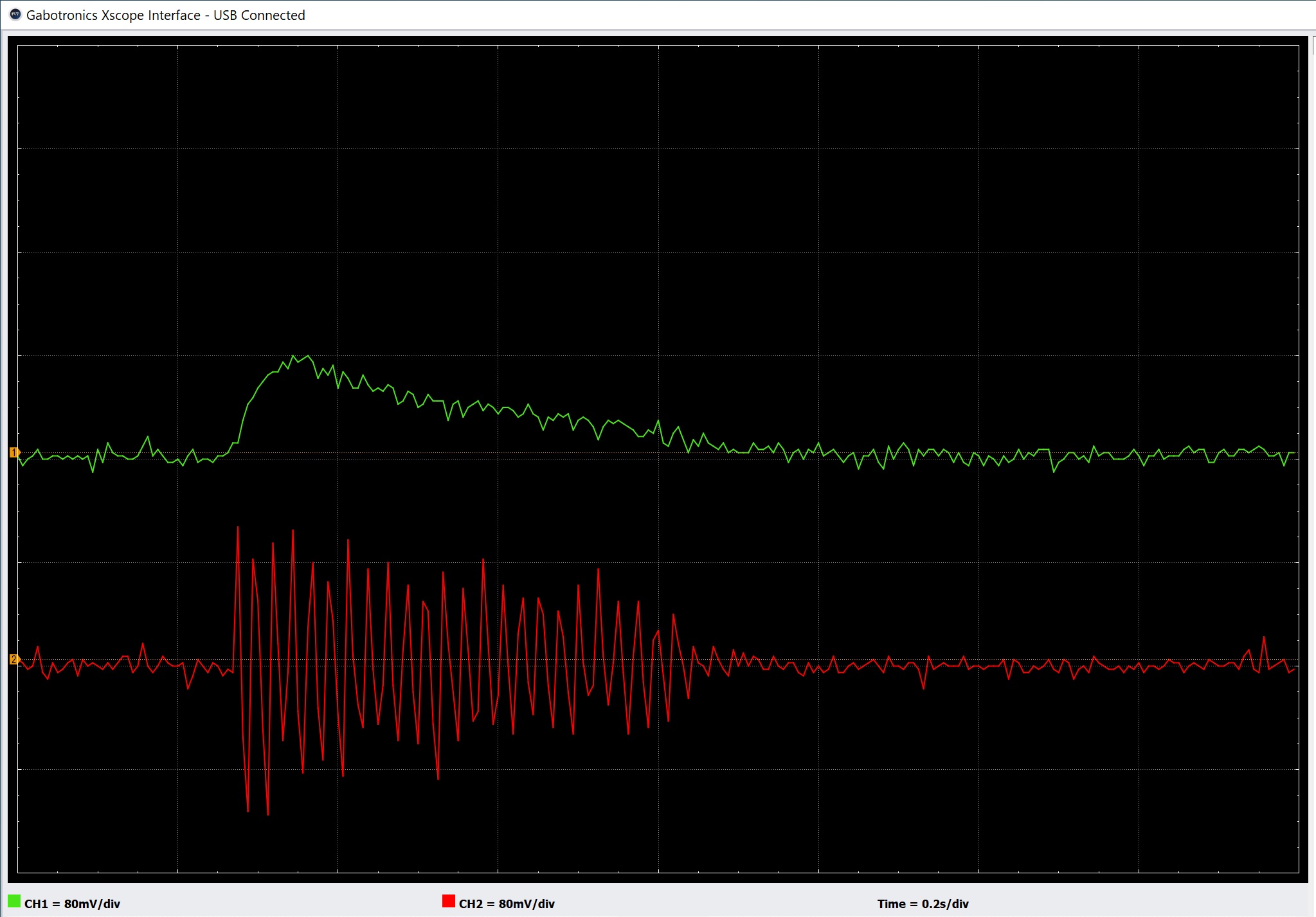
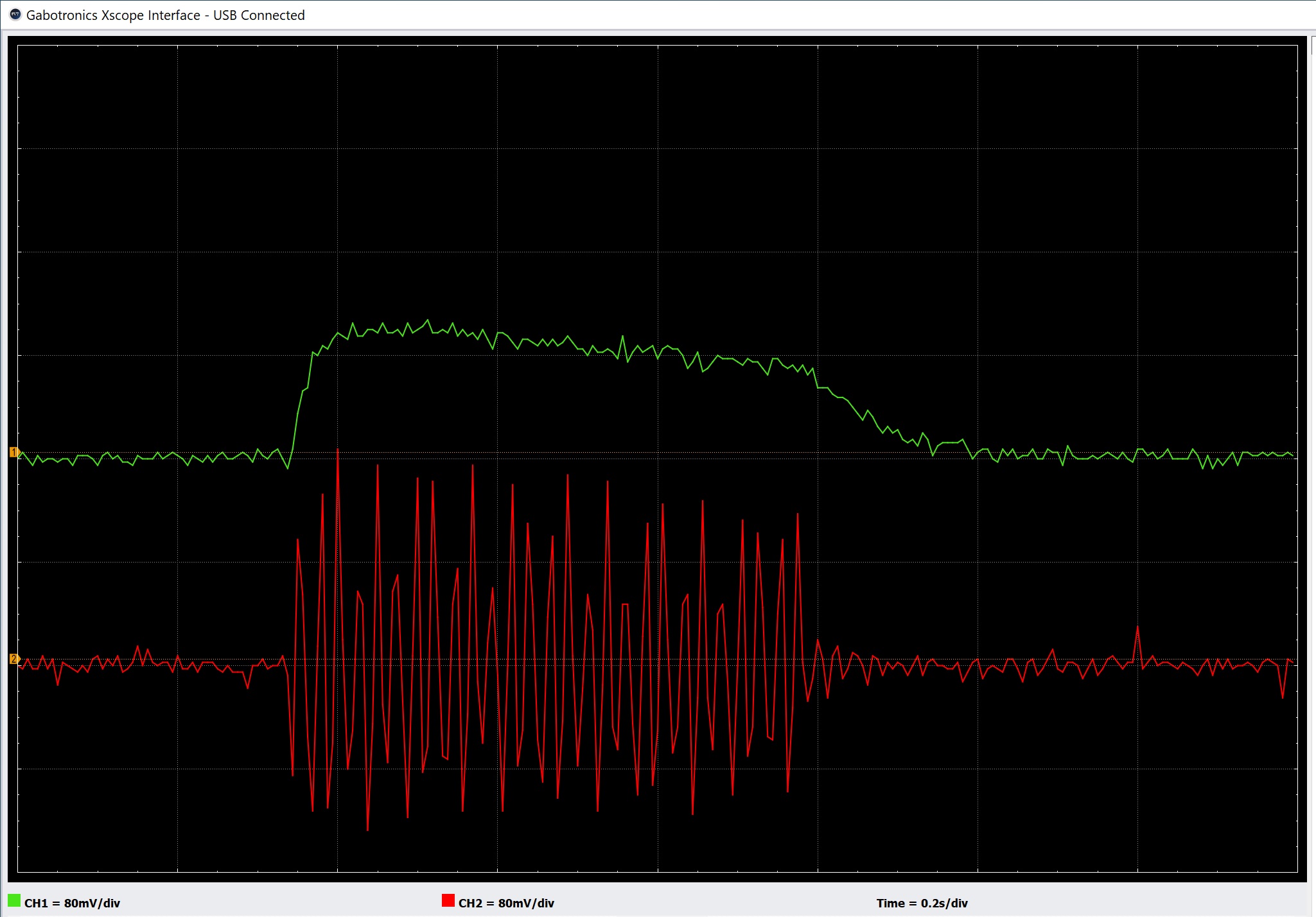
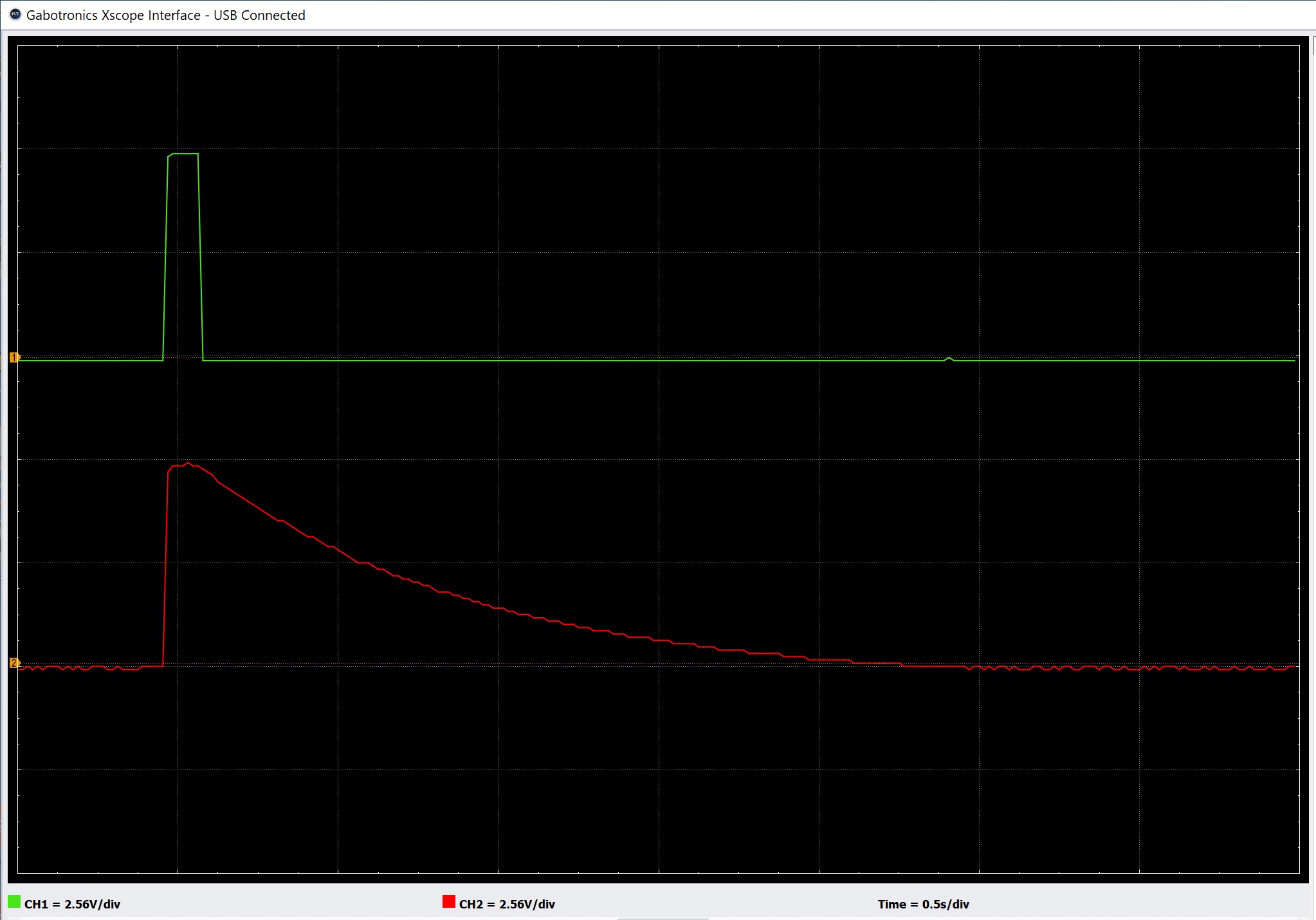
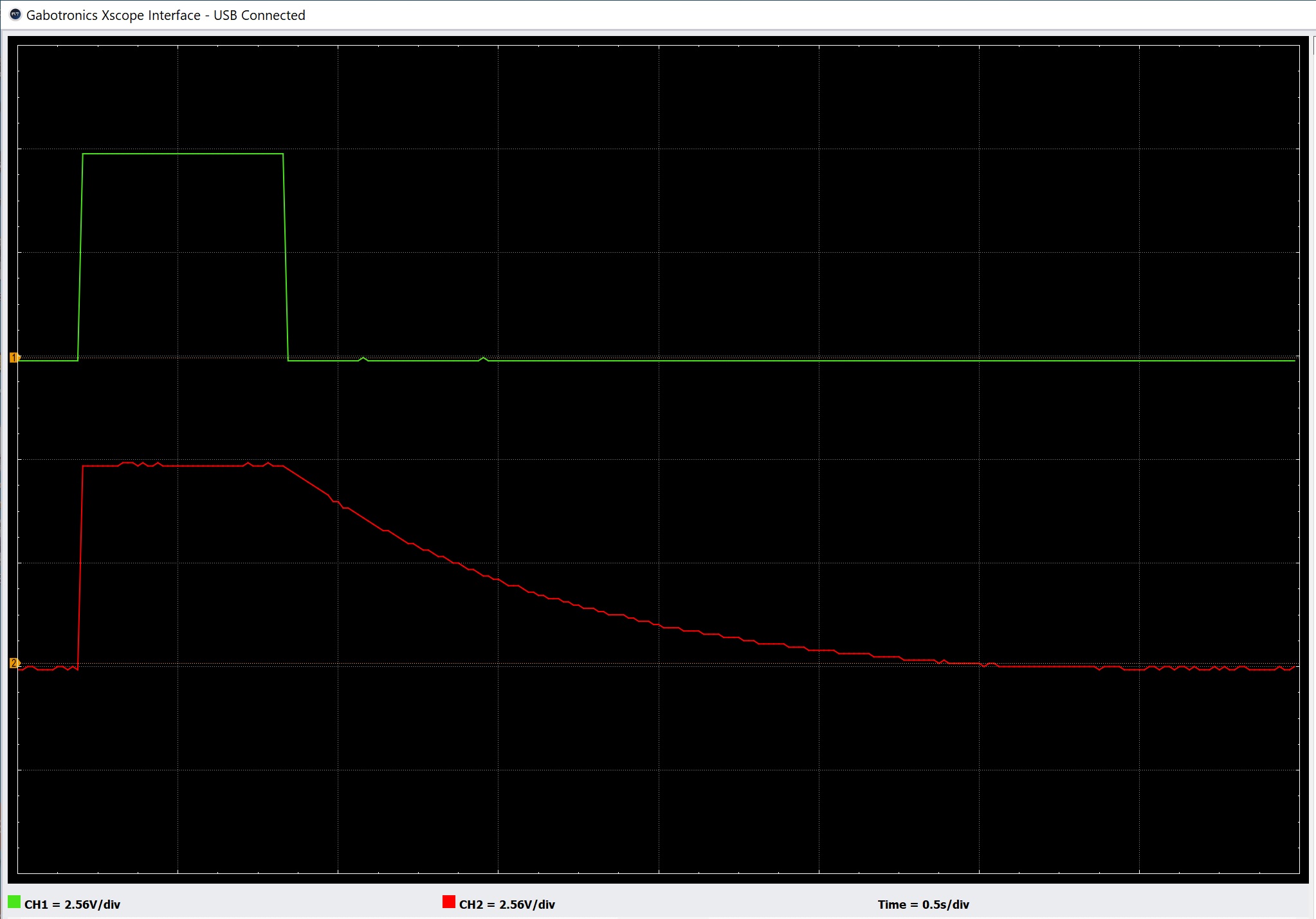
After a quick fix, the Dev Delay was up and running. I used the PSS-A50 as my signal source and had it play a drum pattern over and over. Yes, you can get King Tubby with this unit!
My experiments with the Haas effect, however, were less exciting — too subtle for my taste. I noticed that the Korg Volca Mix does not use an analog or digital delay circuit. Thus, my search for a stereo animator goes on. I have a Thai Kits (Future Kit) FK651 stereo simulator in hand and will try it next.
As to the Synthrotek Dev Delay kit, if you need a digital delay in kit form, give it a go! Great for audio innovators.
Copyright © 2021 Paul J. Drongowski