
I performed a few more quick experiments over the weekend and I’m happy to report further success!
Although the Akai MPK Mini Play has an internal Dream S.A.S. SAM2635 synthezier chip, the Akai microcontroller software blocks full access — a true shame because the SAM2635 firmware is a complete General MIDI/GS implementation.
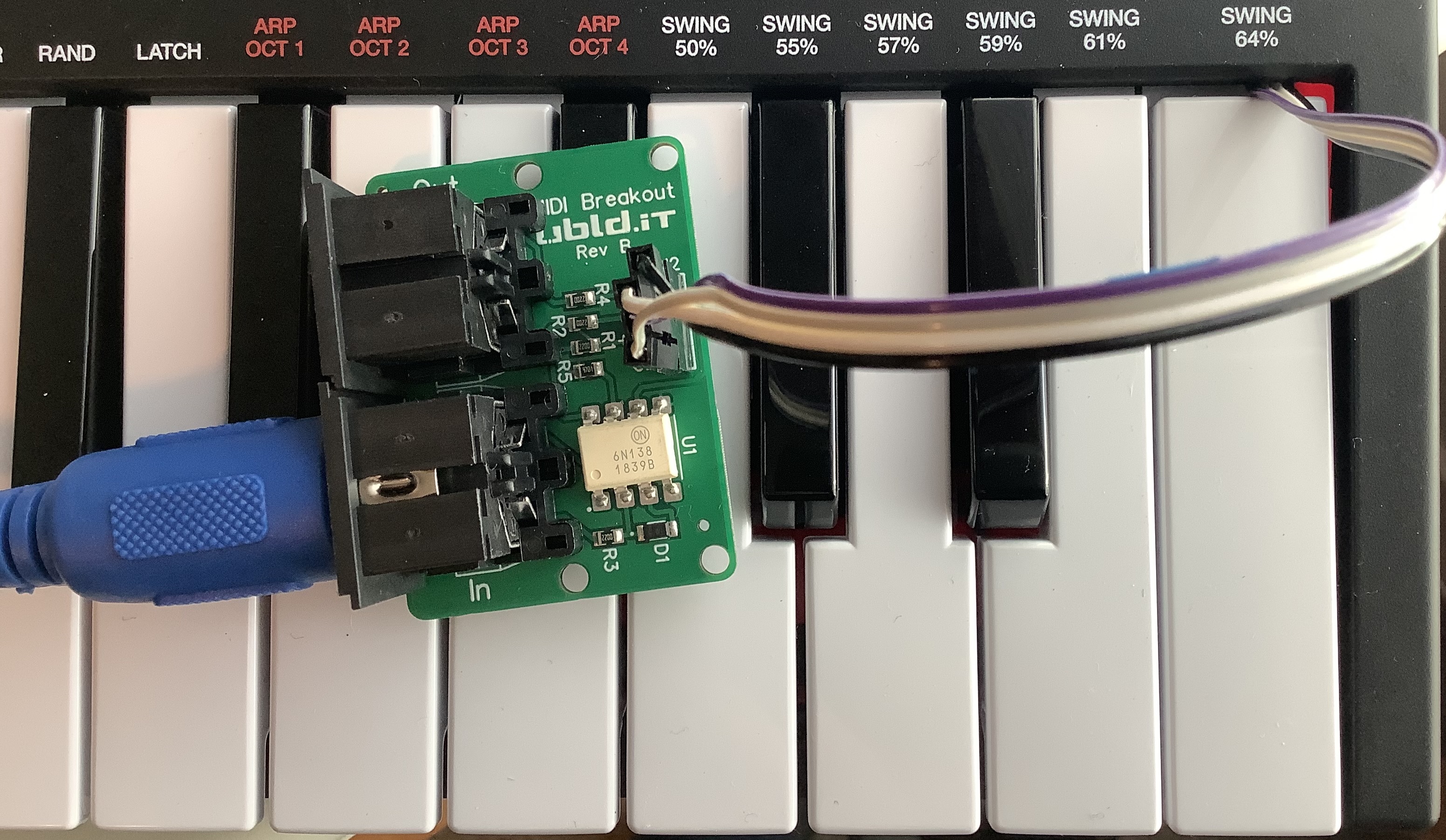
I modified an Akai MPK Mini Play bringing out four signals from the main printed circuit board (PCB):
- MIDI IN white wire: SAM2635_RX MIDI input
- MIDI OUT black wire: SAM2635_TX MIDI output
- Ground grey wire: Ground for external power
- +3.3V purple wire: +3.3V for external power
My goal is to override the Arm microcontroller and drive the SAM2635 over 5-pin MIDI, completely bypassing the Akai software. If successful, we should be able to use the fully functionality afforded by the SAM2635.
Test 1: UBLD.IT MIDI breakout board
A full test of the UBLD.IT MIDI breakout board is in order before testing the MPK Mini Play. If the UBLD.IT isn’t working, any test with the Mini Play will fail, too.
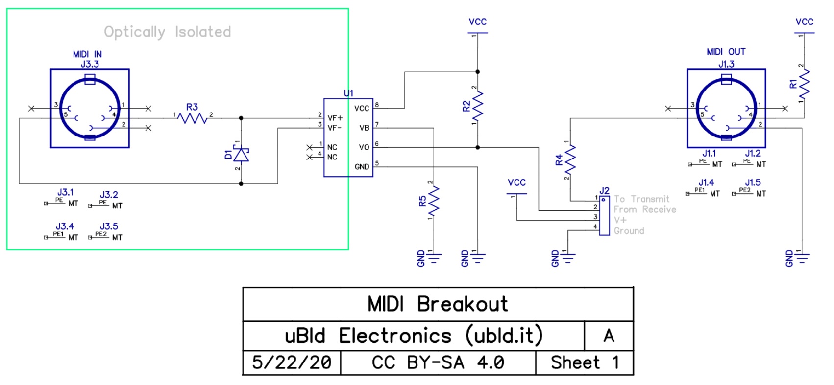
The UBLD.IT board is a really nice, small MIDI IN and MIDI OUT breakout board. The MIDI OUT side is dirt simple and sends the transmit signal (pin 1 of J2) to the 5-pin DIN connector through a current limiting resistor (R4). Please recall that MIDI is an active LOW current loop. The return pin — the other side of the current loop — is connected to VCC (the positive voltage rail) through a current limiting resistor (R1).
The MIDI IN side provides the opto-isolated MIDI logic signal to the receiving electronics. DIN pins 4 and 5 send the incoming current through the LED in the opto-isolator (U1). The opto-isolator is a 6N138. The LED shines on a photo-transistor. The photo-transistor is essentially a light-controlled pull-down path from the positive voltage rail to ground. Thus, the MIDI logic signal is HIGH when idling and is active LOW. The incoming logic signal is sent off the board through the receive pin (pin 2 of J2).
The test set-up is simple. Jumper the transmit and receive pins (J2). Connect +3.3V and Ground using the Mini Play as a power source. Connect UBLD.IT MIDI IN to the MIDI OUT of any handy keyboard like a Yamaha MODX. Connect UBLD.IT MIDI OUT to the MIDI IN of a second keyboard like a Yamaha Genos. Turn on the Mini Play to apply power to the interface. Play the sending keyboard (MODX) and listen for sounds produced by the receiving keyboard (Genos).
It was gratifying to hear the Genos while playing MODX, i.e., the UBLD.IT is working correctly.
Test 2: Play using an external keyboard
The next test is to drive the Akai MPK Mini Play itself.
Here’s the test set-up. Leave the MODX connected to UBLD.IT MIDI IN. Disconnect UBLD.IT MIDI OUT since we don’t need it. Connect the UBLD.IT pins (J2) to the corresponding Mini Play signals. Receive is SAM2695_RX (white wire) and transmit is SAM2695_TX (black wire). Leave ground and +3.3V connected (grey and purple wires, respectively).
Turn on the Akai MPK Mini Play. Play the MODX. You should hear sounds produced by the SAM2635. Yay! 🙂 Try the MODX MOD and pitch bend wheels.
I believe this design works electronically because MIDI is active LOW and idles in the HIGH state. The pull-down transistor in the opto-isolator pulls the SAM2635_RX node LOW. Normally, you cannot tie two logic outputs together, but the pull-down works in this situation. (Think “wire OR”.) By the way, you shouldn’t play the Mini Play keys or turn its knobs as MIDI signals from the Arm microcontroller will interfere with the MIDI IN logic signal! I recommend turning INTERNAL SOUNDS off when using the 5-pin MIDI IN.
The next step is to try the Dream SAM2635 as a GM/GS synthesizer. Stay tuned.
Copyright © 2022 Paul J. Drongowski