I’m still kicking around ideas for small, ultra-low cost MIDI tone modules. Random thoughts to follow…
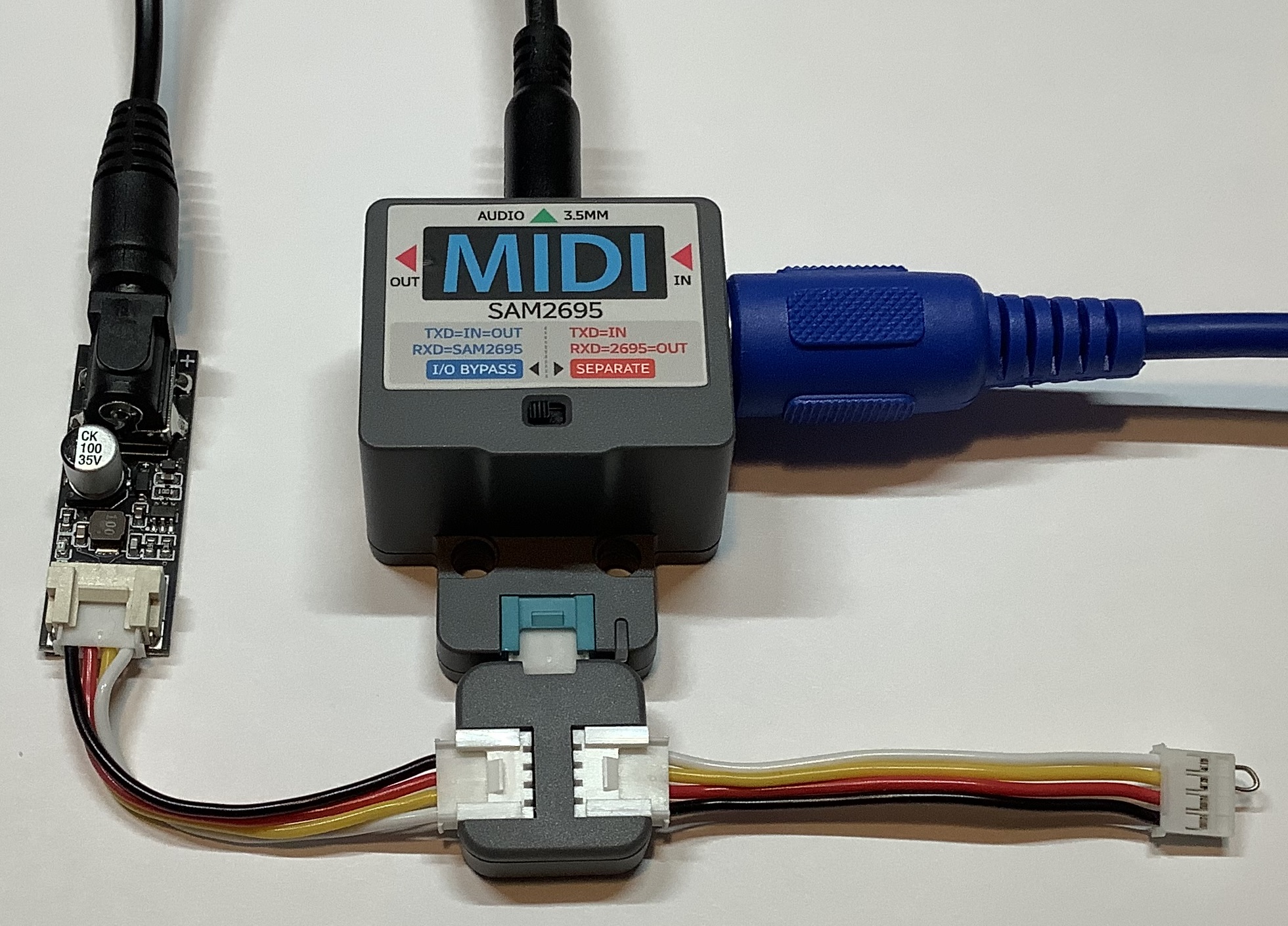
I completed the SAM2695 project using the M5Stack U187 MIDI module. Using a nibbling tool and utility knife, I cut a few holes along the edge of a Hammond 1591CSBK plastic project box. I packed the MIDI module and cabling into the Hammond box and strung cables through the holes. There are three cables:
- An in-line barrel connector switch cable
- A 3.5mm stereo cable (6 feet)
- A CME MIDI cable (3 feet)
The audio and MIDI cables are thin and flexible. Overall, this proved to be a better construction method than drilling holes for external connectors and so forth. I’m not the best fabricator…
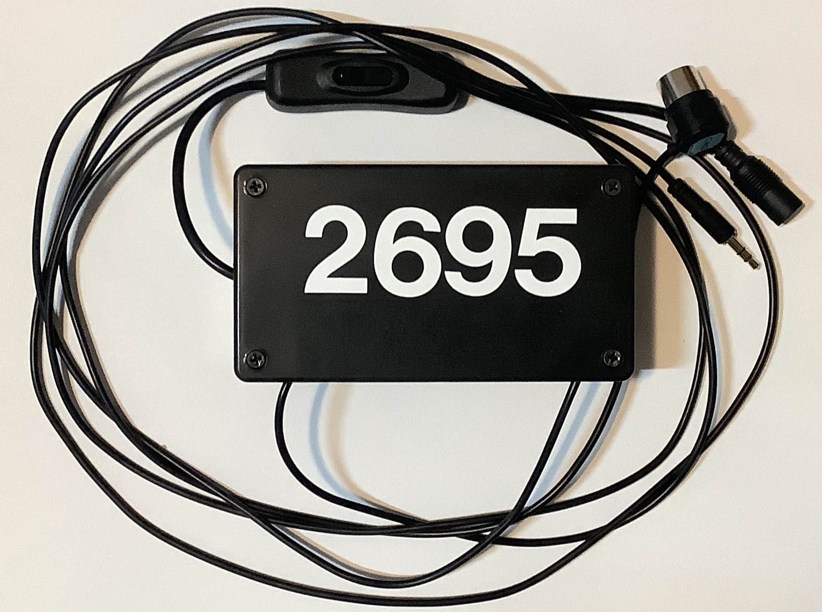
SAM2695 General MIDI tone module
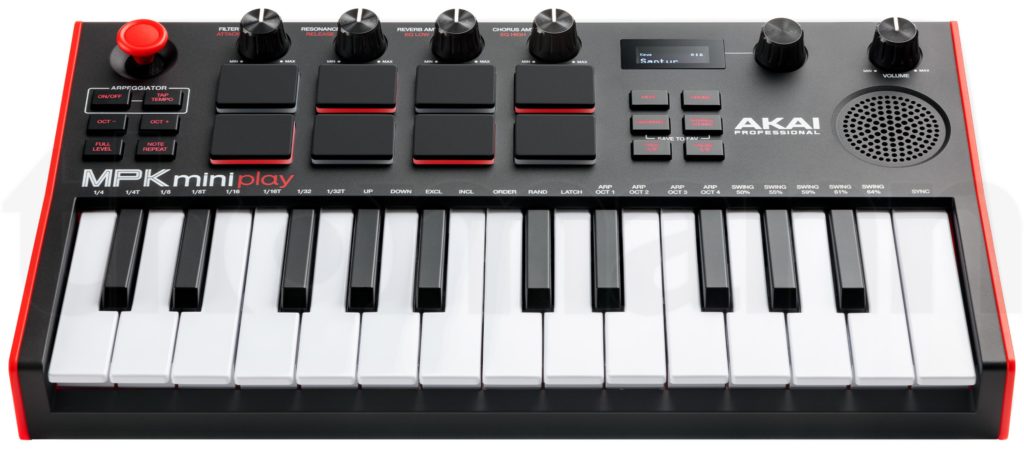
The end result is a GS-compatible General MIDI module which is the size of a guitar pedal. I configured a Novation Launchkey 49 (Mk4) to select 16 GM voices through the pads and to tweak/tweeze a basic set of GM parameters. The Mk4 supports two zones (Part A and Part B), is flexible, and deserves a blog post of its own.
I put the SAM2695 through its paces and confirmed my impressions. (See my post comparing the SAM2695 against the Yamaha PSS-A50.) Not a bad GM module for $50 (total). Still, it won’t have people selling their Nords, Montages, Kronos, whatever. 🙂 There are some decent playable voices and then there are some crap voices.
The SAM2695 effects, in particular, leave me wanting. The 2695 exposes reverb and chorus parameters, but most tweaking requires System Exclusive (SysEx) messages. More ranting about SysEx in a minute.
Relatively speaking, the Yamaha PSS-A50 is not harsh and its effects are better. The PSS-A50 also uses a one-chip solution, the Yamaha YMW830. On the other hand, the A50 MIDI implementation is truly spartan. For example, one cannot change either the reverb or chorus type. The stock A50 is mono (not stereo), so the Yamaha engineers decided not to implement MIDI CC#10 Pan.
Thus, I have really cooled to the idea of hacking the A50 into a module. Why begin a project when you know that the end result will be deficient in a major way?
Which brings me to the third option — chopping up Gakken NSX-39, better known as “Pocket Miku.” The NSX-39 is based upon a different one-chip Yamaha solution, the YMW820 (NSX-1). The YMW820 is a more than decent XG MIDI implementation. It supports the full GM sound set (A50 has 40 selected GM voices) and it has a fair to middling variation effect unit, including rotary speaker!
With all that going for it, the NSX-39 should be a no brainer. Nope. There is no clear, direct way to hack MIDI onto the YMW820. So, it’s likely to be MIDI over USB all the way and the USB port is implemented by an ARM media processor chip fronting MIDI to the YMW820 over SPI. The NSX-39 is already a small board/package and there isn’t much to cut away.
Then there is the issue of that insipid Miku voice. MIDI channel 1 is dedicated to Miku and, without writing the flash ROM, you can’t get rid of it. Yamaha had envisioned Real Acoustic Sound (RAS) as an alternative to Miku, but they never released a ROM image. RAS is a form of Articulation Element Modeling (AEM), also known as “Super Articulation 2“. Here is a video demo (AEM saxophone) of what could have been. [Video courtesy of Ken Fujimoto.]
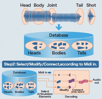
YMW820 Real Acoustic Sound (RAS)
A big issue hanging over all three design options is the inability to send SysEx from the Launchkey. Or, another way of stating the requirement, critical settings need SysEx when most inexpensive MIDI controllers are incapable of sending SysEx. Really, how hard would it be to add SysEx support to a MIDI controller? SAM2695 has two MIDI CCs — CC#80 and CC#81 — which set the reverb type and chorus type, respectively. This capability is very unusual, however.
Yamaha arrangers keep voice set-up data in a few different places. Every voice has a basic set-up in its internal meta-data. One level up in abstraction, each panel voice has a so-called VCE (Voice Edit) file. (“VCE” is one of several file name extensions which denote a Voice Edit file.) The VCE is a MIDI file which selects the base-level voice and then changes EQ, filter characters, attack/release, and insert effect among other things. Styles contain something like a VCE in One Touch Setting (OTS) locations. Registrations can store VCE-like data, too.
The arranger voice design got me thinking. Why not map MIDI Program Change messages to a group of VCE-like MIDI messages in order to set up the SAM2695 (or whatever), i.e., choose reverb and chorus type, tweak EQ, and so forth? My AdaFruit Feather MIDI event processor would be a good platform given the appropriate custom code. A future project?
Copyright © 2025 Paul J. Drongowski