
Time for a quick look at the MODX internal hardware. I’m going to be brief, so please read my Yamaha Genos articles (main CPU and tone generation) and my Montage internals article for more details and background information.
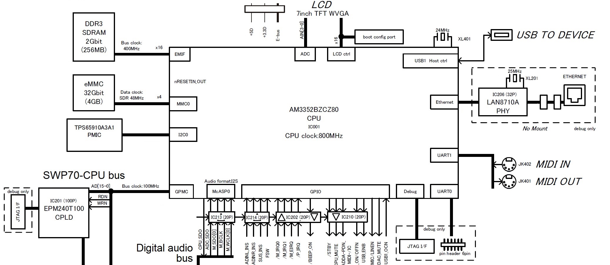
The MODX main CPU subsystem should look familiar. It is essentially the same as the Montage main CPU subsystem. Again, the Texas Instruments AM3352 Sitara ARM microprocessor is the star, providing many of the important internal device interfaces. The eMMC bulk storage device is still 4GBytes although the MODX eMMC data clock is slightly slower than Montage (48MHz instead of 52MHz). Deja vu all over again.
The MODX is a reduced-spec Montage. Although the MODX has the same waveforms and Performances as Montage, its polyphony is less:
- AWM2: 128 (maximum; stereo/mono waveforms)
- FM-X: 64 (maximum)
The keybed is lower quality (semi-weighted vs. FSX) and the MODX front panel is greatly simplified.
Both products employ an MB9AF141NA ARM microcontroller for user interface scanning assisted by an 89FM42AUG logic device (E-GKS) for keybed scanning. User input (e.g., controller messages) are sent to the Master SWP70 tone generator over the EBUS. The EBUS is a low-latency path for controller input and commands, making for a responsive instrument with excellent hand-to-sound connection.
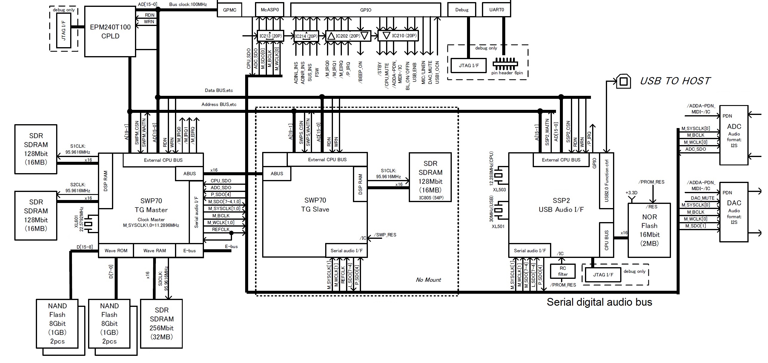
When we look at the MODX tone generation subsystem, we immediately see why the FM-X spec is lower. The MODX has only one SWP70 tone generator integrated circuit (IC). The Master SWP70 performs both AWM2 and FM-X synthesis. The MODX printed circuit board (PCB) has space and connections for a second SWP70 (in Slave mode), but the real estate is unpopulated (“No Mount”). Yamaha have planned ahead for a future model. They did the same thing with the MOX, BTW, leaving space and connections that were filled in the MOXF.
The extra computational capacity within a single SWP70 is surprising! The Master SWP70 provides 128 channels of AWM2 polyphony and 64 channels of FM-X polyphony. In order to pull off this trick, Yamaha utilize a second dedicated DSP RAM channel and SDRAM. Montage, on the other hand, utilizes only one DSP RAM channel on each SWP70.
Thus, the SWP70 can expand in two different dimensions:
- DSP RAM (two dedicated channels max) with a corresponding boost in DSP computation, and
- Wave RAM (two dedicated channels max) with an as-yet unexploited boost in AWM2 synthesis.
MODX illustrates the first case while Montage has an unpopulated position and connections for a second WAVE working memory channel. Your guess is as good as mine as to how Yamaha will expand and exploit these channels in future products.
The MODX serial digital audio bus is a subset of Montage. An SSP2 processor supports audio-over-USB through the USB TO HOST interface, just like Montage. However, the overall spec is substantially reduced. A single DAC drives the MAIN and PHONE outputs. A single ADC encodes incoming stereo audio from the A/D input. The SSP2 does not have a direct channel to an SSP2; the needed logic device is missing from MODX.
In case you’re wondering about serial audio bus clocking, the bus clock is 11.2896MHz. The clock speed is 256 * Fs, where Fs is 44.1kHz. In MODX and Montage engineering-land, this signal is known as M_SYSCLK. Genos engineers refer to this signal as mcasp-256fs. The different terminology doesn’t help comparison across product lines! Bottom line, the master clock is fast enough to support 32-bit 44.1kHz stereo audio. Currently, only the Genos has a 32-bit DAC for its MAIN out, BTW.
Our look inside MODX shows how Yamaha can manufacture the MODX at a lower price point. More significantly, perhaps, is the cost leverage gained by reusing the Montage software and sound content. I think sometimes arguments on the Web play up component cost while neglecting manufacturing, software and sound development costs. I suspect that software and sound development (waveforms, voices, arpeggios, styles, etc.) are a very large fraction of unit cost.
We also caught a glimpse of what’s in store for the future. SWP70 is in early childhood and Yamaha have left room to grow in both the MODX and Montage. In addition to unpopulated PCB sites, Yamaha can build out by using higher capacity NAND flash devices for waveform memory. I’ve said it before — the real limiting factor is Yamaha’s capacity to produce high-quality content — a labor intensive job. Ultimately, the payroll is more important than the cost of commodity NAND flash!
Montage digital audio clocking
I’m still thinking this through…
The Montage USB audio interface supports 44.1kHz, 48kHz and 96kHz sampling frequencies. The number of supported audio channels depends upon the chosen sampling frequency as defined in the specs:
“[Sampling Frequency = 44.1kHz] Input: 6 channels (3 stereo channels), Output: 32 channels (16 stereo channels)
[Sampling Frequency = 44.1kHz – 96kHz] Input: 6 channels (3 stereo channels), Output: 8 channels (4 stereo channels) “
The MODX USB audio interface is strictly 44.1kHz supporting:
“Input: 4 channels (2 stereo channels), Output: 10 channels (5 stereo channels)”
The digital audio bus master clock is a multiple of 44.1kHz, so how does Montage handle 48kHz and 96kHz?
The Montage SSP2 processor handles 44.1kHz, 48kHz, and 96kHz internally. The tone generators, however, are 44.1kHz only. A-ha! That explains the function of Montage’s SRC16 gate array. The gate array is clocked at 49.152MHz, which is a multiple of 48kHz. It converts the sample rates and samples between 48/96kHz and 44.1kHz in DAC-A format (2 channels per line).
The schematic notations on SRC16 match the Montage 48/96kHz spec:
Output: SWP->SRC->SSP2 8 channels (stereo 4 channels)
Input: :SSP2->SRC->SWP 6 channels (stereo 3 channels)
Someday I will explore the Montage/MODX subsystems in more depth.
Copyright © 2019 Paul J. Drongowski
Diagrams are from the MODX Service Manual (copyright Yamaha) .