Random answer day (1)

Maybe it’s the first day of the regular NFL season or the phase of the moon. Here’s a recap of a few questions that came into the forums.

How are arranger/synth preset voices stored? First, one may ask, “How is a preset represented?” Typically, a preset voice consists of waveforms (AKA “samples”) and voice (meta-)data. The voice data control how the sample-playback engine applies filtering, amplitude envelope, modulation and so forth. The waveforms, of course, provide the basic digital audio data.

There is such a broad range of arranger/synth products at different price points, that the amount of storage and the kind of storage varies quite a lot.

The lowest of the low in the Yamaha range: PSS-A50, -E30, -F30, PSR-F51. Presets are stored on a 2MByte serial flash ROM and are loaded into the processor (SWLL) at start-up. The 2MBytes include code, too! Tone generation is integrated into the SWLL. Insanely small, and very low cost.

The highest of the high in the Yamaha range: Genos. Factory presets are stored in four 1GByte ONFI NAND flash devices. Expansion memory consists of two 1GByte ONFI NAND flash devices. Wave memory connects directly to external tone generators (SWP70).

I’ve looked at the diagrams for Genos and I’m not sure about the size and function of those memory units, especially Genos USER memory and expansion memory.

Yamaha confuses people when they speak of “user memory,” “internal memory,” etc. They are usually referring to logical, user visible storage.

When getting down to the hardware level, there are many different physical memory units. since we’re not discussing fairy dust or magic, the logical storage must be assigned to one or more physical memory units. And, of course, the physical memory units themselves may be composed of multiple integrated circuits. The other dimension is “what communicates to what.” Memory is passive and needs a processor to initiate reads and writes and to do something with all that data. At the physical level, a memory unit essentially belongs to a single processing unit (host computer, tone generator) and directly communicate with it.

Sometimes I think of the SWP70 as a parallel processor just like a GPU. The CPU/SWP70 is not exactly analogous to host CPU plus GPU, however. Graphics memory is shared between CPU and GPU. The SWP70 does not share its waveform memory with anybody — it’s dedicated to the tone generator. That’s why installing an expansion pack (voice library) is kind of slow and technically complicated, and why a Genos reboot is required.

Yamaha Genos SWP70 tone generators

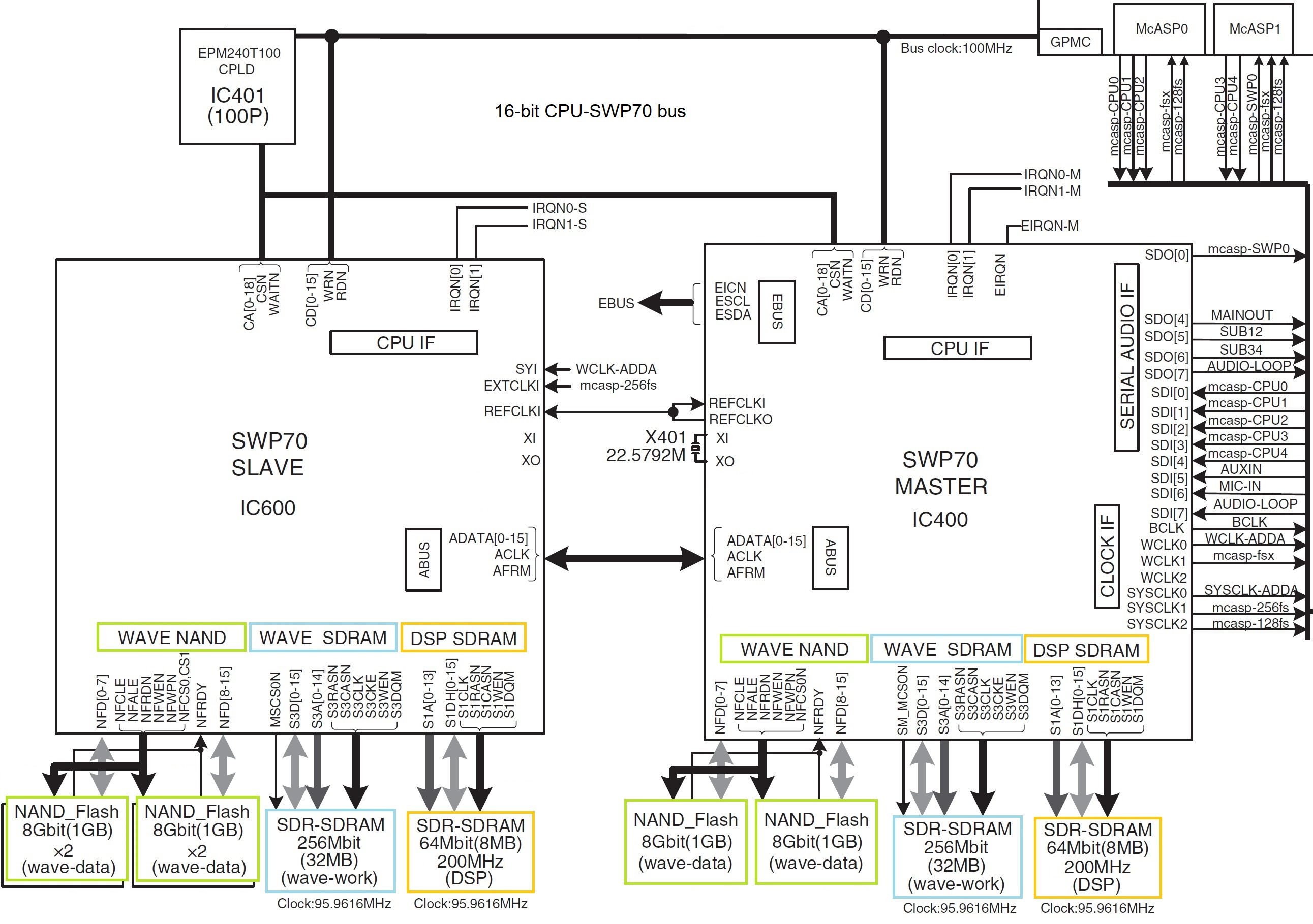
Staying with Genos, Genos has two SWP70 tone generators: one handles factory presets and the other handles user expansion voices. The factory SWP70 has 4GBytes of flash memory while the expansion flash memory has 1GB of flash memory. That’s physical memory. Yamaha boosted the effective capacity to 3GB expansion through compression.

The SWP70s also have DSP RAM. As a user, you never know about this memory. It’s scratchpad memory for DSP effects. Physically, the DSP RAM is completely separate and independent from the waveform memory, and communicates with only its parent SWP70.

Yamaha Genos Host CPU

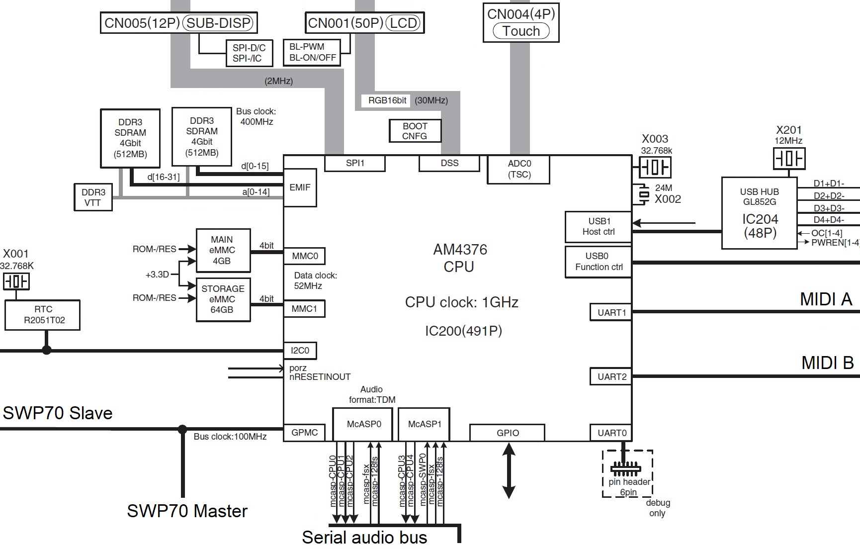
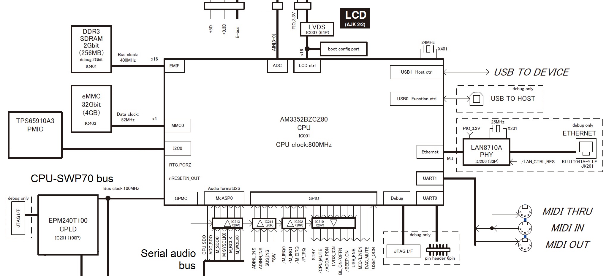
The host CPU has two kinds of memory (as determined by its bus interfaces): 1GB of working RAM on the CPU memory bus (EMIF) and two embedded eMMC memory devices that act like solid state storage drives (MMC0 and MMC1). As far as a user is concerned, the user never sees the 4GB eMMC drive (MMC0) just like you don’t see the DSP RAM; it’s hidden. The MMC0 drive contains the Linux operating system kernel and the root file system.

The user sees only part of the second 64GB eMMC drive (MMC1). The user sees the logical storage which Yamaha calls “Internal memory” or “USER drive.” What’s in the remaining 6GB? I don’t know — Yamaha haven’t left any clues.

What about Montage and its 5.67GByte waveform memory? 5.67GB is the capacity when the waveforms (samples) are compressed. Again, this is logical storage capacity.

Yamaha Montage SWP70 tone generators

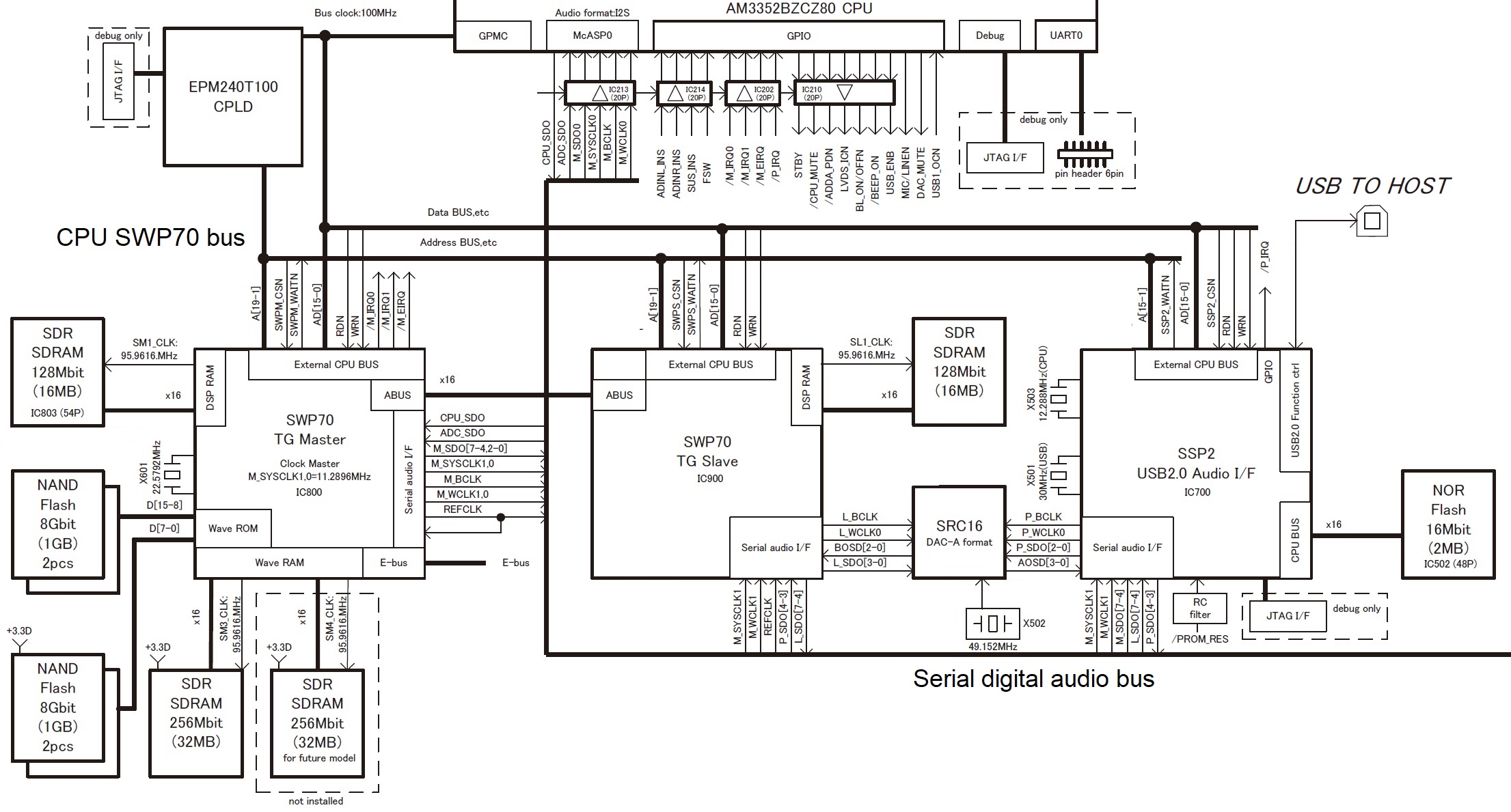
Montage has two SWP70s. One SWP70 is dedicated to FM-X and it does not have waveform memory. The second SWP70 handles AWM2 synthesis (sample playback) and has waveform memory connected to it. The waveform memory consists of four 1GByte devices totaling 4GBytes. Thanks to Yamaha’s proprietary compression, Montage stores 5.67GBytes-worth of data in the physical waveform memory. The remaining space, 1.75GB physical, is available for user samples.

How does sample capacity relate to price? It doesn’t. Component cost is outweighed by manufacturing costs, software development cost and sound design cost.

If the memory components are so cheap, why isn’t there more waveform memory? If there was more, then you wouldn’t buy the Mark II model, would you? 🙂

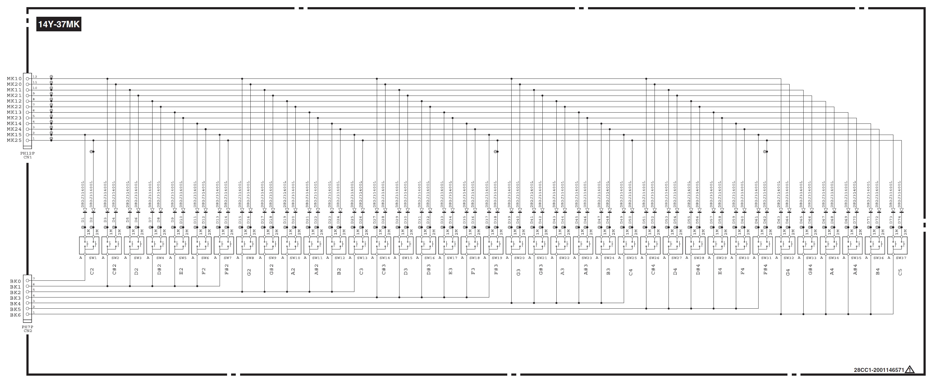
I understand that E30/F30 do NOT offer velocity sensitivity. My question is about the internals. Is it confirmed that it’s a keybed with two switches per key, that just aren’t supported in software?

Yes, you need to be careful here. There are hardware model differences: E30 and F30 are not velocity sensitive. A50 is velocity sensitive.

There are two different keybed printed circuit boards (PCB). Yamaha part number VAY27800 for F30/E30 and VAY28500 for A50. The A50 PCB has the necessary diodes installed for velocity sense. The F30/E30 PCB does not have the diodes. Further, the A50 board has a 12-pin connector while the F30/E30 board has an 11-pin connector — perhaps to avoid assembly mistakes.

Yamaha Reface key switch matrix schematic

Is velocity sense worth the extra bucks? There may be other differences, too, but these differences are plainly visible.

And the usual caution/disclaimer — kiss the warranty good-bye! For the money, the PSS should be good mod-fodder. Korg probably sold a mess o’monotron that way. 

Copyright © 2021 Paul J. Drongowski

Arpeggio to style conversion

Let’s get one out of the vault… 🙂

The Motif XS/XF (MOX/MOXF) and Montage (MODX) arpeggios and performances are a great source of inspiration. Unlike Yamaha’s arranger series, the built-in phrase library is rich in urban and chill patterns. For some odd reason, one of the classic XS/MOX performances — “Dresden At Night” — never made the leap to Motif XF. And, it’s missing from Montage/MODX, too.

A PSR Tutorial forum member sought help resurrecting Dresden At Night, albeit a recreation for the PSR-SX700 arranger. I thought I would help out since I wrote a series of articles about MOX performance to style conversion:

The end result of that work is a small collection of PSR (Tyros, Genos) styles based on MOX (Motif XS) performances.

If you would like to try Dresden At Night or experiment with a conversion of your own, download the free ZIP file.

MOX performances have four parts (voices). Each part has up to six musical phrases (arpeggios) associated with it. Six front-panel buttons select the currently playing set of arpeggios, i.e., button one selects the first arpeggio for each set and so forth. To get the basic MIDI data, I played each arpeggio (group) for four measures while recording in MOX performance quick record mode. I wrote out the MIDI data as a Standard MIDI File (SMF), transfered the SMF to PC, and imported the SMF into a DAW (Sonar).

Dresden At Night is a downtempo (91 BPM), urban-ish chill performance. It has four parts:

Part# Voice    Name              NoteLo NoteHi VelLo VelHi Level Pan
----- -------- ---------------- ------ ------ ----- ----- ----- ---
1 PRE8:070 8Z Heavy Hearts C-2 G8 1 127 81 C
2 PRE3:053 Dark Bass C-2 G8 1 127 51 C
3 PRE7:110 Ibiza Groove C-2 G8 1 127 127 C
4 PRE5:121 Smooth BPF Sweep C-2 G8 1 127 73 C

The first part is the rhythm voice and the second part is the bass voice. As we’ll see below, arpegiation is turned for these two parts. The third and fourth voices are a play-along pad layer and arpeggiation is disabled. Thus, the rhythm and bass parts provide a looped backing while the pad voices provide an atmospheric you-steer-it, right hand part.

Here are the arpeggio assignments:

Arp#1 Tempo:91              Arp#2 
----- -----
1 MA_8Z HeavyHrt1 1 MA_8Z HeavyHrt3 ON
2 MB_WestCoastPop _XS 2 MA_WestCoastPop _XS ON
3 MA_Space Arp 3 MA_Space Arp OFF
4 MA_Up Oct1 4 MA_Up Oct2 OFF
Arp#3 Arp#4
----- -----
1 MA_8Z HeavyHrt4 1 MA_8Z GatedBt3 ON
2 BA_Jazz Pop _XS 2 FB_WestCoastPop _XS ON
3 MA_Space Arp 3 MA_Space Arp OFF
4 MA_Up Oct4 4 MA_Down Oct1 OFF
Arp#5 Arp#6
----- -----
1 MA_8Z ChillBrk4 1 BA_Sp SFX ON
2 MB_WestCoastPop _XS 2 MA_WestCoastPop _XS ON
3 MA_Space Arp 3 Off OFF
4 MA_Down Oct2 4 Off OFF

The Arpeggiator is turned ON for Parts 1 and 2 only.

A big factor is the “8Z Heavy Hearts” drum kit. The “8Z” in its name means “eight zone”. Eight zone (8Z) voices are a Motif innovation beginning with the XS (MOX) family. If you would like more information, check out these earlier posts about eight zone voices:

8Z voices aren’t drum kits. They are implemented as synth voices and are just a clever way of using the eight elements which make up a voice. The eight zones (8Z) are divided across specific note ranges. 8Z Heavy Hearts assigns waveforms (zone sounds) in the following way:

Element#  Note Low  Note High  Waveform 
-------- -------- --------- --------------
1 C0 F#0 Bd T9-1
2 G0 C1 Bd Hard Long
3 C#1 D1 Sd Elec12
4 D#1 F1 Sd HipHop6
5 F#1 A1 HH Closed D&B
6 A#1 C2 HH Open T9
7 C#2 C4 Clap AnSm
8 C#4 C6 Shaker Hip2

Yamaha messes with each of the zones in crazy ways and ties keyboard notes to voice parameters (AKA “key follow”). For 8Z Heavy Hearts, the most notable effect is how the Clap AnSm pitch follows the keyboard.

Arrangers (even Genos!) don’t have 8Z voices. They have standard drum kits where each MIDI note is a separate drum instrument. In order to make a PSR style using a DAW, one must translate the 8Z MIDI notes to standard drum kit notes. You need to assign appropriate drum kits (e.g., DrumMachine, Analog T9, House, Break or HipHop) to style parts 9 and 10 (MIDI channels 9 and 10) and copy the Heavy Hearts MIDI data to both Parts. Then, delete the notes that aren’t needed in a style part, compress each zone into a single drum instrument, and map the resulting “compressed” notes to the appropriate drum instrument(s). So, for example, all of the notes in C0 to F#0 might be compressed into the Kick T9 1 instrument (B0) in the Analog T9 Kit, which is one of the target drum kits.

I found two PSR drum parts to be enough. However, styles are flexible and you could assign a third (fourth, …) drum kit to one of the other style parts. There’s nothing in Yamaha styles that prevents this. It’s just that parts 9 and 10 (MIDI channels 9 and 10) are conventionally assigned to drum parts in a style.

I went with two PSR drum kits: Analog T9 kit and Drum Machine kit. Here is one possible assignment:

Note Low Note High Waveform       Instrument        Note#   Kit 
-------- --------- ------------- ---------------- ------ -----------
C0 24 F#0 30 Bd T9-1 Kick T9 1 35 B0 AnalogT9Kit
G0 31 C1 36 Bd Hard Long BD Hard Long 24 C0 DrumMachine
C#1 37 D1 38 Sd Elec12 Snare Analog CR 63 D#3 DrumMachine
D#1 39 F1 41 Sd HipHop6 Snare Hip 1 86 F#3 DrumMachine
F#1 42 A1 45 HH Closed D&B Hi-Hat Closed Syn 91 A4 DrumMachine
A#1 46 C2 48 HH Open T9 Hi-Hat Open T9 46 A#1 AnalogT9Kit
C#2 49 C4 72 Clap AnSm Clap Analog Sm 27 D#0 AnalogT9Kit
C#4 73 C6 96 Shaker Hip2 Analog Shaker 57 A2 DrumMachine

A lot of detail, huh? Nobody said style conversion was easy. 🙂 In the end, I spread each zone across multiple drum instruments of the same type, i.e., assigning the Shaker Hip2 zone to a few different Analog Shaker sounds in the Drum Machine kit. Part of 8Z Heavy Hearts’ charm is the subtle sonic variation provided by each zone.

Trying to keep this all straight in the DAW piano roll is cognitively challenging. Did I say, style conversion isn’t easy? 🙂

Fortunately, one can loop four bar sections and play the MIDI through the arranger (Genos, in this case) just like a MIDI song. Then, it’s the usual tweak, listen, rinse, repeat edit process. When the MIDI is tweezed to your liking, you need to add MIDI markers to delimit the style sections. (BTW, leave a one bar MIDI set-up measure at the beginning.) Style section markers are:

    Set-up measure 1: SFF1 
Set-up measure 1: SInt
Main sections: Main A, ...
Fill sections: Fill In AA, ...
Break section: Fill In BA, ...
Introduction: Intro A, ...
Ending: Ending A, ...

At a minimum, you need a few MIDI set-up System Exclusive (SysEx) messages at the beginning of the SMF (measure 1, beat 1):

    F0 7E 7F 09 01 F7                 GM Reset 
F0 43 10 4C 00 00 7E 00 F7 XG System ON
F0 43 10 4C 02 01 00 01 16 F7 Reverb type
F0 43 10 4C 02 01 20 16 00 F7 Chorus type

Reverb is the “Light Hall” preset and chorus is the “Tempo Cross 1” preset. The tempo cross delay is an 8-beat echo.

Which brings me to a necessary ingredient: crunch. 8Z Heavy Hearts gets a lot of its appeal from the Lo-Fi effect:

#  Parameter                   Val  Hex   Meaning 
-- -------------------------- --- ---- --------
1 Sampling Frequency Control 4 0x04 8.82kHz
2 Word Length 98 0x62
3 Output Gain 7 0x07 0dB
4 LPF Cutoff Frequency 56 0x38 12kHz
5 Filter Type 1 0x01 PowerBass
6 LPF Resonance 63 0x3F 6.3
7 Bit Assign 4 0x04
8 Emphasis 1 0x01 On
10 Dry/Wet 88 0x58 D<W24
15 Input Mode 1 0x01 Stereo

Since we need Lo-Fi on both style parts 9 and 10, I configured the variation effect as an XG SYSTEM effect. Parts 9 and 10 also require variation send (MIDI CC#94) set to 127. Add a CC#94 message to parts 9 and 10 in the set-up measure. Here are the MIDI System Exclusive messages to add to the set-up measure:

F0 43 10 4C 02 01 40 5E 13 F7       Variation type 
F0 43 10 4C 02 01 5A 01 F7 Variation SYSTEM
F0 43 10 4C 02 01 56 40 F7 Variation return
F0 43 10 4C 02 01 58 10 F7 Variation send to reverb
F0 43 10 4C 02 01 59 10 F7 Variation send to chorus
F0 43 10 4C 02 01 42 00 04 F7 Variation parameter 1
F0 43 10 4C 02 01 44 00 62 F7 Variation parameter 2
F0 43 10 4C 02 01 46 00 07 F7 Variation parameter 3
F0 43 10 4C 02 01 48 00 38 F7 Variation parameter 4
F0 43 10 4C 02 01 4A 00 01 F7 Variation parameter 5
F0 43 10 4C 02 01 4C 00 3F F7 Variation parameter 6
F0 43 10 4C 02 01 4E 00 04 F7 Variation parameter 7
F0 43 10 4C 02 01 50 00 01 F7 Variation parameter 8
F0 43 10 4C 02 01 54 00 58 F7 Variation parameter 10
F0 43 10 4C 02 01 75 01 F7 Variation parameter 15

At this point, you could save the MIDI to “DresdenAtNight.sty” and load it into your arranger as an SFF1 format style. The arranger should create the style CASM segment. As an alternative, you can add a CASM segment to the SMF with Jørgen Sørensen’s CASM editor. You might as well download his OTS editor, too, and use it to add OTS voice settings to the new style as well. Or, you can do this sort of work on your arranger itself. Mid- and high-end Yamaha arrangers save styles as SFF2 format, which is one way to convert from SFF1 to SFF2. I highly recommend Jørgen’s site, tools and style creation tutorial.

BTW, you can recreate Dresden At Night on MODX (Montage). Create a new MODX performance with 8Z Heavy Hearts and Dark Bass. 8Z Heavy Hearts has the appropriate arpeggios by default. You’ll need to assign different arpeggios to the Dark Bass part. Modify effects as needed. Choose and add pad or lead voices to give your right hand something to do. Done! Use the Scene buttons to switch arpeggio groups.

Copyright © 2021 Paul J. Drongowski


Combo organ: Reface YC

Checking out organ-related threads in the music forums, combo organs get short shrift while most folks focus on the Hammond B-3 tonewheel sounds. Today’s post will (almost) ignore the B-3…

Organ-focused keyboards from Nord, Hammond, Yamaha and others have combo organ emulations in addition to tonewheel synthesis. All offer two vintage flavors: Vox and Farfisa. Nord and Hammond throw in pipe organ, piano, EP and instrument emulations, too, making for full all-rounders.

Drawbar control abounds! In the case of Vox, each physical Nord drawbar corresponds to a Vox Continental drawbar footage (with possible extensions). Nord Electro 6, for example, offers 16′, 8′, 4′, 2′, II, III, IV and sine. The 16′, 8′, 4′, IV and sine are basic Continental tones. Nord’s emulation kicks the basics up to dual-manual, Continental II territory by adding a 2′ footage and two overtone mixtures, II and III. The mixtures consist of the following ranks:

  • II: 5 1/3′ and 1 3/5′ pipes
  • III: 2 2/3′, 2′ and 1′ pipes
  • IV: 2 2/3′, 2′, 1 3/5′ and 1′ pipes

The III and IV mixtures add the Hammond-like overtones missing from the original Continental. Hammond employ a similar Vox drawbar assignment in the Sk1/Sk2 series.

Discrete voice (tab) stops pose a minor problem: How to provide discrete On/Off control with sliders (drawbars)? In the case of Farfisa emulation, Nord and Hammond assign each Farfisa tab to a drawbar:

    Drawbar  Farfisa (Nord)  Farfisa (Hammond) 
------- -------------- -----------------
1 Bass 16' Bass 16'
2 Strings 16' Strings 16'
3 Flute 8' Flute 8'
4 Oboe 8' Oboe 8'
5 Trumpet 8' Trumpet 8'
6 Strings 8' Strings 8'
7 Flute 4' Flute 4'
8 Strings 4' Piccolo 4'
9 2 2/3 Strings 4'

The Hammond voice set is the same as the Farfisa Combo Compact. The Combo Compact Deluxe replaced the Piccolo 4′ voice with a bright 2 2/3′ overtone tab, adding a bit of Hammond-like whistle. The Nord voice set covers the Combo Compact Deluxe model.

Yamaha have taken their own approach to combo organ emulation with the YC61. The YC61 synthesizes tonewheel tones through Virtual Circuit Modeling (VCM) that emulates the sound of analog tonewheels and associated circuitry. Vox (YC61 organ model F2) and Farfisa (model F3) sounds are produced using frequency modulation (FM) synthesis. The YC61 also provides a sine wave “combo” model (F1). The YC61 drawbars bring in the usual drawbar footages with the exception of the 1′ drawbar which is disabled in all FM models (F1, F2, and F3).

Gotta wonder if we can port the F1, F2 and F3 FM organs to Montage and MODX?

Thanks to the frapping pandemic, I have yet to play a YC61. (Grrr.) However, I have played the Nord Electro 6D and Hammond Sk1. Both provide excellent combo organ sounds. Pipe organ (Nord and Hammond) is a big plus for a church player. I give Nord’s orchestral samples and library the edge over Hammond.

Yamaha Reface YC

Yamaha Reface YC promises tonewheel and combo organ sounds on the cheap. By and large, it delivers. I have really worked the Reface YC as a rehearsal instrument and as a gig instrument in church. That said, here are some detailed observations (positive and negative).

Reface YC Typical Vox and Farfisa settings (Source: Yamaha)

I roll my eyes a bit whenever anyone posts about how they “wish the Motif XF (Montage, MODX) had the Reface YC technology inside.” News flash, the Reface YC shares much of its technology with Motif XF, Montage and MODX already. Yamaha simply repackaged and revoiced the basic AWM2 DNA in a wonderfully accessible form. Wisely, Yamaha reacted to the warm user reception and reaction caused by the YC and its popular pal, the Reface CP. Yamaha is now taking it to the bank with the current full-sized CP and YC keyboards.

The Reface YC emulates five different organ models:

  • H: Hammond tonewheel
  • V: Vox transistor organ (1960s)
  • F: Farfisa transistor organ (1960s)
  • A: Acetone transistor organ (1970s)
  • Y: Yamaha transistor organ (1972)

The Reface YC drawbars, buttons and sliders directly map to Hammond organ drawbars and controls. What about the combo organs?

I stripped away all of the effects (percussion, chorus, distortion, reverb, etc.) and sampled each of the five voices (8′ foot pipe, middle C). The five waveforms are pictured below. The H and V waves, especially, have a sinusoidal shape. The nasal F wave is truly unique. [Click image to enlarge.]

Reface YC waveforms (middle C, 8′ organ stop)

Since the Vox Continental had drawbars itself, the YC drawbars correspond to a single Vox drawbar sound (the V wave) played back at the appropriate footage (pitch). The YC Vox is based on a single Vox wave, just like the Montage (MODX and Motif XF). In Montage land, this is the “Vx Drawbar1-3” waveform. In the “you get want you pay for” department, the YC Vox does not have the reed and sine drawbars/sounds, and you must dial in the II, III, and IV mixtures yourself.

For the sake of authenticity, one should never put a combo organ through the rotary speaker effect. Trust me. Most of us in the 60s could barely afford an organ and an amp, let alone buy a Leslie. Then there is the issue of getting to the gig. Everything needed to fit into the back of Dad’s car!

The YC Farfisa, Acetone and Yamaha organ implementations follow the same design as the Vox. Each of the four combo organs (V, F, A and Y) consist of a single wave played back at different pitches according to drawbar footage.

Listening to the stripped down F wave, my first thought was “Accordion!” The 60s Farfisa organs were designed by accordion makers and I believe that the raspy Farfisa tone is their intentional attempt to build an electronic accordion. [Memories of Mom and Dad saying, “Why don’t you play accordion and learn a few wedding songs?” Who knew?] The name “Farfisa” is a contraction of “Fabbriche Riunite De Fisarmoniche”, the company formed by pre=World War 2 Italian accordian makers Settimio, Soprani, Scandalli, and Frontallini. It ain’t an accident, folks.

Thus, in terms of control, the Reface YC is quite unlike a real Farfisa Combo Compact with its discrete voice tabs. Once again, you pay more for Nord or Hammond and you get more authenticity. That doesn’t mean you can’t get a decent Farfisa tone out of Reface YC. It’s raspy enough for Wooly Bully and other cover songs. The chosen F wave is versatile and, well, Farfisa voices are pretty much the same wave filtered differently. The screaming Tone Boost is missing in action, though.

I give the Reface YC an A- and B+, respectively, for Vox and Farfisa authenticity. I don’t have any direct experience with Acetone and early Yamaha organs — just the soundtracks of old Japanese kaiju (monster) movies. The YC sounds realistic enough.

I experimented with YC percussion in isolation, too. Each of the Reface combo organ voices has its own distinctive percussion. I recommend trying this at home as some of the settings are almost clav-like and would do in a pinch. A few settings remind me of the 1970s Crumar Roadrunner electronic piano — the most crap-tastic electronic piano ever made. Yes, I owned one, played one, and sold it off as fast as humanly possible. 🙂

After analyzing the Reface YC, I understand better how Yamaha teased organ voices from modest hardware. I also have renewed respect for the Montage (MODX, Motif XF) organ voicing and real-time control. The Montage, MODX and Motif XF have all the sonic materials necessary to meet and/or best the Reface YC. Still, you can’t throw a Montage or a MODX into a tiny bag and jump on the bus, train or plane.

DIY drawbar control

If you want to add a few drawbars via MIDI, try my Sparfun Danger Shield drawbars project. Or, at least read my Sparkfun Danger Shield review.

Crumar D9U DIY MIDI drawbar controller

I also gave the Crumar D9U drawbar kit a spin:

The Crumar D9U is a DIY, Arduino-compatible drawbar kit. This series of articles describe my experience from beginning to end and include C code. Don’t want DIY? Then try the ready-made Crumar D9X.

Copyright © 2021 Paul J. Drongowski

Combo organ: Montage, MODX, Genos

Contemporary workstation instruments offer several options for combo organ emulation. Every workstation has at least a few internal combo organ waveforms. Korg Kronos, for example, has two Vox organ waves built in. Even the lowly Korg microKorg XL+ has two Vox waveforms (DWGS single cycle).

Yamaha MODX and Montage — my focus in this article — have a good variety of Vox and Farfisa waveforms. Yamaha Genos has a lesser endowment as we’ll see. Yamaha Reface YC shares sonic DNA (AWM2 and effects) with the Motif XF and will be the subject of a future post.

Motif, Motif ES and Motif XS

Models in the early Motif series primarily base combo organ patches on two waveforms:

  • Portable Electronic: Vox-y tone
  • Compact Electronic: Farf-y tone

You can hear these waveforms at work in the Tiny Combo Bars 1 performance and the Tiny Combo Bar 2 performance. The patches layer three are more elements playing Portable Electronic or Compact Electronic (respectively). Each element is filtered differently: low pass, band pass and high pass. The net effect is like several distinctive tab stops or drawbars pulled at once.

These waveforms are very old, going back to the original Motif (maybe S80) in the early 2000s. I’ll bet dollars to donuts that the Portable Electronic waveform is the basis for the 60’sOrgan voice (MSB: 0, LSB: 116, PC: 18) in PSR and Tyros keyboards. The 60’sOrgan voice was the sole combo organ mainstay in the arranger line for a loooong time.

Motif XF, Montage, MODX

Motif XF got a big shot of combo juice. Motif XF added several combo organ waveforms:

  • Fr All Tabs
  • Fr Bright Boost
  • Fr Flute
  • Fr String Lo
  • Fr String Hi
  • Fr Trumpet
  • Fr Piccolo
  • Fr Pedal
  • Fr KeyOff
  • Vx Drawbar1-3
  • Vx DrawbarIV
  • Vx KeyOff

The Farfisa (Fr) waveforms support emulation of specific Farfisa features: individual voice tabs (flute, string, trumpet and piccolo), the wicked Bright Boost knee lever, bass keys (pedal), and key off sound. The Fr All Tabs waveform covers one of the most common use cases — all of the tab stops turned on. Subtlety was not a hallmark of sixties combo organ music. 🙂

The Vox (Vx) Vx Drawbar1-3 waveform covers the three Continentel footage drawbars while the mixture drawbar is handled by the Vx DrawbarIV waveform. The Vox waveforms include a Vox key-off noise.

In terms of voice programming, one uses note shift to achieve different footage ranks. Passive filtering is emulated through filter type (low pass, band pass, high pass) and cutoff frequency. Of course, everything can be routed into insert effects for distortion, amp simulation, and other grunge.

Since Montage and MODX inherit all things Motif, these waveforms and the Motif performances are there for you. The Montage and MODX sliders allow control over individual voice elements. For example, choose the Raspy Tabs performance and assign slider control to element level. The Fr Raspy Tabs waveform-to-element assignment is:

El# Waveform     KeyLo KeyHi VelLo VelHi Coarse Level Cutoff XA Ctrl 
--- ------------ ----- ----- ----- ----- ------ ----- ------ -------
1 Fr String Lo C2 G8 1 127 0 97 255 Normal
2 Fr Trumpet C2 G8 1 127 0 82 255 Normal
3 Fr Flute C2 G8 1 127 24 120 236 Normal
4 Fr Pedal C-2 B1 1 127 0 127 160 Normal
5 Fr String Hi C2 G8 1 127 19 24 236 A.SW2 On
6 Fr KeyOff C2 G8 1 127 6 87 80 Key Off

Different tabs are brought in and out by moving the corresponding slider. Assignable switch 2 turns on additional brightness. The low keyboard octaves play the bass (pedal) tones. Overall, this is a fairly controllable representation of a wheezy Farfisa Compact.

Because the sliders are not discrete, you can probably make up Farfisa tones which aren’t entirely authentic. But, really, should one care? 😉

Vox performances have similar control-ability. Here is the waveform-to-element assignment in the Vx Full Bars performance:

El# Waveform      KeyLo KeyHi VelLo VelHi Coarse Level Cutoff XA Ctrl 
--- ------------- ----- ----- ----- ----- ------ ----- ------ -------
1 Vx Drawbar1-3 C-2 G8 1 127 0 75 255 Normal
2 Vx Drawbar1-3 C-2 G8 1 127 12 77 255 Normal
3 Vx Drawbar1-3 C-2 G8 1 127 24 91 255 Normal
4 Vx DrawbarIV C-2 G8 1 127 0 127 250 Normal
5 Vx KeyOff C-2 G8 1 127 4 68 85 Key Off

The first three sliders control the 16′, 8′ and 4′ Vox drawbar settings and the fourth drawbar controls the Mixture (IV) tone. Go ahead, just everything to eleven. 🙂

Montage and MODX FM

But, wait, there’s more! Montage and MODX have two FM combo voices: BOX FM Combo Organ and FM YC Combo Organ. Although these performances don’t sound authentic to my ears, they provide starting points for further programming. I haven’t heard the YC61 as yet, but I wonder if the YC61 combo emulations can be ported to Montage and MODX?

Genos

As I mentioned earlier, the arranger series has been historically short on combo organ sounds, relying on the old 60’sOrgan voice. Wheezy, raspy Farfisa tones are noticably absent. The 60’sOrgan voice sounds like the Portable Electronic waveform on which the Motif 1967 Keys performance is based.

Tyros 4 and Motif XF were introduced at approximately the same time. They certainly were together in the development lab during late 2009. Tyros 4 added four combo organ voices:

  1. 60sComboOrgan1: VoxContiComb1_Full_NoVib waveform
  2. 60sComboOrgan2: VoxContiComb1_Full_VibOn waveform
  3. 60sComboOrgan3: VoxCombi4NoVib waveform
  4. 60sComboOrgan4: VoxCombi4NoVib091117 waveform

Voices 1 and 2 capture one Vox Continental drawbar combination (Comb1) and voices 3 and 4 capture a second combination (Combi4).

Voices 1 and 3 are without vibrato. Voices 2 and 4, unfortunately, have an excessive amount of vibrato — almost painfully so. When I use voices 2 and 4 in a MIDI sequence, I dial down the vibrato depth using MIDI CC#77 messages. Vibrato frequency is about 5Hz. I also remove touch sensitivity by setting:

  • Velocity sensitivity depth to zero, and
  • Velocity sensitivity offset to 114.

An organ voice should not respond to touch (key velocity) — ever.

PSR, Tyros and Genos players shouldn’t forget the “hidden” Italian 60s organ voice (It60’sOrgan) in the GM2 sound set. On PSR and Tyros, you’ll find It60’sOrgan within the Legacy voices Organ subfolder. On Genos, you need to download GM2 and XG user voices to the USER voice folder. (See this thread in the PSR Tutorial Forum.) Of course, you can select
It60’sOrgan from a DAW (MSB: 121, LSB: 2, PC: 17) .

All-in-all, you can get a nice Vox tone out of Genos. Farfisa is still missing in action, tho’. Kind of an odd shortcoming of a keyboard with styles and a user base that want to play popular hits from days past.

In the next post, I’ll compare Reface YC combo organs against Montage/MODX (Motif XF). The result may surprise you.

Copyright © 2021 Paul J. Drongowski

Early wave table and FM synthesis

Discussions about Yamaha Montage/MODX AWM2 and FM-X sent me digging into the past to unearth early AWM and FM implementations in order to get insight into today’s tone generation hardware. Although Yamaha do not publish design information about their proprietary SWP, SWX, SWL, etc. processors, they have published datasheets for their merchant line of LSI products. Yamaha were very active in the mid- to late-1990s when desktop music (Soundblaster, XG, Sondius, etc.) was king.

The Yamaha YMF278B OPL4 was one such LSI component. The OPL4 combines a 2-/4-op FM synthesizer and a wave table synthesizer on a single 80-pin quad flat pack (QFP). The FM synthesizer can:

  • Generate 18 voices in 2-op modes or 15 2-op voices plus five rhythm sounds.
  • Generate 6 voices in 4-op mode with an additional 6 voices in 2-op mode, or 6 voices in 4-op mode with an additional 3 voices in 2-op mode and five rhythm sounds.

The FM synthesizer has eight selectable waveforms and generates a stereo output. The wave table synthesizer can generate 24 voices simultaneously (i.e., 24 voice polyphony) producing stereo output at a 44.1kHz sampling rate with bit depths of 8-, 12- and 16-bits. Wave ROMs up to 32Mbits are supported with up to 512 wave tables.

The OPL4 has six sound channels which can be sent to an external DAC (YAC513) or a digital effects processor (YSS225). Sadly, documentation for the YSS225 cannot be found on-line. The YSS225 is said to perform reverberation, echo, flange and other effects.

The FM and wave table synthesizers are two separate hardware units. I wouldn’t be surprised if this is still the case in the modern day SWP70 Standard Wave Processor. Separation lets the engineers optimize the synthesis hardware for a particular synthesis type.

Wave table synthesis

The OPL4 does not implement AWM2 synthesis. The synthesizer does not have the AWM2 filter hardware. This is not too surprising because in that era, Yamaha regarded AWM2 and its analog-like filter as a special competitive advantage. Why would they give that same advantage to other sound card vendors? It’s a safe bet, however, that the XG-compliant variants are full AWM2.

Nonetheless, a peak inside gives us a look at Yamaha’s wave table machinery. The synthesizer consists of a synthesis core that fetches waveform samples and waveform meta-data from external wave memory.

YMF278B block diagram

Quoting the OPL4 data sheet:

The wave table synthesizer can generate up to 24 sounds simultaneously. Each sound is referred to as a “channel”. The channels are numbered from 1 to 24. These numbers are called “channel numbers”.

Wave table synthesis is controlled by a few hundred registers. The main control CPU writes common and channel-specific synthesis parameters into the registers. The synthesizer reads the registers during each synthesis macro-cycle and produces a new sound sample for each channel. The channel-specific control registers are organized into register groups. Each group consist of 24 registers, i.e., 24 values of a specific synthesis parameter type, one value per channel. A quick glance at the table below clarifies the register organization and the wave table synthesis parameters. Parameters for envelope generation, pan, LFO control, etc. are easily identifiable. (The YMF278B data sheet has the details).

YMF278 wave table synthesis control registers

I conjecture that today’s SWP70 is organized in a similar way. The CPU-SWP70 communication bus is a memory bus that gives the CPU direct access to the SWP70 synthesis control registers. Think about it. With 128 stereo AWM2 channels, there are several hundred (thousand!) synthesis values which must be configured at the hardware level. Software’s job is easier and fast by making the synthesis registers (channel-specific parameter value) directly accessible.

Wave table in external memory

The waveform data and meta-information in external memory cosnsist of two parts: Up to 384 waveform headers and the waveform sample data. Each waveform header is 12 bytes containing:

  • Wave data start address
  • Loop address
  • End address
  • Voice parameters: LFO, VIB, ADSR, etc.

Today’s wave table is probably similar albeit much bigger. Explore Yamaha’s Universal Voice Format (UVF) and you’ll see what I mean.

FM synthesis

The OPL4 supports 2- and 4-op frequency modulation (FM) synthesis. Quoting the data sheet:

The part that generates one sine wave is called an “operator”. A combination of these operators is called an “algorithm”. The first stage operator (see diegram below) is called the “modulator” and the second stage operator is called the “carrier”. The frequency and envelope can be set for each operator. “Feedback FM” is available to generate a wider range of sounds.

Basic FM system
Feedback FM system

Like the wave table synthesizer, the FM synthesizer has a large table of common and channel-specific synthesis parameters. The register table organization is a little more complicated. Quoting:

The OPL4 has 36 circuits that generate a sine wave. A circuit which generates a sine wave is called a “slot”. A sound unit which is generated by combining two or four operators is called a “channel”. There are two kinds of sound generation control registers: registers settable in slot units and registers set in channel units.

In 2-op mode, two slots are used to generate on FM sound. With 36 available slots, 18 channels of sound can be generated. In 4-op mode, four slots are used to generate one FM sound. Six channels are generated using 24 slots.

YMF278 FM synthesis control registers

Whew! Given the two dimensional nature of register organization, addressing a specific parameter value for a specific operator is a complicated matter. (See the data sheet for details.) Without going a deep dive into register addressing, here is an image showing common and channel-specific synthesis parameters.

YMF278 4-op algorithms

Summary

I would say that the overall architecture today (SWPxx) is not unlike the architecture of yesteryear. The number of synthesis parameters, of course, has exploded with new features in the wave table synthesis hardware (filtering!) and FM synthesis hardware. Modern FM can route FM output samples to AWM2 wave table filters, adding many wrinkles to datapath and control design.

The main CPU is responsible for channel allocation as notes are played and for channel deallocation as notes are released and completed. Once a channel is allocated, the main CPU must write the appropriate voice parameters into the channel registers. Then, it’s up to the synthesizer hardware to crank out a new sound sample at a 44.1kHz rate. Of course, the per-channel sound samples must be mixed and routed to the DSP effects processors. I would love to get a look at the mixing and DSP processing.

I hope this trip into the past gives you some insight into present-day AWM2 and FM-X hardware and an appreciation for the complexity and sheer number of details at the 10,000 foot level of digital synthesizer design.

Copyright © 2019 Paul J. Drongowski

Yamaha hold many patents on wave table and FM synthesis techniques. I recommend U.S. Patent 5,250,748 (1993) which describes the digital filter in AWM. For the modern era, I suggest U.S. Patents 8,779,267 (2014), 8,957,295 (2015) and 9,040,800 (2015).

Musing about Montage VA

There’s been an extended discussion in the YamahaSynth.com Montage Forum about the ability to add Virtual Analog (VA) synthesis to the current Montage and MODX platforms. It’s been a good discussion and it encouraged me to jot down a few musings about the hardware support for AWM2 and FM-X.

In case you don’t visit YamahaSynth.com, I reposted my musings here and added a diagram or two.

Before saying anything, I have to emphasize “Speculatively speaking.” With as much invested in AWM2/FM-X and their implementation in silicon, Yamaha have not published about the internal design. This whole discussion — including my own comments — would be on much sounder footing (no pun intended) if the micro-architecture were published. Yamaha are tight-lipped so “Hah!” to us all. 😀

BTW, we’re lucky that we can speculate at all since Korg, Nord, etc. have largely buttoned up their service manuals.

I’m skeptical

I’m skeptical about adding VA through an update given the current platform because of limitations in the current synthesis pipeline.

Yamaha regard their expertise in large scale integration as a strategically important asset. (Please see their annual financial reports.) The SWP70 is a major investment in the future. It’s a generational step and a design with a long expected life time. A long life is needed in order to recoup Yamaha’s investment. Thus, we haven’t seen all of its potential capabilities as yet.

At some point, the current hardware platforms (Montage and MODX) will limit the features which can be delivered solely through software. That will necessitate a new hardware model in each product line. Speculatively speaking, I’m not sure if the SWP70 is capable of CS-like VA synthesis. The Reface CS (and DX) employ a Yamaha SSP2 (SH-2 CPU core) for synthesis. The mere presence of an SSP2 in the Montage is not significant for VA because it clearly supports UR-like digital audio in the existing design.

Of course, business decisions will take precedence eventually. We all love the free updates and improvements in our instruments. (I certainly do!) Like cellphones, tablets and other high-end electronics which enjoy periodic updates, we will need to buy a new upgraded platform in order to fuel the future. Nobody rides for free forever.

My mental model

I suspect that we nerds (and I mean that as a compliment!) have different architectural models in mind as to the SWP70 internals. One model is the “standard DSP” model — a pipelined single instruction, single data (SISD) CPU. Naturally, there may be enhancements for vector processing instructions and so forth.

An example of such a generic model is the Yamaha SSP2, which consists of an SH-2 DSP core and several effect DSP processors. The SSP2 is the heart of Reface CS with an internal clock of 135.4752MHz (a multiple of 44,100Hz, BTW). Another example would be the DSP56362 in early Nord/Korg modeling keyboards. The Reface CS manages 8 voices of polyphony (using the word “voice” loosely) with the effects handled by the SSP2 effect DSP processors. (The effect DSP processors are mini, small core, reprogrammable processors.)

The architectural model which I think is used in the SWP70 is a SIMD architecture more akin to a GPU. The Montage/MODX DSP RAM and wave work RAM memory clock is 95.9616.MHz, also a multiple of 44,100Hz. The SWP70 pumps out a finished sample every 2,176 memory clock ticks. The internal clock is probably a small multiple (maybe two) of the memory clock. Everything needs to run in a modest power envelope without a heat sink, etc., so it’s not possible to run at GHz rates.

After writing this, I realized that the AWM2/FM-X synthesis core may not have an instruction stream at all. It might be a block of 1 to N dedicated pipelines where each pipeline is, roughly speaking, an AWM voice element.

I image a block of tone generation (TG) cores dedicated to AWM2/FM-X. Part of that “dedication” is a pipeline specifically tailored and tuned to AWM2/FM-X. (I believe this design IP (the basic core design) is re-used in other AWM2 products.) Yamaha are in the AWM2/FM-X business so it makes sense to design hardware specific to these tasks. It’s no simple feat to produce 128 channels of tone generation with low latency and no burps and hiccups.

I don’t know how much flexibility is built into the so-called “oscillator” part of a TG core pipeline. Could Yamaha write a new SIMD program for VA using the existing TG core design? I don’t know and hence, my doubt.

That said, since Yamaha haven’t published a darned thing and my job easier (Hah!), I could be totally wrong. Yamaha are smart engineers, especially at the hardware level.

The choices made for Reface may or may not be revealing. Reface YC/CP use the SWX08 for AWM2/SCM synthesis. The SWX08 — in my imagination — use a similar AWM2 TG core assist. Reface DX/CS use SSP2 and its SH-2 core. Was something missing in the SWX08 TG core which was available later in the advanced SWP70 cores? Did SWP70 become VA capable as well?

Example: Yamaha YMW820

The closest I’ve ever gotten to understanding Yamaha’s approach to AWM2 is by studying the datasheet and MIDI spec for the YMW820 (NSX-1). Admittedly, the YMW820 is a low-end device implementing a large subset of the XG voice architecture with only chorus, reverb and a single variation effect.

YMW820 (NSX-1) block diagram

The YMW820 has a control CPU (dual issue, 32-bit RISC), mixer hardware, DSP for effects, and a “wavetable synthesis core” (Yamaha’s exact terminology). Both the synthesis core and DSP are controlled by the CPU.

The wavetable synthesis core supports 64 channels (polyphony). The YMW820 has a 2MByte wavetable ROM which presumably contains the General MIDI waveforms. It also has a 3 MByte wave RAM which can be loaded with eVocaloid waveforms or Real Acoustic Sound (Articulation Element Modeling).

The 64 channel synthesis core is drawn as a distinct hardware subsystem from the effects DSP. Each channel is what we consider an element: pitch generator, oscillator, digitally controlled filter (DCF), envelope generator (EG), LFO. I suspect that other AWM2-based products have similar wavetable synthesis cores, including the SWP70. [Click image below to enlarge.]

YMW820 (NSX-1) synthesis core and effect DSPs

Of course, the SWP70 synthesis core is the ultimate in the entire AWM2 family. It also has many effect DSPs for system and insertion effects.

Bottom line, Yamaha exploit massive parallelism for AWM2 synthesis where each channel is a wavetable synthesis element. A true DSP processor like the SSP2 is better suited for VA synthesis which is why the SSP2 is deployed in the Reface CS, not an AWM2-oriented SWX processor. (The SWX has an embedded wavetable synthesis core, too.) I believe that Yamaha will need to add another SSP2 (or some such) to the Montage in order to implement VA. There’s a reason why it’s called a “Standard Wave Processor” — it is hardware specifically designed for AMW2, FM-X, AEM, and SCM synthesis. It isn’t a general purpose programmable DSP. Maybe VA can be warped to the existing pipeline(s), maybe not.

BTW, the new VCM MINI FILTER and MINI BOOSTER are DSP effects. The effect DSPs are programmable — the AWM2 channel filters likely are not.

Big DSP vs. little effect DSPs

I tend to think of the internals as a tone generation front end followed by a flock of small DSP units in the mixer/effects back-end. This seems to be the canonical Yamaha pipeline. In Montage/MODX, some of the small DSPs are routed as insert effects and some as system/master effects. (The effect routing in Genos, BTW, is different and probably different in the high-end digital pianos.) I suspect that the data flow is predominantly (solely?) front to back.

I don’t really know if the small effect DSPs are general purpose or not.They are probably small simple cores because an SWP has at least 15 and real estate is limited. (Lower capacity parts like the SWXs and SWLs have far fewer small DSP cores.) A small core may not have much throughput and the front-to-back dataflow might prevent feeding data from the DSP cores back to the filters, etc. in the front-end.

There is also the issue of getting note and controller data to the effect DSPs in the back end. Note and controller data are delivered on the E-bus directly from the key, knob, slider, etc. scanning processor(s) to the tone generation core. Does all E-bus data get back to the small DSP cores? Certain some data gets through as knobs, sliders, etc. can tweak effect parameters in real-time.

Overall, even as a consumer, I would be happier with a dedicated SSP2 for VA. The VA SSP2 would inject its digital output stream into the existing mixer/DSP infrastructure. [The SSP2 vocal harmony processing does something like this in Tyros5.] The VA SSP2 gets its own DSP RAM and NOR flash for program, and the processing is totally out of the way of FM-X and AWM2. It would be possible to implement different VA algorithms without making compromises. Yamaha could periodically offer new engines as updates/upgrades.

If you’re an ARM aficionado, you might be thinking “big.LITTLE”. It’s a similar concept. Engineers need to make best use of limited real estate. Yamaha need lots of little DSPs for insertion effects. The SSP2 itself is organized as a big SH-2 DSP core and several little effect DSPs (plus a digital mixer). The mix of channel strip and guitar effects is limited.

Down memory lane

The discussion took me down memory lane to the venerable AN-200 and PLG150-AN. Both products use Yamaha’s AN (Analog Physical Modeling) daughter card. I love the old AN-200 and keep one handy. It is a pretty decent approximation of a five voice Prophet 5.

The daughter card contains two Yamaha LSI components:

  • YSS-236-F: An enormous 160 pin QFP for analog synthesis
  • YSS-233-F: A merely huge 128 pin QFP for mixing and effects

The 236 is also known as the “VOP3” and the 233 is known as the “MDSP”. The MDSP is deployed in the PLG150-DX daughter card, again in the mixing and effects role. The An1x, by the way, has two of each, implementing ten voice polyphony.

Some sites ascribe synthesis to the Hitachi H8/3002 on the daughter card. This is wrong. The H8/3002 is the microcontroller that issues commands and maintains digital communication with the mothership. The VOP3 does synthesis.

The VOP3 moonlights as the vocal harmony processor in early arranger keyboards like the PSR-9000. The VOP3 is the predecessor to the SSP and SSP2. The SSP and SSP2 subsume the mixing and effect DSP roles of the MDSP. Such is the march of large scale integration (LSI) fabrication technology.

Given this history, I’m not surprised that Yamaha chose the SSP2 for Reface CS.

I like surprises

Watch, Yamaha will come up with something completely different. 😀 Maybe an SWP71. There were different spins of the SWP50 family, so why not? 🙂 From the marketing point of view, demand for VA is sufficiently high that they may require everyone to buy a new platform anyway. Perceived value means “mo’ money.”

Copyright © 2019 Paul J. Drongowski

Yamaha Montage: Internals revisited

I liked the Genos block diagrams which I posted the other day. The diagrams summarize the Genos main CPU and tone generation subsystems in a compact form.

So, let’s move on to Montage. The diagrams below are taken from the Yamaha Montage Service Manual. I scrubbed non-essential detail (e.g., power rails) in order to focus on the overall digital system organization.

The internal design of mid- and high-end synths and arrangers separates neatly into a main CPU subsystem (running Linux) and a tone generation/digital audio subsystem. Genos, Montage and MODX fit this design pattern.

[Click images to enlarge.]

The Montage main CPU is a Texas Instruments AM3352. Montage has a slightly lower clock rate: 800MHz vs. 1.0GHz (Genos). I don’t think the difference in clock speed is significant because the main CPU generally doesn’t perform compute intensive tasks. (The tone generator circuits and the audio DSP do the heavy lifting.) The main CPU handles sequencing, user interface, the file system, etc.

The AM3352 is an ARM Sitara Cortex-A8 32-bit “system on a chip.” The AM3352 is designed for embedded applications and as such, it has many integrated input/output (I/O) interfaces. The main interfaces are:

  • Primary working memory (EMIF)
  • Touch panel and display (LCD)
  • Bulk memory (MMC0)
  • USB to device interface (USB1)
  • MIDI I/O (UART1)
  • Serial digital audio bus (McASP0)
  • CPU-SWP70 bus (GPMC)
  • Power management (I2C0)
  • General purpose I/O (GPIO)

Having so many interfaces in one integrated circuit (IC) package lowers cost signficantly.

Memory resources are modest. Primary memory is only 256MBytes. Bulk storage is provided by a 4GByte eMMC embedded memory device. Linux and user data (performances, songs, arpeggios, etc.) reside in the eMMC device. Please note that the bulk memory bus (MMC0) has a relatively slow clock speed (52MHz) and width (4 bits). Simply put, this bus cannot support real-time sample streaming for synthesis. [Please stop ranting about this on the Web.] Instead, waveform samples are stored in NAND flash connected to the Master SWP70 tone generator.

Speaking of tone generation, the main CPU is connected to two SWP70 tone generation ICs by the CPU-SWP70 bus. The bus is mediated by a programmable logic device (CPLD). The bus clock is 100MHz. The bus has 19 address bits and the data path is 16 bits wide. The CPU sends control data to the SWP70s through this bus. Also, the main CPU loads samples into NAND flash using this bus. I doubt if this bus could sustain high volume sample streaming in real time.

The CPU-SWP70 bus is organized as an addressable memory bus. (The ARM acronym “GPMC” means “General Purpose Memory Controller.”) Instead of ordinary memory, I believe that the CPU-SWP70 bus provides direct access to thousands of synthesis control registers for AWM2 and FM-X. Check out the huge list of synthesis parameters in the MIDI section of the Montage/MODX Data List PDF. Each parameter controls some aspect of AWM2 or FM-X synthesis. These parameters need to be loaded quickly into the the SWP70 tone generation blocks. Addressable control registers provide the appropriate mechanism.

There are two other major busses in Montage: the EBUS and the serial digital audio bus. (More about the digital audio bus in a second.) The EBUS is driven by an ARM architecture microcontroller (MB9AF141NBPQC) which scans knobs, sliders and switches. The EBUS sends user input to other components, most notably the SWP70s. Thanks to the EBUS, user inputs are quickly acquired and sent to the tone generation process, thereby minimizing latency. This fast path is an important aspect of Yamaha’s design.

On to tone generation and digital audio!

High-end Yamaha synths and arrangers have two SWP70 (“Standard Wave Processor”) tone generation chips. One SWP70 is the Master and the other SWP70 is the Slave. “Master” and “Slave” refer to the communication relationship between the two components. The Master generates the reference clocks for both the Master and Slave, and it generates the clock for the serial audio bus.

In Montage, the Master SWP70 performs AWM2 synthesis and the Slave performs FM-X synthesis. The Master has waveform memory; the Slave does not. Waveform memory isn’t required for FM-X synthesis, apparently.

Both the Master and Slave SWP70s have 16MBytes of DSP RAM apiece. The DSP RAM provides big, fast random access storage for effects processing. Time-based effect algorithms like reverb and delay need a large amount of memory space. The DSP RAM does the job.

The Master SWP70 has two additional kinds of memory: Wave ROM (4GBytes physical capacity) and Wave RAM (32MBytes). [The Genos designers use slightly different terminology for these units, but the functionality is the same.)

Wave ROM is Open NAND Flash Interface (ONFI) compliant. This is the same commodity NAND flash built into PC solid state drives. Instead of using a solid state drive and a SATA bus, Yamaha have built the controller and data cache into the SWP70. This design eliminates the cost, power consumption and delay of a PC solid state drive controller. The Wave RAM is the data cache, holding the currently used samples needed for AWM2 synthesis.

Why a data cache? NAND flash has two major drawbacks. First, writing to NAND flash is slow. Second, random read access to NAND flash is much slower than sequential block access. In fact, random access is too slow for direct streaming into synthesis. The SWP70 pre-fetches blocks of samples into fast Wave RAM which, in turn, provides fast random access to samples. This two-level storage organization supports the high read bandwidth required for 128 lanes of stereo AWM2 synthesis.

The SWP70 has two independent Wave RAM channels. Only one of these channels is populated in Montage. The second Wave RAM unit is not installed and is reserved for a future model. We haven’t seen the full power of the SWP70 generation — yet.

Montage has a power digital audio subsystem which is interconnected by the serial digital audio bus. The CPU, SWP70s and SSP2 chips transfer digital audio on the serial audio bus. These units send audio to the digital-to-analog converters (DACs) and receive audio from the analog-to-digital converters over the bus. The main audio streams are:

  • The main CPU receives audio from the AD INPUT ADC and the Master SWP70.
  • The Master SWP70 receives audio from the main CPU and the AD INPUT ADC.
  • The Slave SWP70 receives audio from the SSP2.
  • The SSP2 receives audio from the Master SWP70 and the Slave SWP70.

The Master SWP70 sends digital audio to the two DACs (assignable output and main output, respectively). The DACs and the ADCs are on a separate circuit board away from the digital electronics (Pure Analog Circuit).

Montage has an SSP2 processor dedicated to USB2.0 audio I/O. It’s like having a mini Steinberg UR interface inside. The SSP2 is the source of Montage’s audio prowess. The SSP2 is a fairly beefy computational engine having an SH-2 CPU core (135.4752MHz internal clock). It is the computational engine in the high-end Steinberg UR series, the Reface DX and the Reface CS. Its role in Montage is like a UR — high speed, multi-channel USB audio. This is why the SSP2 supplies the Montage USB TO HOST interface. Digital USB audio has a direct path to the USB HOST.

The SSP2 gets commands and transfers data with the main CPU over the CPU-SWP70 bus.

I hope you have found this quick tour to be informative and helpful. Yamaha had a few other tricks up its sleeve as we shall see when I discuss MODX specifically. Take care and stay tuned for the MODX update which is about to drop.

Copyright © 2019 Paul J. Drongowski

Diagrams are Copyright Yamaha

Yamaha Genos, Montage, sample compression

Sample compression is a bit of a hot topic among tech heads on the PSR Tutorial Forum and the YamahaSynth.com Forum.

Yamaha recently pre-announced the Yamaha Genos V2.0 update. Features will include:

  • Increased expansion memory from 1.8GBytes to 3.0GBytes
  • Genos V2.0 Superior Pack (50 styles, more than 25 voices including SuperArticulation 2)
  • Chord Looper
  • Style Section Reset
  • Scale Tune Separation

The update will be available during Winter 2019. The scope of the update has caused much excitement as well as a lot of good feeling because Yamaha views Genos as an update-able platform, not a one off. I’m looking forward to the Genos update and the upcoming MODX update, too.

The Superior Pack likely will be an expansion pack containing new styles and voices. Putting the new content in an expansion pack is the easiest way to distribute the content. A user simply puts the expansion pack installation file on a USB drive, inserts the drive into Genos, and runs the on-board Genos installation procedure. The installation process is tried, true and mature.

Of course, this raises the question of expansion memory space and how to make best use of it. Would or should someone install the Superior Pack and always keep it around? Will there be enough space for other packs? Some people are pack rats (pun intended) and want to keep everything loaded. Increasing the expansion memory from 1.8GBytes to 3.0GBytes takes a little pressure off the pack rats.

Naturally, the increase in expansion memory piques the tech heads. How did Yamaha increase the expansion memory space? One cannot snap fingers and add physical memory to Genos. This is a software update, after all.

One theory has to do with sample compression. Yamaha’s expansion packs typically use two sample formats: LINEAR16_FRAME and WXC. WXC is Yamaha’s proprietary sample compression format. WXC is treated like a closely guarded secret. WXC is the way to pack voice waveforms as tightly as possible within the limited physical capacity of wave memory. It’s part of Yamaha’s secret AWM2 sauce.

User samples, on the other hand, are not compressed and are stored in LINEAR16 format. Currently, when Yamaha specifies the size of Genos expansion memory, they mean the ability to store approximately 1.8GBytes of uncompressed user samples in expansion memory. Since users can’t compress their samples via YEM (or whatever), Yamaha doesn’t want to disappoint them by overstating expansion memory capacity and then underdeliver on their spec.

So, is the increase achieved through sample compression, i.e., restating the capacity as 3.0GBytes using the well-known qualifier “when converted to 16 bit linear format?” WXC compression can easily squish 3.0GBytes of samples into 1.8GBytes. Or, have Yamaha found and allocated extra space to user samples? In the latter case, the extra space must be in the NAND flash memory which holds the factory waveforms. This is left-over space and assumes that Yamaha left quite a bit of slack in the 4GBytes holding the factory waveforms.

Now we get to the point of contention among Montage/MODX tech heads. If Yamaha have found a way to support compressed user samples on Genos, can the same technology be ported to Montage and MODX?

The answer partly depends upon the means by which Yamaha provide sample compression itself. (Remember, sample decompression is built into the SWP70 AWM2 hardware.) YEM is an established application in the Genos software eco-system. Yamaha could add the compression algorithm to YEM. In the case of Genos, a user would compress user samples into WXC format when creating a new voice in YEM. The WXC format samples within Yamaha expansion packs would remain untouched by YEM in WXC format and users wouldn’t see any benefits there.

The closest thing to YEM in the Montage (MODX) eco-system is the John Melas tool suite. Perhaps Yamaha will partner with John Melas, who will add sample compression to the tool suite. That’s one possibility. Another possibility is to add WXC compression to SKYLIFE SampleRobot.

If Yamaha wants to protect its secret sauce, they could provide a Web-based service to compress user samples into WXC format. In that case, Yamaha could keep the WXC algorithm hidden from prying eyes (i.e., reverse engineering). The compression service could compress samples for both Genos and Montage voice developers.

A third alternative approach adds the compression capability into the Montage/MODX keyboard firmware. Embedding the algorithm would provide the best security although Linux experts have already plumbed the depths of Montage/MODX update files. Further, Yamaha has shown a reluctance to add low-want or esoteric features to firmware.

Well, this is all quite interesting and highly speculative. We’ll know more when the Genos 2.0 update is released. In the meantime, wadda think?

Copyright © 2019 Paul J. Drongowski

Yamaha Genos: Tone generation

After visiting the Genos CPU complex yesterday, let’s take a look at the two Yamaha SWP70 tone generators in Genos.

The SWP70 is the latest generation, top-of-the-line Yamaha tone generator. We know that the SWP70 is capable of both sample-playback AWM2 synthesis and FM-X synthesis as demonstrated by the Yamaha Montage and MODX.

[Click image to enlarge.]

The two SWP70s are organized as a master and slave pair, each with different connections and dedicated memory units. The SWP70s communicate with the TI AM4376 processor over the CPU-SWP70 bus. The bus is arbitrated by a programmable logic device (CPLD). The data path is 16 bits and there are 19 address bits. Bus clock speed is 100MHz.

The main CPU sends control messages, etc. to the SWP70s through this bus. The main CPU also uses this bus to write waveforms (“samples”) in the SWP70 wave memory. Please note that the 100MHz bus isn’t fast enough to sustain so-called sample streaming from bulk storage. As mentioned in my previous article about the main CPU, the embedded bulk memory devices (eMMC) would not be able to supply samples fast enough for streaming either. Plus, write time to NAND flash is quite slow — another strike against streaming.

The Master SWP70 has extensive connections to the serial digital audio bus that interconnects the main CPU, tone generation, analog to digital converstion (ADC) and digital to analog conversion (DAC). Here’s a few notable connections:

  • The main CPU sends five digital audio streams to the Master SWP70.
  • The Master SWP70 sends one digital audio stream to the main CPU.
  • The Master SWP70 sends the MAIN OUT, SUB 12 and SUB34 streams to their respective DACs.
  • The Master SWP70 receives the AUX IN and MIC IN streams from their respective ADCs.
  • The AUDIO-LOOP stream is a loop-back from the Master SWP70 to the Master SWP70.

Genos serial digital audio resources and capabilities are substantially less than Montage. In short, Montage has a Yamaha SSP2 processor dedicated to digital audio much like a Steinberg UR interface. This version of the Genos hardware will never have the extensive digital audio capabilities of Montage.

Another important interface is the Yamaha EBUS. Genos has an ARM M3 microcontrollers that scan the knobs, sliders, buttons and keys. The microcontroller sends these inputs on the EBUS. The EBUS is a slow-speed, serial I2C bus. User inputs are quickly encoded and are sent directly to tone generation. Nifty. The direct connection decreases latency by keeping the main CPU out of the message path. Montage and MODX have an EBUS, too. It’s an essential feature of Yamaha high-end design.

As Gandolf would say, “On to the Forest of Memories!”

Each SWP70 has two working memories:

  • WAVE SDRAM (light blue)
  • DSP SDRAM (orange)

Both working memories have dedicated address and data paths. The data paths are sixteen bits wide. The required memory capacity is too large to integrate on the SWP70 integrated circuit (IC), so separate commodity memory devices are used instead.

The DSP SDRAM is working memory for DSP computations. Certain kinds of effects are memory intensive — reverb and delay effects, in particular. The DSP SDRAM is a fast read/write working memory for effects processing.

The WAVE SDRAM is the working memory which holds the most recently streamed and used waveform samples. Random access to data in NAND flash is relatively slow. The WAVE SDRAM is a fast random access cache for samples in current use. The SWP70 behaves like the controller and cache within a commodity solid state drive. It streams waveform samples into cache as fast as possible via sequential reads to the WAVE NAND. The incoming samples are stored in the WAVE SDRAM and are played back from WAVE SDRAM.

Yamaha’s architecture is often (unfairly) slagged on two points:

  • Why doesn’t Yamaha stream from a commodity SSD?
  • Why doesn’t Yamaha use a commodity x86 motherboard for tone generation?

Yamaha combined the best parts of a commodity SSD and hardware tone generation in one component (the SWP70). This is a strategic low-latency advantage. The SSD SATA bus is quite unnecessary. The Yamaha architecture lowers power consumption, component count and most importantly, latency.

As to commodity motherboard, see Korg Kronos (big, heavy and hot).

WAVE NAND memory (light green) is implemented using commodity Open NAND Flash Interface (ONFI) devices. This is the same NAND flash employed in commodity, SATA-based SSDs. The Slave SWP70 has four gigabytes (4GBytes) of waveform memory while the Master SWP70 has two gigabytes (2GBytes). Storage is split into upper and lower bytes for a total data path width of 16 bits. The SWP70 accesses the upper and lower bytes in parallel. (Each ONFI channel is 8 bits wide.) Thus, Yamaha double the transfer bandwidth from NAND flash.

Presumably, the Slave WAVE NAND contains the Genos factory preset waveforms and the Master WAVE NAND contains user expansion waveforms. The Genos specifications split polyphony between preset and user voices. Expansion memory is limited to something just shy of 2GBytes. So, this inference is reasonable.

Now that you’ve read this far, you should have solid footing in Yamaha synth and arranger hardware architecture. Of course, there are many additional details about clock speeds, displays, touch panel, etc. However, you should have a better appreciation for and understanding of the basic data flows and storage units.

Copyright © 2019 Paul J. Drongowski

Source: Yamaha Genos Service Manual (Copyright Yamaha)

[Update: 18 October 2019]

Just a quick addendum about the SSP2 chip and the Steinberg URs. The SSP2 is built into the UR242, UR44, UR28M and UR824. Steinberg have a spiffy iOS app, dspMixFx, which exposes the SSP2’s functionality. Quoting Steinberg:

dspMixFx brings the flexibility and sound of Yamaha’s SSP2 DSP chip to your iOS device. Built in Steinberg’s UR824, UR28M, UR44 and UR242 interfaces, this custom-designed DSP chip runs the acclaimed REV-X reverb, Sweet Spot Morphing Channel Strip and Guitar Amp Classics effects. The free dspMixFx app allows you to control all DSP features and create your own latency-free mixes on your iPad and iPhone with effects, ideal for live recording sessions where getting exactly the right sound for performers is paramount. dspMixFx is also compatible with other iOS audio apps, offering full operation when using third-party apps with the DSP-powered interfaces in Steinberg’s UR range.

The REV-X reverb built into the UR824, UR28M, UR44 and UR242 is a complex reverb algorithm developed by Yamaha. Renowned for its high density, richly reverberant sound quality, with smooth attenuation, spread and depth that work together to enhance the original sound, the REV-X features three types of reverb effects: Hall, Room and Plate simulations with reverb time and level control.

Thanks to its SSP2 chip, the Montage provides conversion to and from a DAW roughly on par with a Steinberg UR interface.

Yamaha Genos: Main CPU

After a long move and a hiatus from writing, it’s time to dig into digital design.

I get a little anxious when I see people speculating about the internal operation of synthesizers and arrangers. They often assume that:

  • A keyboard instrument is organized just like a PC.
  • Samples are streamed from some kind of magnetic or solid-state disk.
  • The main CPU runs the tone generation software.
  • Samples are held in the main CPU’s memory during tone generation.

These assumptions are not true for Yamaha Genos, Montage or MODX.

These musical instruments are organized internally like an embedded hardware device. Sure, there is a main computer inside, but it is an embedded processor with many input/output (I/O) interfaces integrated onto the same integrated circuit (IC). This kind of organization is often called an “SOC,” or “System on a chip.”

[Click on image to enlarge.]

The diagram (above) shows the main CPU in Yamaha Genos. It is a Texas Instruments AM4376 embedded ARM processor. You can see that it has many integrated I/O ports: two USB ports, three serial interface ports (UART), parallel digital pins (GPIO), serial audio (McASP), real-time clock (RTC), and display and touch panel ports. Of course, there are also RAM (EMIF) and bulk storage (MMC) interfaces, too. Finally, there is a 16-bit bus connecting the main CPU to the two Yamaha SWP70 tone generator chips.

Before moving into important details, here’s a few quick observations:

  • The USB1 port connects to an internal 4-port USB hub. The hub provides external interfaces: TO DEVICE (front), TO DEVICE (bottom), USB TO DEVICE, and an internal wireless LAN module (UD-WL01).
  • The USB0 port provides the external USB TO HOST interface.
  • UART1 provides the 5-pin MIDI A data signals and and UART2 provides the 5-pin MIDI B data signals.
  • Digital audio is transferred on an internal serial audio bus using time division multiplexing (TDM). Serial digital audio is 2 channel, 24-bit I2S compatible, allowing direct communication with the audio converters (ADCs and DACs)

Montage has a more extensive digital audio subsystem — one of the reasons why Montage supports studio-level audio conversion.

RAM capacity is modest: 512MBytes. The Linux operating system and Genos control software reside in this memory during operation. Suffice it to say, this is no where near enough to store samples for tone generation. Tone generation is handled by the SWP70 integrated circuits.

There are two embedded bulk storage memories: 4GBytes and 64GBytes. Linux boots from the 4GByte device. The 64GByte device provides the user expansion memory. Please note the data clock speed (52MHz) and data bus width (4 bits), which adhere to the eMMC protocol. There is enough bandwidth to support a single digital audio stream, but not near enough bandwidth for tone generation. I might add that the 100MHz 16-bit bus to the SWP70s is not enough bandiwdth either.

I hope this short article provides a bit of insight about the modest computational and memory resources of the Genos main CPU. When I get a chance, I’ll give a short tour of Genos’s tone generation section.

Source: Yamaha Genos Service Manual (Copyright Yamaha)

Copyright © 2019 Paul J. Drongowski