overall Speculation about future Yamaha product reminded me of some unfinished business — analyzing the design of the Yamaha YC stage organ series.
Design of the YC series put some of Yamaha’s best minds to work including Dr. Toshifumi Kunimoto. “Dr. K” and his team are well-known for Virtual Circuit Modeling (VCM) and physical modeling (VL). Before reading ahead, it’s worth reviewing my post summarizing YC61 Developers’ comments. The article has link to a (subtitled) interview with Dr. K, Takashi Mori and Akinobu Shibuya. One big take-away is how the developers took a system-wide approach to emulation the Hammond sound.
The YC61 Owner’s Manual cites six specific innovations:
- Natural, organic harmonies when playing chords — thanks to a matrix circuit that connects the keyboard, tone wheels, and drawbars.
- Percussion sound with presence — based on vacuum tube circuit analysis.
- Key clicks and leakage sounds — based on electrical circuit analysis.
- Natural sound distortion — simulating vintage vacuum tube pre-amplifiers.
- Vibrato/Chorus effect — from scanner-based vibrato circuitry.
- Changes in frequency characteristics and drive amount that responds dynamically to operation of the expression pedal.
These innovations are all in the realm of VCM and are needed to re-create the overall Hammond sound.
I assumed that Yamaha modeled the tonewheels, too. Now, I’m not so sure. I think the tonewheel waveforms are sampled and a modified form of AWM2 synthesis generates the basic, uneffected tonewheel signal (in digital form, of course). Here is my justification.
The interview and YC-series documentation
Yamaha are always honest about what they say even if they don’t say everything. Neither the developers’ interview or Yamaha documentation mention modeled tonewheels.
The YC specifications provide an important clue. Yamaha specify YC polyphony as:
VCM Organ + AWM2: 128 (Total of VCM Organ and AWM2), FM: 128
YC series keyboards have a single SWP70 tone generator (TG) integrated circuit (IC). Like the MODX design, the YC splits AWM2 and FM-X tone generation duties. It’s clear from the polyphony spec that the “VCM Organ” and AWM2 voices split resources, i.e., the AWM2 tone generation channels.
In AWM2 synthesis, each active voice element is assigned to an SWP70 tone generation channel. Genos and the upper-end PSR — also AWM2- and SWP70-based — assign a single drawbar waveform to an element (so-called “Organ Flutes” mode). Organ emulation on MODX (Montage) is similar.
Clearly, the AWM2 pipeline is involved in “VCM Organ” synthesis in some way.
Oh, the complexity!
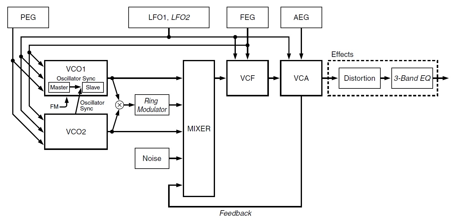
Everyone is familiar with the 100,000 foot view of the Hammond tonewheel generator. A synchronous motor drives an assembly which spins the tonewheels. Each tonewheel has a pick-up that produces a fluctuating sine-like waveform. The waveforms pass through a key switching matrix and drawbars producing a mixed-down, composite organ tone. The tone is sent to the vibrato scanner, reverb, Leslie speaker, etc.
When it comes to modeling, the devil is in the details. I highly recommend reading one of the excellent Hammond tonewheel deep-dives on the Web:
When reading, please think about what is would take to write a mathematical model of this wonderful electro-mechanical contraption! It ain’t as trivial as summing up a bunch of sine waves. 🙂
The tonewheel assembly itself is closer to Charles Babbage’s mechanical Analytical Engine, than it is to an electronic home organ. The twelve (24, really) fundamental pitches are determined by integer gear ratios which approximate equal temperment. The tone wheels themselves have 2, 4, 8, 16, 32, 64, 128, 192 notches, producing subpitches at (near) octave intervals, derived from the fundamental scale pitches.
We know from our own experience that other aspects of the Hammond and Leslie organ system affect the final sound more than the basic tonewheel tones. If I were a developer, I would say, “Memory is cheap,” sample the tonewheels, move on and concentrate on the scanner, vacuum tube distortion, rotary speaker, etc.
Patents
Except, there is the issue of phase relationships when samples are played back. The Hammond tonewheel generator is a mechanical system with fixed relationships between tonewheel positions. This must be taken into account. Naive sample playback moves phase all over the place in an un-Hammond-like manner. Sample playback should be positionally aligned to preserve the fixed relationships present in a real, physical Hammond tonewheel generator.
Dr. K refers to “phase interference:”
“While collecting a range of different pitch waveforms, combining them, and including some non-linear additions, we also had to deal with phase interference between them. It turns out that this interference is not constant, and while balanced over the entire pitch of the instrument, the pitches do shift in subtle and inconsistent ways. … [T]his disordered yet harmonious behavior” is essential and necessary.
I believe that Yamaha have solved this problem by fetching and combining sampled tonewheel waveforms in a different way than everyday AWM2. Here are some patents to consider:
- US Patent 10,388,290 B2 Multifunctional audio signal generation apparatus, August 20, 2019, Inventor: Taro Shirahama, Yamaha.
- Japanese Patent 6360692 B2, Audio signal generation apparatus, July 4, 2018.
Yamaha could be aligning tonewheel waveforms when samples are fetched, thereby eliminating phase errors with respect to Hammond behavior. The sampled waveforms, of course, must also preserve the near-equal temperment of integer Hammond gear ratios. The end result is “Natural, organic harmonies when playing chords.”
I also want to draw attention to:
- European patent application 20214572.8, Rotary speaker emulation — Device, musical instrument, method and program, December 16, 2020, Inventors: Yuji YAMADA and Takashi MORI, Yamaha.
This patent may summarizes Yamaha’s most recent work on rotary speaker emulation although the patent seems to be written as to obfuscate its intent. Yamaha has covered this territory before including:
- US Patent 9,899,016 B2, Time stretching applied to rotary speaker sound, February 20, 2018, Inventors: Masatsugu Okazaki and Taro Shirahama, Yamaha.
Please note the inventors!
Copyright © 2022 Paul J. Drongowski