Back on the streets at home just in time for Korg to drop its newest products. The details are up on the Korg Web site, so there isn’t a need to deep dive the details here.
The Kog Minilogue brings a smile to my face whenever I play it. Since I don’t have an actual need for it, “play it” means “noodle in the store.” However, it is a constant temptation for an impulse purchase.
Thus, I’m pleased to see a new model: the Korg Minilogue XD. Like its updates to the venerable microKorg, Korg are smart to pursue and extend winners. The XD keeps much of the basics intact. The front panel slider is now a joystick — a good change in my opinion. The XD adds a VPM (Variable Phase Modulation)/FM oscillator allowing two op FM voices. Memory is greatly expanded to 500 locations. And two control voltage (CV) inputs.
Expected street price is $650 USD. (The original model streets for about $520.)
Korg also dropped the Volca Modular. If you want to dip into synthesis, here’s your toy, er, tool: eight modules, 50 patch points, 16-step sequencer, “West Coast” style. Yeah, sure, Korg cut cost. The patch points are printed circuit board (PCB) mounted SIL and DIL connectors which take pin-style patch cables instead of 3.5mm plugs. But, wot did you expect for $200 street?
I have to wonder how the Volca Modular would mate to littleBits synth elements?
Finally, Korg revealed the Volca Drum digital percussion synthesizer. Bang on the drum all day with a 16-step sequencer and MIDI IN. Expected street price is $170 USD. Both Volcas will ship in early 2019.
Piano storm
It’s just rainin’ pianos up in here!
Casio have been teasing what could be a new stage piano. [I don’t do teasers any more.] Casio also have new CDP models: CDP-S100 and CDP-S350. “CDP” apparently means “Compact Digital Piano.” Both pianos feature new piano samples and the new Casio Scaled Hammer Action II Keyboard. The CDP-S100 and CDP-S350 have estimated street prices of $500 and $675, respectively. [I’m awaiting USA pricing.]
The CDP-S100 is aimed squarely at the cost conscious and portable Yamaha Piaggero series. The S100 has 64-note polyphony, ten voices, reverb/chorus, two built-in speakers, and battery power (six AA batteries). It weighs 10.5kg (23.1 pounds) and is quite slender. The speakers are front-firing a la the Studiologic NUMA Compact 2x.
The CDP-S350 takes a page from the Korg Havian playbook and the Yamaha DGX series by incorporating arranger keyboard features with a high quality piano. Quick specs include 64 note polyphony, 700 voices, 10 user songs, 200 rhythms (AKA “styles”), auto-harmonization, 100 arpeggios, and battery operation. Weight is 10.9kg (24 pounds). The S350 also employs built-in, front-firing speakers.
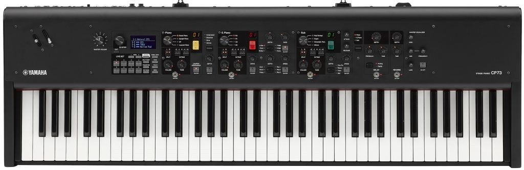
Yamaha are announcing the new CP73 and CP88 stage pianos, both clearly positioned to compete with Nord on-stage. The CP88 features Natural Wood Graded Hammer (NW-GH) action while the CP73 has 73 equally-weighted keys. Both axes have Yamaha’s best piano sounds: Yamaha CFX and Bösendorfer Imperial grands. Yamaha also got the message from pros: Seamless Sound Switching and XLR balanced outputs.
Taking a close look at the front panel, the new CPs offer three sound sections: acoustic piano, electric piano and “sub” from which one builds splits and layers. There are LIVE SET buttons to quickly change between configurations. Pitch bend and modulation control are through two levers located in the upper left corner of the work surface.
Like Nord, Yamaha are offering “content upgrades.” The first available sound upgrades include Rhodes (“1967 tine piano), Wurli (“reed piano”) and Yamaha C7 “studio” grand piano.
Expect $2,499.99 USD for the CP88 and $1,999.99 for the CP73. I find it interesting that the press release is out of Rellingen, Germany — home of the Genos™ and other Yamaha arranger products. Probably not significant.
Copyright © 2019 Paul J. Drongowski