Add SPI to littleBits Arduino 2

Music makers working with littleBits Arduino will almost certainly want to add a high(er) resolution digital-to-analog converter (DAC) to their Arduino. Part 1 shows how to add an ICSP header to your littleBits Arduino module. The ICSP header is where you find the SPI signals — MISO, MOSI, and SCK — along with Vcc (+5 Volts) and ground. The ICSP header pin layout is:

         GND ---O  O--- RESET
    MOSI/D16 ---O  O--- SCK/D15
         VCC ---O  O--- MISO/D14

This is the layout when viewing the top of the Arduino module with the USB connector at the top (i.e., away from you, “north” on a map).

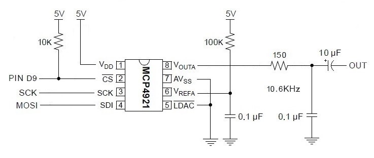
Now let’s take a look at a simple circuit using the Microchips MCP4921 12-bit DAC. (Click on images to get higher resolution.)
spi_dac_schematic

Three signals control the DAC: Slave Select (SS/Pin D9), Master Out Slave In (MOSI) and Serial Clock (SCK). Data is sent to the DAC through SPI’s bit serial protocol. First, SS is driven LOW, then 16 bits are sent one at a time to the DAC. SCK synchronizes the data bits sent via MOSI. The first byte consists of a 4-bit “command” and the top 4 bits of the 12-bit value to be converted. The second byte is the lower 8 bits of the value to be converted. After sending 16 bits, the SPI master drives SS HIGH. If you’re curious about all of the signaling details, please see the MCP4921 data sheet.

The rest of the DAC circuit consists of a voltage reference for the converter and a post-conversion (reconstruction) filter. The filter is a simple, one stage passive low pass filter with a 10,600Hz corner frequency.

I built the DAC circuit on a small solderless breadboard. Here’s the layout.
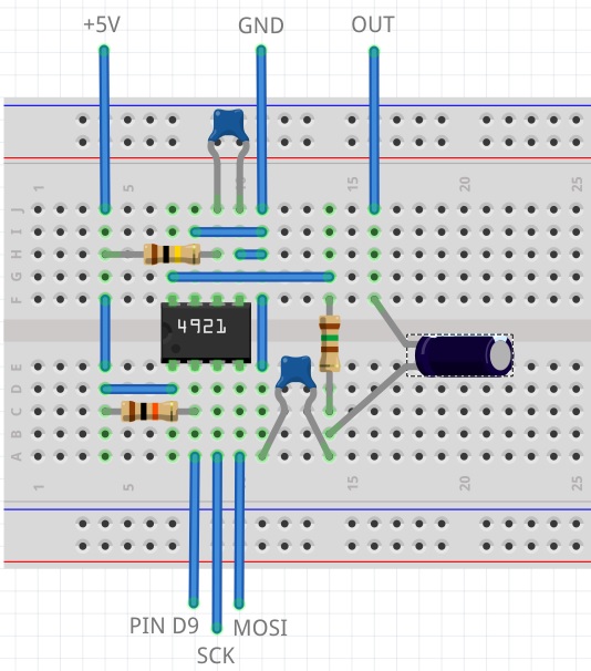
spi_dac_breadboard

I connected MOSI, SCK, +5V and ground to the appropriate ICSP pins on the Arduino module. Slave Select is sourced by Arduino pin D9. I connected a littleBits Proto module to D9 and routed the input signal to the breadboard. If you want to postprocess the DAC’s audio output with littleBits modules, then route the DAC output to the Proto module’s output snap. Be sure to remove the shorting block (jumper) between the middle two pins on the Proto module. This approach provides power and ground to the audio postprocessing modules connected to the output snap of the Proto module — an important side-benefit.

The choice of pin D9 for Slave Select was the beginning of a long, hard journey in debugging. To make a long story short, pins D5 and D9 are buffered and the output buffer introduces additional delay on the Slave Select signal. The delay is long enough such that the DAC does not see a low Slave Select signal before data bits start arriving.

Here’s the code that writes the DAC:

#define NOP asm volatile ("nop\n\t")
void busyWait(uint8_t count) { 
  for(uint8_t i = count; i > 0 ; i--) { NOP ; } 
}

void writeDac(int16_t dacValue) {
  byte data ;
  SPI.beginTransaction(SPISettings(20000000,MSBFIRST,SPI_MODE0)); 
  digitalWrite(SlaveSelect, LOW) ;
  busyWait(25) ;
  data = highByte(dacValue) ;
  data = 0x0F & data ;
  data = 0x30 | data ;
  SPI.transfer(data) ;
  data = lowByte(dacValue) ;
  SPI.transfer(data) ;
  digitalWrite(SlaveSelect, HIGH) ;
  SPI.endTransaction() ;
}

The busy wait effectively stops the sketch for a little while after driving Slave Select LOW. This gives the Slave Select more time to reach the DAC before the sketch transfers the first data byte to the DAC. If you use an unbuffered pin like D1, you don’t need the busy wait.

It took a long time to eliminate all of the other possible issues that could have caused a failure: bad solder joints, wiring mistakes, etc. Fortunately, I have a similar DAC — the MidiVox — which works correctly. I also tested the hardware with Arduino UNO where all digital pins are unbuffered. It was frustrating to get everything working with the UNO, but not the littleBits Arduino module! Persistence wins the day.

In closing, I want to warn developers who interface high speed logic to littleBits Arduino. Beware of the delay through those buffered outputs! The delay may be long enough to throw off critical timing.

Add SPI to the littleBits Arduino

As Moe Szyslak might say, “He ain’t pretty no more!”

Last time through, I mentioned that I wanted to add a SPI digital-to-analog converter (DAC) to the littleBits Arduino module. The Microchips MCP4921 is a good candidate. It is a 12-bit DAC which communicates via the Small Peripheral Interface (SPI) bus or “SPI.”

The littleBits Arduino module is essentially an Arduino Leonardo. As such, its SPI port is available through the module’s ICSP pads. (“ICSP” stands for “in-circuit serial programming,” by the way.) The ICSP pads are the group of pads (two rows of three pads) between the D5 and D9 bitSnaps.

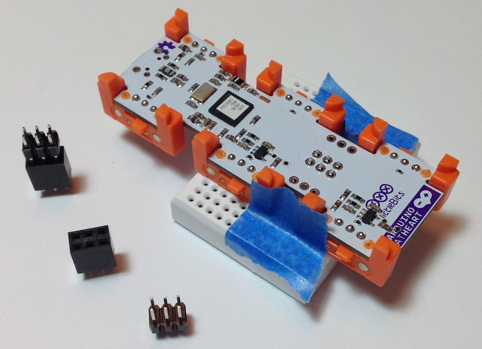
I soldered a 2×3 vertical pin header to the ICSP pads using a very simple jig. The image below is a “before and after” picture. (Click images for higher resolution.) The jig is a solderless breadboard that holds the header in place. I pushed the header into the breadboard just enough to hold the header and then placed the Arduino module over the header and pressed down. The idea is to get the black base of the header in contact and properly aligned with the module printed circuit board (PCB). The blue strips of masking (painter’s) tape keep the assembly together. The “after” part of the image shows the module with the header soldered in place.

icsp_solder_after

The jig really makes the soldering job easy. I have used other methods like trying to tape the header pins in place, but this approach was a piece of cake and frustration free.

The image below shows the header, module and jig just before soldering. The picture also shows the 2×3 vertical pin header and a compatible 2×3 female header block. You could install the female header block instead. I went with the male header because most ICSP cables expect a male header on the PCB to be programmed.

icsp_solder_jig

I ordered the parts from Mouser Electronics. Mouser and Jameco are my usual “go to” sources for components and tools. Here are the part numbers:

  • Harwin M20-9980346 03+03 DIL VERTICAL male header 2.54mm
  • Harwin M20-7830342 03+03 DIL VERTICAL female header 2.54mm
  • BPS BB170-WH White 170 point solderless breadboard
  • BPS ZW-MF-20 ZIPWIRE Female-Male 20cm
  • BPS ZW-MM-20 ZIPWIRE Male-Male 20cm

The “2.54mm” refers to the pin spacing (AKA “0.1 inch”). The female header is $1.19 and the male header is $.24. Buy at least ten of each and the price goes down a little. The contacts are tin; gold is a little more expensive.

I plan to make (eventually) little PCB “hats” using the female header blocks. The idea is to build a small, single-purpose circuit that plug onto the ICSP header or littleBits Proto module header like a hat. This approach would eliminate point-to-point connections using jumper wires. I may experiment with this approach once I get the basic DAC circuit ironed out and tested.

I really like Busboard Prototype System (BPS) products. BPS has the most useful prototyping board patterns. They also have these nifty ZIPWIRE ribbon cables. The wires terminate with individual male pins or female receptacles. Let’s say you need to make six connections from the ICSP header to a solderless breadboard. Then tear off a group of six wires and associated terminations. Push the receptacles onto the male header and push the pins into the solderless breadboard. The individual wires are color-coded in order to make the correct point-to-point connections at both ends. I’ll use ZIPWIRE to connect the Arduino SPI port (ICSP) to a solderless breadboard with the SPI DAC circuit.

If you have a littleBits Arduino module and want to make the most of it, it’s time to break out the soldering iron. Best of luck!

Inside Reface DX and Reface CS

With so much to do and learn, it’s been a long while since I’ve taken a peek below the hood of an electronic musical instrument.

Yamaha caught the world by surprise with its Reface series of portable keyboards. So far, there are four models in the series: Reface YC (organ), Reface CP (electric piano), Reface CS (analog modeling synthesizer), and Reface DX (4-op FM synthesizer).

Before I get to the DX and CS, here’s a few thoughts about the YC and CP. According to Yamaha specifications, the Reface YC tone generation engine is “AWM (Organ Flutes)”. This suggests to me that the YC uses a standard AWM tone generation integrated circuit (IC) like the SWP70. Hammond-like “Organ Flutes” have been part of the mid- and upper-tier arranger workstations like Tyros for a very long time. Thus, I suspect that the YC implementation is an updated implementation of the arranger technology.

The Reface CP tone generation engine is specified as “SCM + AWM2”. SCM or “Spectral Component Modeling” is the modeling technique first employed in the flagship CP-1 stage piano. SCM and AWM2 are also used in the CP-4 and CP-40 models. The CP-1 uses three tried-and-true SWP51L tone generation ICs: master, slave and effects. The master and slave generate the base piano tones and the two ICs share the same WAVE ROM. Total WAVE ROM size is 1024Mbits or 128MBytes (organized as 16-bit words) which is a ridiculously small amount of memory for a top quality piano. Such is the power of SCM!

The CP-1’s samples are stored in two Lapis Semiconductor MR26V51252R devices (32M by 16-bit words each). The processor is a Yamaha SWX02 (SH-2A CPU core operating at 135.4752MHz). There’s not much to the CP-1 user interface, so a relatively light-weight, low-cost processor is enough for the job. The SWP51Ls handle all of the heavy computation.

Thus, the Reface YC and Reface CP are relatively uninteresting from a technologist’s point of view. The YC and CP use proven technology from other Yamaha products. That leaves the Reface CS and Reface DX.

Although the CS and DX implement two different tone generation techniques — analog physical modeling vs. frequency modulation (FM) — they are fraternal twins at the hardware level. They share much of the same base hardware design with a few variations to handle their unique user interface requirements.

The CS and DX both use a Fujitsu MB9AF141LAPMC1 processor to handle key and panel scanning. Here’s a quick summary of its characteristics:

    CPU                 Cortex-M3
    CPU Frequency       40MHz

    On-chip flash memory   Main area   64KBytes
    On-chip flash memory   Work area   32KBytes
    On-chip SRAM           SRAM0        8KBytes
    On-chip SRAM           SRAM1        8KBytes

    Peripheral interfaces:
        DMAC            8 channel
        Serial I/F      8 channel
        Base timer      8 channel
        Dual timer      1
        Realtime clock  1
        Watch counter   1
        12-bit A/D      12 channel

This processor is a good choice for embedded control applications where low power and low cost are important. To my knowledge, this is the first product line using an ARM embedded microcontroller.

The Reface CS and Reface DX both use the proprietary Yamaha SSP2 (uPD800500F1-011-KN9-A) for tone generation. The SSP2 is Yamaha’s designated hitter for DSP tasks and is incorporated into many products. The SSP2 has an SH-2A CPU core operating at an internal clock speed of 135.4752MHz. The SSP2 has its own ADC, GPIO, UART, USB and serial audio interfaces. The SSP2 UART handles 5-pin MIDI communications. The SSP2 USB interface handles external USB communications.

The SSP2 has two memory interfaces:

  • DSP RAM: Connecting to 8MBytes of DSP SDRAM.
  • CPU bus: Connecting to 8MBytes of program ROM and 16MBytes of SDRAM.

Memory sizes and devices are the same in both products.

The AUX IN and audio out hardware design is also the same across the two products:

  • PCM1803ADBR ADC: AUX IN analog-to-digital converstion
  • AK4396: Digital-to-analog conversion for OUTPUT L/R and PHONES OUT
  • YDA176 D-Amp: DAC and amplification for internal speakers

This shouldn’t be any surprise. All of the Reface series products ahare the same external jack, power and key switch boards.

Digital audio is transfered serially between the SSP2, the ADC, the DAC and the digital amplifier. The SSP2 generates the master clock (MCLK) and bit clock (BCLK) to synchronize data transfers. MCLK and BCLK are derived from the SSP2 clock, in case you’re wondering about those odd-looking CPU clock frequencies. MCLK is 256*fs and BCLK is 64*fs, where fs is the sampling frequency, 44.1KHz. MCLK operates the AK4396’s digital interpolation filter and delta signal modulator. Data format is I2S and is probably 24-bit as it is in workstation products.

Aside from the other front panel controls, the Reface DX has two major additions: Capacitive sensors for the front panel touch strips and the LCD panel display. The printed circuit board positions for the LCD interface are not populated (i.e., no mount) in the Reface CS as it has no LCD display.

There you have it — two more examples of solid and conservative Yamaha hardware design.

Now, you may find the SSP2 to be incredibly boring. It is, however, a good choice for a low-cost, compact product. The Reface CS and DX need a metal shield over the SSP2, perhaps to control RF emissions, perhaps to radiate heat, or maybe both purposes together. Low power is a vital concern throughout the Reface series due to battery power concerns.

I’m a little hesitant to draw any inferences about future products. The Yamaha Montage supports 128 note, 8 operator FM polyphony. The Reface DX provides a relatively meager 8 note, 4 operator FM polyphony. Thus, there must be considerable hardware resources at work in the Montage. Well-worth the price, one hopes! And speaking of hopes, many people would like an analog modeling extension to the Montage. That would depend, of course, on the availability of spare computational horsepower.

Copyright © 2016 Paul J. Drongowski

Audio via Arduino 16-bit PWM

Most of my project postings described a project in a completed state with full code, electronic design, etc. This post covers some things that I’ve learned during my current open investigation. Think of it as a “breather” before the next push.

Audio folks who get into Arduino often ask, “Gee, why not use PWM to produce audio — a poor man’s DAC?” 8-bit PWM resolution is the default supported PWM mode. The resolution and the bandwidth is not sufficient to support decent audio. First off, the PWM stream must be converted to an analog signal using a low pass filter, with a typical corner frequency of 150Hz or so. The default mode is really intended to control servos and such.

The littleBits Arduino is a good example implementation. The PWM outputs have a filter to convert the PWM bit stream to an analog voltage. The filter can be switched off if you want access to the raw digital data or PWM bit stream, making the Arduino’s outputs quite versatile. Depending upon your perspective, the littleBits filter is quite good for low bandwidth applications, not so good for audio. In fairness, littleBits never claim to support audio via their PCM hardware.

The PWM signals are generated by the Arduino’s timer/counter hardware. The Arduino UNO and Leonardo, for example, have three timers which can generate a PWM signal:

  1. TIMER0: 8-bit PWM, pins D5 and D6, delay()
  2. TIMER1: 8-bit and 16-bit PWM, pins D9 and D10
  3. TIMER2: 8-bit PWM, pins D3 and D11, tone()

Timers 0 and 2 are used by the Arduino delay() and tone() functions, respectively. So, you cannot use these functions and expect to generate PWM at the same time.

All appears lost for audio until one discovers TIMER1’s 16-bit PWM mode. I decided to try 16-bit PWM on the littleBits Arduino with the hope that the pre-existing filter would successfully convert the PWM bit stream to audio.

Long story short, the littleBits filter is too good at its job! The filter looks to be an active Sallen-Key low-pass filter with a corner frequency of 49 Hertz. Through much of my experimentation, I sent percussive samples (e.g., open high hat and cymbal) through TIMER1’s PWM channel. The littleBits filter neatly removes all of the high frequency signal resulting in a low frequency thud like a kick drum or low tom.

So, instead, I decided to switch off the littleBits filter and convert the PWM bit stream through a passive, low-pass filter of my own. The following table summarizes the RC components and filter characteristics that I tried:

    Resistor                  Capacitor  Corner frequency
    ------------------------  ---------  ----------------
    100 (Brown Black Brown)     0.1uF     15915 Hertz
  * 150 (Brown Green Brown)     0.1uF     10610 Hertz *
    220 (Red Red Brown)         0.1uF      7234 Hertz
    330 (Orange Orange Brown)   0.1uF      4822 Hertz
     1K (Brown Black Red)       0.1uF      1592 Hertz
    10K (Brown Black Orange)    0.1uF       159 Hertz

I held the capacitance constant in order to find the best resistance for the filter. The 150 ohm resistor worked best. It produced the best quality audio with the least artifacts although I still need to tame a high pitched whine. I may have to add another filter stage (a so-called “2-pole” or “second order” filter). The corner frequency is roughly the Nyquist frequency — no accident.

At this point, it probably appears that it was a smooth ride from start to finish. Nothing could be further from the truth! Here are a few “learning moments” from the journey.

First, be sure your power is clean. I started out with a switching power supply that successfully drives Arduinos big and small. The output signal had a raunchy buzz that I could not extinguish with the filter. Turns out, the switching supply is noisier than heck and the noise gets into the audio. I replaced the switching power supply with a clunky, old, heavy Yamaha PA-3B and the raunchy buzz went away.

Next, don’t trust code that you find on the Web. I started with timer configuration code from what appears to be a reputable site. After hours of frustration, I read up on the TIMER1 hardware and rewrote the code. The original code simply could not have worked as it set non-existent bits in the timer control registers! Here is my timer configuration code and interrupt service routine (ISR).

    //
    // TIMER1 PWM. Single PWM, phase correct, 22050KHz.
    // PWM_FREQ = 16,000,000 / 22,050 =  726 = 0x2D5
    // PWM_FREQ = 16,000,000 / 11,025 = 1451 = 0x5AB
    //
    #define PWM_FREQ   363

    void PwmSetup() {
      // Clear OC1 on compare match, 8-bit PWM
      //TCCR1A = _BV(COM1A1) | _BV(WGM10) ;
      TCCR1A = _BV(COM1A1) ;
      // PWM TOP is OCR1A,  No prescaler
      TCCR1B = _BV(WGM13) | _BV(CS10) ;
      // Generate interrupt on input capture
      TIMSK1 = _BV(ICIE1) ;
      // Set input capture register to sampling frequency
      ICR1H = (PWM_FREQ >> 8) ;
      ICR1L = (PWM_FREQ & 0xff) ;
      // Turn on the output pin D9
      DDRB |= _BV(5) ;
      sei() ;
    }

    //
    // Interrupt service routine (ISR)
    //
    ISR(TIMER1_CAPT_vect) {
      if (sampleCount > 0) {
        sample = (int8_t)pgm_read_byte_near(sampleArray+sampleIndex) ;
        dacValue = sample  ;

         // Output through OC1A
        dacValue += 127 ;
        OCR1AH = (uint8_t) (dacValue >> 8) & 0xFF ;
        OCR1AL = (uint8_t) dacValue & 0xFF ;
  
        sampleCount-- ;
        sampleIndex++ ;
        TXLED1 ;
      } else {
        TXLED0 ;
      }
    }

TIMER1 implements a bit capture capability along with the PWM generation stuff. The bit capture counter is configured to generate sampling interrupts, i.e., the PWM side is fed at a 20,050 samples per second rate. The output compare register controls generation of the PWM signal. It’s the place where a sample is fed.

If you go to use this code, the samples are stored in program memory (PROGMEM) and are 22,050Hz, 8-bit, mono. The sampleArray contains the samples. The two global variables sampleCount and sampleIndex control sample selection from the array. The sampleCount is preloaded with the number of samples in the array by the loop() function. The TXLED macros only work on Leonardo and indicate when samples are being played or not. These macros could be removed in production code.

Third, get the sampling frequency right. Corollary: Use a pitched sound like a sine wave of known frequency to make sure that the sampling frequency is correctly configured. The PWM generation in this design is configured to be phase correct, which halves the frequency. High frequency content becomes even more “thud-like” at a lower frequency making it difficult to sort out other configuration and filter issues. I got around this barrier by feeding a digitized 440 Hertz sine wave into the PWM conversion. When the tone sounded an octave lower than expected, I realized that I needed to double the configured sampling frequency.

Trust me, the road was not straight and smooth. I didn’t make progress on filter design until these issues were resolved. Science and engineering ain’t so simple, but the challenge is both fun and rewarding.

Update 18 July 2016: Take a sneak peek at the source code for the Arduino Beat Box (TR-808 lo-fi drum machine). The source code contains the final TIMER1 set-up and interrupt service routines.

Connect a MIDI shield to littleBits Arduino

My do-it-yourself MIDI interface for littleBits Arduino probably isn’t for everyone. Constructing the DIY interface requires circuit layout skills and not everyone wants to whip up a board from scratch and a schematic.

Fortunately, there are a couple of alternatives: the Olimex SHIELD-MIDI and the Sparkfun MIDI Shield. I don’t have any direct experience with the Olimex, but I have built and used the Sparkfun MIDI Shield (Sparkfun product number DEV-12898) and the now retired MIDI Breakout Board. The Olimex SHIELD-MIDI is very similar to the retired breakout board. In this post, I show how to hookup the Sparkfun MIDI Breakout Board to the littleBits Arduino. The wiring is the same for the Sparkfun MIDI Shield. That’s the neat thing about the standard Arduino form factor.

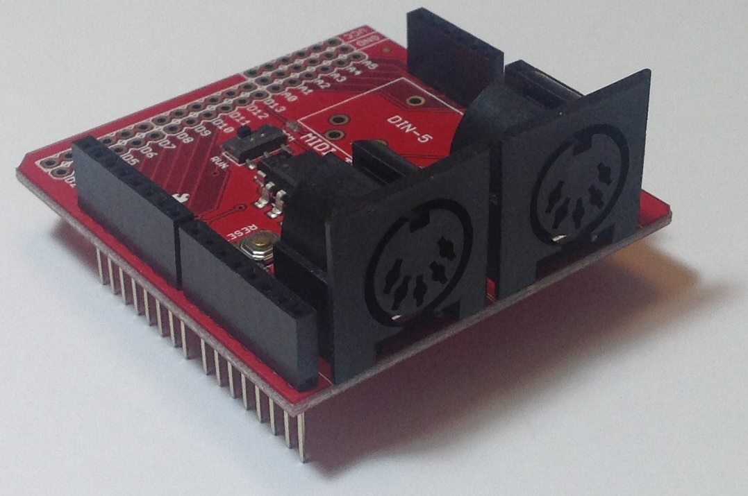
I would demonstrate with a Sparkfun MIDI Shield, but all of my MIDI Shields are customized in some way! The Sparkfun MIDI Breakout Board is basically the same as the MIDI Shield except that it doesn’t have the potentiometers and tactile switches. The image below is a picture of the Sparkfun MIDI Breakout board. (Click on the image to get higher resolution.) The two 5-pin DIN connectors are the MIDI IN and MIDI OUT ports. The long pins extending below the breakout board plug into a standard Arduino like an UNO or Leonardo.

sparkfun_midi_breakout

The Sparkfun MIDI breakout board (or shield) arrives as a kit, so you still need to do some assembly. Sparkfun has already installed and soldered the tough stuff like the optoisolator, resistors and so forth. The MIDI Shield is a good beginner’s kit because the components to be installed are large and easy to solder. If you skip installing the potentiometers and tactile switches, the job is even easier!

You might want to add an Arduino Stackable Header Kit (PRT-10007), however. With the header kit, you’ll be able to interconnect using standard jumper wires. Once the headers are installed, no further soldering is necessary. Just plug the jumpers into the headers and play. Mistakes are easier to correct with jumper wires, too.

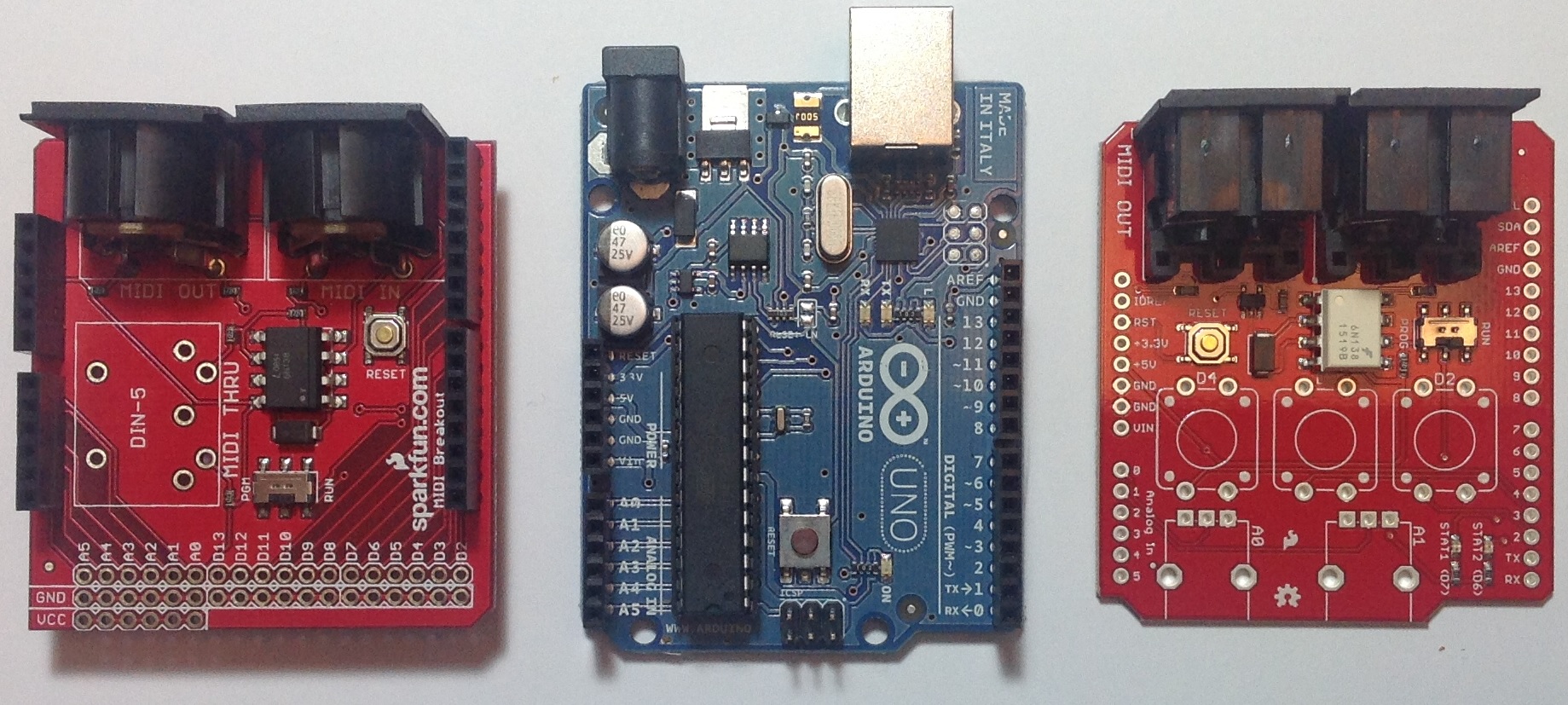
Here is the top-view of the MIDI breakout board, an Arduino UNO processor board and a Sparkfun MIDI Shield. Click the image for higher resolution. You’ll want to take a closer look at the three boards in order to see the signal name associated with each header pin. (You can really zoom in if you download the image and load it into a paint program.)

midi_bob_uno_shield

The breakout board has a position for a MIDI THRU connector. This position is empty as the headers would block the opening of the 5-pin DIN connector. We don’t need the THRU port, so this isn’t a deal-breaker.

As I mentioned before, the long pins extending below the headers normally plug into a standard Arduino processor board (e.g., UNO or Leonardo). Each header pin effectively mirrors the electrical signals of the underlying Arduino board. So, in order to hookup to the littleBits Arduino, we just need to connect the appropriate Arduino board signals to the corresponding bitSnaps on the littleBits Arduino. That’s why you really want to zoom in and see the signal names. The board labels tell us where to plug in jumper wires.

We need four connections:

  • +5 Volts: Red wire
  • Ground: Black wire
  • RX (digital pin D0): Yellow wire
  • TX (digital pin D1): Blue wire

Our old high school shop teacher would yell at us if we didn’t use the right color wire for power, ground, etc. I will say, different wire colors make it easier to check and debug wiring!

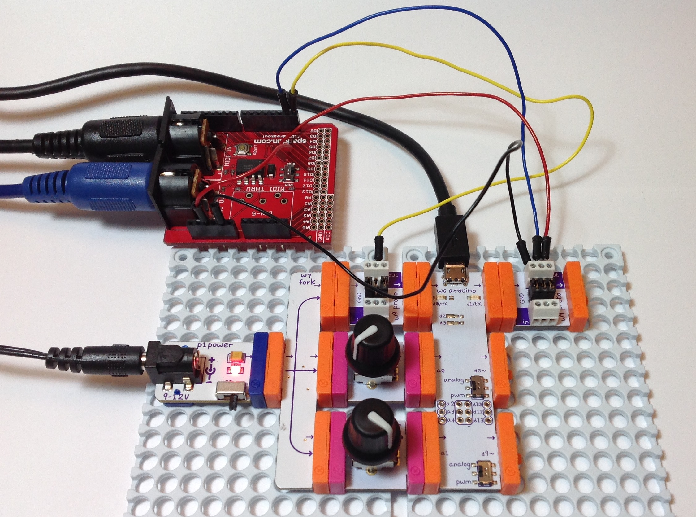
So, how do we make connections to the littleBits Arduino? I used two littleBits proto modules: one proto module for the MIDI input side and one proto module for the MIDI output side. The other end of each jumper terminates in a screw connector on a proto module. Please see the image below. (Click to enlarge.)

sparkfun_midi_littlebits_arduino

RX is connected to RX, TX to TX, +5 Volts to +5 Volts, and Ground to Ground. The MIDI IN goes to the Arduino’s RX pin and the the Arduino’s TX pin goes to MIDI OUT.

You must configure the jumpers on each proto module. The MIDI OUT side is easy; just leave all three jumpers installed. One the MIDI IN side, remove the center jumper on the proto module. This breaks the connection from the proto board input to the proto board output. You must remove this jumper or the input signal will interfere with the incoming MIDI data.

Once all of the connections are made, you’ll need sketches to test the connections. Please see my article about testing an Arduino MIDI interface. The article describes a simple testing process. The article also has links to a simple MIDI sequencer sketch and the source code for a MIDI IN to MIDI OUT sketch. The MIDI sequencer sketch checks the MIDI OUT side. Once you know the MIDI OUT is good, then the MIDI IN to MIDI OUT sketch checks the MIDI IN side. (The sketch echoes MIDI IN to MIDI OUT.)

That’s it! You should now have your 5-pin MIDI equipment talking with the littleBits Arduino. If this project has bolstered your confidence with hardware — and I hope that it has — then please take a look at the DIY 5-pin MIDI interface project.

littleBits Arduino MIDI interface

I thought, “When it comes time to test the 5-pin MIDI interface with the littleBits Arduino, just hook it up. Download the sketches. Take a victory lap.”

Instead, I got an “opportunity” to discover and learn. Not so fast, but not so bad, either.

Please recall that a few posts ago I described the design of a 5-pin MIDI interface for Arduino. The MIDI IN part of the interface attaches to the Arduino RX pin (pin D0) and the MIDI OUT part connects to the TX pin (pin D1). I tested the 5-pin MIDI interface with an Arduino UNO board using the simple MIDI sequencer sketch and a sketch to echo MIDI IN to MIDI OUT. My original plan was to connect the 5-pin MIDI interface to the littleBits Arduino via two protoboards, then run the sketches, again, for testing.

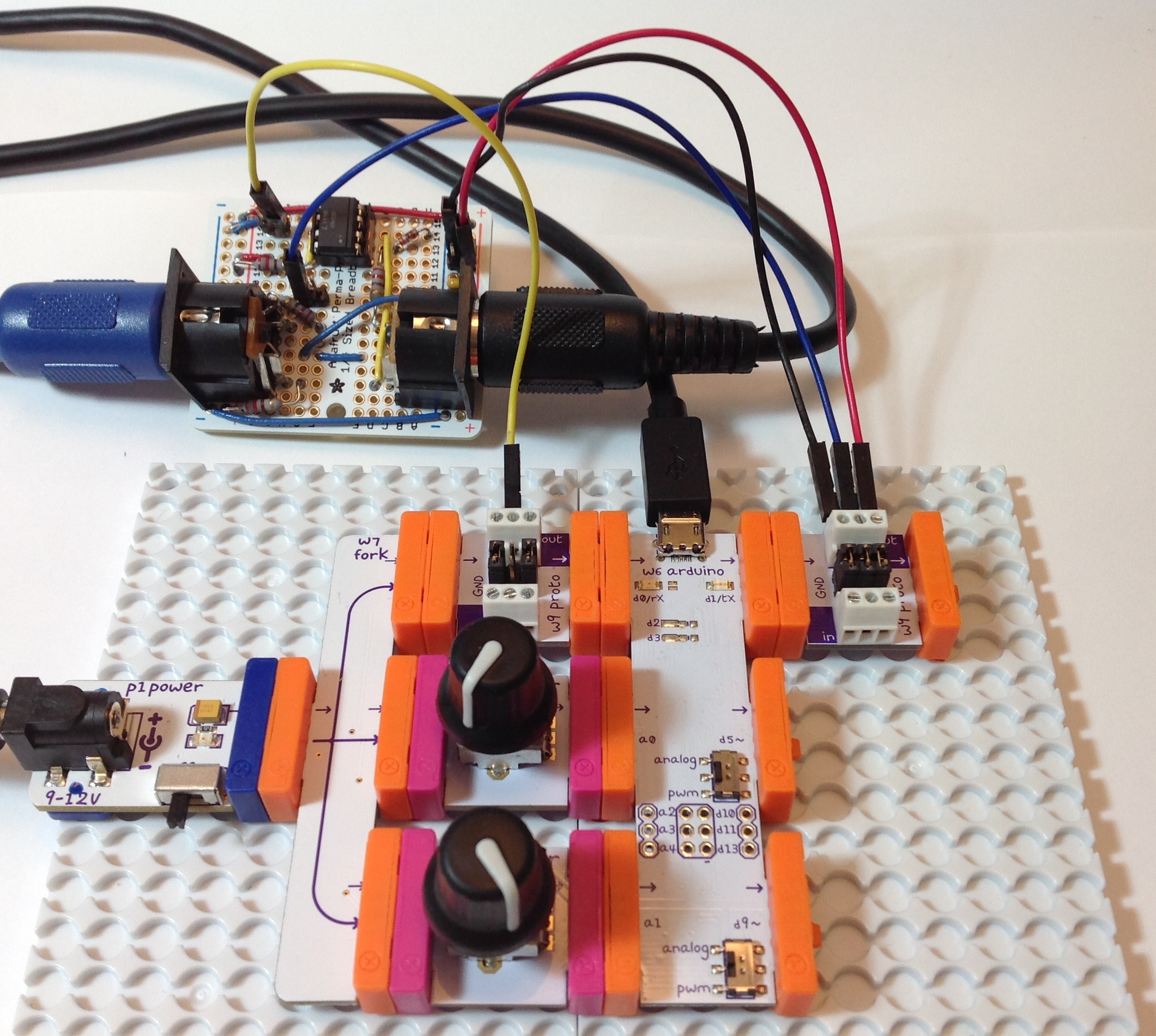
First, the hook up. The image below shows the littleBits hardware. (Click the image for full resolution.) The Arduino is “at the heart” and communicates with a PC through the USB port. The littleBits proto module directly to the left of the USB port brings the logic-level MIDI IN signal to the Arduino RX pin. The proto module directly to the right of the USB port sends the Arduino TX signal to the MIDI OUT circuit. The signals to and from the 5-pin MIDI interface board are:

  • Yellow wire: Logic-level MIDI IN
  • Blue wire: Logic-level MIDI OUT
  • Red wire: +5 Volts (Vcc)
  • Black wire: Ground

MIDI is a serial communication standard operating at a rate of 31,250 bits per second. RX and TX are the Arduino’s digital serial receive and transmit pins, respectively.

littlebits_arduino_midi_interface

So far, so good. There are a few extra details to consider. The positive supply voltage (+5 Volts) and ground are distributed throughout the whole interface board. Only one set of power supply connections are needed to power the interface board. I attached the power supply connections to the proto module handing the MIDI OUT. Next, the proto module jumpers are configured a little bit differently on the MIDI IN and MIDI OUT sides. Having all three jumpers in place, the MIDI OUT proto module passes all signals: Vcc, ground and the data signal arriving from TX. The MIDI IN proto module only passes Vcc and ground. It does not pass the signal from its input bitSnap. The output from the proto module is generated by the signal coming from the 5-pin MIDI interface board (i.e., the yellow wire). This signal is send to the RX pin.

Adhering to my original test plan, I downloaded the simple MIDI sequencer sketch. This sketch tests the MIDI OUT circuit by sending MIDI note on and note off messages. I attached the MIDI OUT connector to a MIDI tone module, flipped the power switch, and no sound. MIDI data was not being sent to the MIDI tone module. After much wailing, gnashing of teeth and browsing, I remembered that the Arduino Leonardo board has two serial ports, not one port like the UNO. One serial interface handles RX/TX and another serial interface handles USB communications.

The littleBits Arduino is a Leonardo board. Was the MIDI data being sent to the USB port? I turned on the Serial Monitor in the IDE. Yep, the Serial Monitor was showing jibberish arriving from the Arduino. I expected jibberish because the bit rate was all wrong, but nonetheless, observations confirmed that MIDI data was going to the wrong port (USB instead of TX).

The Arduino IDE exposes two serial ports for a Leonardo board:

  • Serial” refers to the virtual serial port over USB.
  • Serial1” refers to the serial port through RX/TX.

Originally, I wrote and compiled the MIDI sequencer sketch for an Arduino UNO board. The calls to write() refered to Serial. That’s fine on the UNO because the UNO uses the same serial port for RX/TX and USB communication and everything works. On Leonardo (littleBits), however, the sketch refers to the USB serial port, not RX/TX as I had intended.

I solved the problem with conditional compilation. Here is the new code for the function MidiSend() in the MIDI sequencer sketch:

//
// Send a short, 3-byte MIDI message
//
void MidiSend(byte cmd, byte data1, byte data2)
{
#ifdef LEONARDO
  Serial1.write(cmd | CHANNEL) ;
  Serial1.write(data1) ; 
  Serial1.write(data2) ; 
#else
  Serial.write(cmd | CHANNEL) ;
  Serial.write(data1) ; 
  Serial.write(data2) ; 
#endif
}

The symbol “LEONARDO” determines the code to be compiled into the sketch. If LEONARDO is defined then the sketch sends MIDI bytes to Serial1. If LEONARDO is not defined, then the sketch sends MIDI bytes to Serial. I also needed to fix up the code in setup():

#ifdef LEONARDO
  Serial1.begin(31250) ;
#else
  Serial.begin(31250) ;
#endif

After making these changes and defining LEONARDO at the beginning of the sketch:

#define LEONARDO 1

I compiled and uploaded the sketch. Voila! I heard music from the tone module! MIDI data was now being sent to the appropriate Arduino serial port (TX).

Along the way, I also learned some useful information about the RX and TX LEDs. The RX and TX LEDs flash when data is transfered through the USB port. They do not flash when data is sent through the RX/TX pins. If you want to flash the LEDs yourself, then use the following macros:

    RXLED0;
    RXLED1;
    TXLED0;
    TXLED1;

These macros are a feature of the Leonard board and are not recognized on UNO.

Two separate, independent serial ports has its advantages. First, it isn’t necessary to disconnect the 5-pin MIDI interface board when uploading a sketch. With only one serial port on UNO, TX/RX and USB communication cannot peacefully co-exist. On Leonardo (littleBits), they do peacefully co-exist and you can use the virtual serial port over USB (i.e., Serial Monitor) to trace program execution and print debug messages while using RX/TX for MIDI communication. Finally, if we don’t ever touch Serial1, we should be able to configure D0 and D1 as regular Arduino digital input and output pins (respectively).

By now, you realize that I had to modify the sketch that echoes MIDI IN to MIDI OUT, too. Instead of conditional compilation, this sketches defines a symbolic constant, “SERIALPORT,” which expands to the name of the serial port to be read and written. Full disclosure: I did not test the MIDI library version on littleBits (Leonardo).

//
// Send MIDI IN to MIDI OUT (THRU)
//

// Author:  P.J. Drongowski
// Date:    6 June 2016
// Version: 1.1
//
// Copyright (c) 2016 Paul J. Drongowski
// Permission granted to use, copy and distribute

// Uncomment the following line to use the Arduino 
// MIDI library instead of serial read() and Write().
// #define USE_MIDI_LIBRARY 1
// This has not been tested/debugged on LEONARDO!

// Define the symbol SERIALPORT to select the appropriate
// serial port:
//    Serial    UNO
//    Serial1   LEONARDO/littleBits
#define SERIALPORT Serial1


#ifdef USE_MIDI_LIBRARY

#include <MIDI.h>
MIDI_CREATE_DEFAULT_INSTANCE() ;

void setup() {
  MIDI.begin(MIDI_CHANNEL_OMNI) ;
}

void loop() {
  if (MIDI.read())
  {
    MIDI.send(MIDI.getType(),
              MIDI.getData1(),
              MIDI.getData2(),
              MIDI.getChannel());
  }
}

#else

int midiByte = 0 ;

void setup() {
  // Initialize the serial port for MIDI
  SERIALPORT.begin(31250) ;
}

void loop() {
  if (SERIALPORT.available() > 0) {
    midiByte = SERIALPORT.read() ;
    SERIALPORT.write(midiByte) ;
  }
}
#endif

MIDI sequencer: Testing your MIDI interface

Now that you’ve assembled the MIDI interface for your Arduino, it’s time to try it out. That means you need a few basic sketches to test and debug the interface.

First, a philosophical word or two. Testing is one of the most neglected and least emphasized topics in engineering. Other than careful design, assembly and coding, nothing else is as important to the success of a project as testing. In practice, you should be thinking about testing while you design, code, layout and solder. Without getting too computer science-y, it all comes down to controllability and observability — the ability to apply a stimulus (test input) and the ability to measure and assess a response (expected vs. actual test output).

Take the case of our MIDI interface. There are two major subsystems: the MIDI IN circuit and the MIDI OUT circuit. We must drive the MIDI IN circuit with a keyboard (or some other device) that sends MIDI to the 5-pin MIDI IN connector. The Arduino reads the logic level bit-stream through its RX pin (pin D0). The messages in the bit-stream need to conform to the MIDI message standard. On the MIDI OUT side, the Arduino sends a logic level bit-stream into the MIDI OUT circuit via the TX pin (pin D1). Again, the bit-stream carries standard MIDI messages. We must observe the outgoing MIDI messages, perhaps by playing the MIDI stream into a MIDI-compatible keyboard or tone module.

In addition to controllability and observability, you also need a test plan that identifies the features to be tested and the order in which you intend to test those features. A carefully constructed plan can make your work more efficient and systematic. Again, taking the case of the MIDI interface, I intend to test the MIDI OUT side first because I can easily write a sketch to generate MIDI messages and that sketch does not require a working MIDI IN circuit. Once I know that the MIDI OUT is correct, I can use the MIDI OUT as part of MIDI IN testing. By testing MIDI OUT first, I can work around the limited controlability and observability of our system.

I hope this plan makes sense to you. Here’s a few additional points. We don’t need to test all MIDI standard messages and can restrict testing to simple 3-byte messages like NOTE ON and NOTE OFF. We need to have a reliable, known-good MIDI sender (like a keyboard or other controller) and MIDI receiver (like a tone module). I have two MIDI-compatible devices — a Roland SK-88 Pro Sound Canvas keyboard and a Boss DS-330 Dr. Synth module — that I like to use for testing. Both devices now have emeritus status, meaning that I won’t cry too much if I blow them up! I send the MIDI OUT from the Arduino to both devices and play the audio through self-powered speakers. I play the SK-88 keyboard and send MIDI NOTE ON and NOTE OFF messages to the MIDI IN circuit under test and read those messages on the Arduino.

With these preliminaries out of the way, let’s dive into the details.

MIDI OUT: Simple MIDI Sequencer

In order to test MIDI OUT, we need a sketch that sends MIDI NOTE ON and NOTE OFF messages via the TX pin into the MIDI OUT circuit. With a MIDI tone generator connected to the 5-pin MIDI OUT connector, we just need to listen to the audio from the tone generator to determine if the outgoing notes are correct.

I took the simple Arduino tone sequencer sketch and modified it to send MIDI NOTE ON and NOTE OFF messages. I replaced calls to the Arduino tone() function with code to send MIDI NOTE ON and NOTE OFF as appropriate. (Reusing code this way is known as “copy and modify.”) The new sketch is a simple MIDI sequencer that repeatedly plays back a musical sequence of notes through the MIDI OUT port. The sketch is a useful little program in itself — not just a specialized test.

Here are direct links to the source code for the sketch:

MidiNoteNum.h: Defines symbolic constants for the note names
ToneNote.h: Defines symbolic constands for note/rest durations
MidiSeq.ino: The simple MIDI sequencer Arduino sketch

The sketch does not use the Arduino MIDI library. It sends messages by making calls to the Arduino Serial library. I will use the Arduino MIDI library in future projects, especially when we need to parse complicated incoming messages.

The sketch sends messages on MIDI channel 1. So, be sure to have the destination tone generator configured to receive on channel 1 (or OMNI).

Here’s a possible gotcha that could drive you insane. The Arduino’s serial port is used for both uploading sketches and for MIDI communications. MIDI operates at a rather “unusual” data rate of 31,250 bits per second and most likely does not match the default rate established by the Arduino IDE. Even worse, the MIDI devices used for testing (i.e., keyboard controller) may be sending real time status messages that collide with commands from the IDE. Soooo, you may see messages about “sync” failure when uploading a sketch. If that is the case, then temporarily disconnect the MIDI IN circuit while uploading a sketch. Also, you will not be able to print to the serial port, etc. and see text serial messages in the IDE’s Serial Monitor window. Unfortunately, this limits the use of serial communication for tracing and debugging purposes when MIDI is connected and active.

MIDI IN: Echo MIDI IN to MIDI OUT

Once we know that the MIDI OUT port is working, it’s time to check the MIDI IN port. An easy way to test is to simply echo the incoming MIDI messages to the MIDI OUT port. If we have a MIDI keyboard connected to MIDI IN and a tone generator connected to MIDI OUT, then anything that we play on the keyboard should be heard through the tone generator. If the keyboard and tone generator are part of the same instrument (e.g., a synthesizer workstation, arranger or digital piano), be sure to turn LOCAL off. You want to hear the MIDI messages coming in through the instrument’s MIDI IN port.

Here is the code for the MIDI IN to MIDI OUT sketch.

//
// Send MIDI IN to MIDI OUT (THRU)
//

// Author:  P.J. Drongowski
// Date:    30 May 2016
// Version: 1.0
//
// Copyright (c) 2016 Paul J. Drongowski
// Permission granted to use, copy and distribute

// Uncomment the following line to use the Arduino 
// MIDI library instead of serial read() and Write().
// #define USE_MIDI_LIBRARY 1

#ifdef USE_MIDI_LIBRARY

#include <MIDI.h>
MIDI_CREATE_DEFAULT_INSTANCE() ;

void setup() {
  MIDI.begin(MIDI_CHANNEL_OMNI) ;
}

void loop() {
  if (MIDI.read())
  {
    MIDI.send(MIDI.getType(),
              MIDI.getData1(),
              MIDI.getData2(),
              MIDI.getChannel());
  }
}

#else

int midiByte = 0 ;

void setup() {
  // Initialize the serial port for MIDI
  Serial.begin(32500) ;
}

void loop() {
  if (Serial.available() > 0) {
    midiByte = Serial.read() ;
    Serial.write(midiByte) ;
  }
}
#endif

There are two ways to echo the incoming MIDI message stream. One way is to echo the bytes arriving on the serial input to the serial output. This is the most straightforward method. The other way is to use the Arduino MIDI library to read incoming MIDI messages and send the messages to the MIDI OUT port. The code (above) implements both methods and uses conditional compilation (#ifdef) to select and compile one of the methods. If you want to get your feet wet with the Arduino MIDI library, then define the symbol USE_MIDI_LIBRARY before the #ifdef.

Here are a few links for the Arduino MIDI library to help you get started.

Arduino MIDI Library site
Arduino MIDI Library Documentation
Deprecated site

The current version is 4.2. The Arduino IDE has a nice library management system: Sketch > Include Libraries > Manage Libraries.

5-pin MIDI IN/OUT for Arduino

I hope you enjoyed the last post about a simple tone-based sequencer for littleBits Arduino. My next goal is to make the littleBits Arduino fluent in MIDI. Then we can turn the littleBits Arduino into the heart of MIDI-based tools like real time controllers and synthesizers.

At the time of this writing, littleBits does not offer a 5-pin MIDI input module or a 5-pin MIDI output module. That shouldn’t stop us. With a little know-how and some soldering, it’s easy to whip up 5-pin MIDI IN and MIDI OUT circuits. I will show you how. Even though this discussion is in the context of littleBits Arduino, the circuits below will work with any Arduino. The circuits will even work with Raspberry Pi or Beaglebone for that matter! Once I get a couple littleBits proto modules, I’ll show you how to connect the MIDI interface circuits to the littleBits Arduino.

5-pin MIDI is a mature standard and is one of the most successful, long-running standards in personal computing. Most musicians are familier with MIDI cables and MIDI connections. MIDI cables have familiar 5-pin DIN connectors at either end. Wiring is symmetric. Unlike USB, there isn’t an A side and a B side. Connect a MIDI OUT to a MIDI IN and you’re good to go.

Even though a connector has five pins (and associated wires), only three pins are really involved in MIDI data communication. One of the three pins — “the one in the middle” — carries electrical ground. The other two pins form a current loop from the sender to the receiver and back to the sender. “Current loop” means that we are communicating 0’s and 1’s using the presence or absence of electrical current.

Everyday logic like CMOS or TTL digital circuits use voltage level to represent logical zero and logical one. Low voltage (nominally 0 Volts) represents logical zero and high voltage (nominally 5 Volts in a 5 Volt system) represents logical one. Digital circuits actually switch through a transition zone between 0 and 5 Volts. Logical 0 and 1 are defined by threshold voltages, and now we’re getting too far afield! You get the idea — the representations and electrical mode of operation are different.

Let’s start with the receiver (MIDI IN) because that’s where all of the interesting action takes place. Here is the schematic for a very basic MIDI IN. (Click on images to get full resolution.)

schematic_midi_in

The incoming current flows through a 220 ohm resistor into the optical side of a 6N138 optoisolator. That may sound scary, but Arduino folks already know how to blink an LED on and off. That’s what the current loop does. It blinks an LED in the optoisolator. The LED shines on a photodiode that controls two transistor switches. The transistors switch the output (pin 6 of the optoisolator) between logical 0 and logical 1 (in voltage-ese). Pin 6 is connected to the Arduino serial receive port (pin D0, also known as “RX”). That’s all there is to it!

The optoisolator isolates the sender and receiver electrically. This is a good thing in stage environments and any place rife with grounding problems, connection mistakes, etc. The resistor before the LED limits the current through the loop and into the LED. This resistor plus the 1N4148 diode provide input protection.

Here is the schematic for a basic MIDI OUT circuit.

schematic_midi_out

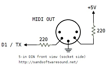
All the sender needs to do is to drive or remove an electrical current through the loop. When the loop is driven, the LED at the other end of the loop shines. When the current is removed, the LED turns off. The current loop is controlled by the Arduino send port (pin D1, also known as “TX”). The 220 ohm resistors are current limiting resistors that put a limit on the amount of current driven into the loop.

This MIDI OUT circuit gets the job, but is a little basic. Most practical commercial circuits use a driver (such as a CMOS 74HC125 buffer/driver IC) or a transistor switch. The driver provides a little more electrical assurance and protection on the sender’s side. Better to blow up an inexpensive driver IC than your Arduino!

I built both the MIDI IN and MIDI OUT circuits on an Adafruit Perma-Proto quarter-sized breadboard PCB. I like the layout of these boards and they have nice through-holes for soldering. They have the same layout as a quarter-sized solderless breadboard. In this case, you solder connections instead of inserting jumper wires and component leads into solderless breadboard holes. Please, note. If you want to use the circuits above, but are reluctant to solder, then by all means, use a solderless breadboard!

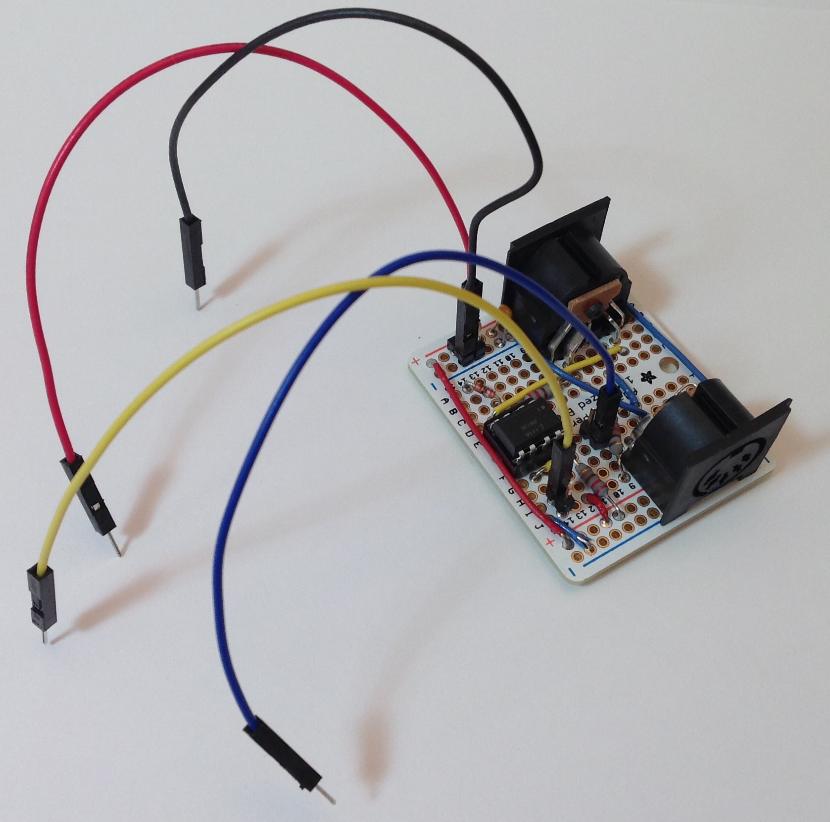
The following image shows the final result looking at the MIDI IN connector. Click the image for full resolution.

board_midi_in

The jumper wires sprouting from the board are not intended to make the board look like a court-jester. They are the connections to be made to the Arduino:

  • Red: +5 Volts
  • Black: Ground
  • Yellow: Connect to D0 / RX
  • Blue: Connect to D1 / TX

My construction style uses 2×1 and 2×2 headers to make external connections. The header pins mate up neatly with either Female/Female or Female/Male jumper wires. I used F/M jumpers in order to plug into the signal headers on a standard Arduino UNO for testing.

The next image shows the final resulting looking at the MIDI OUT connector.

board_midi_out

If you don’t mind soldering, but don’t want to go free-style on a prototyping board, then I recommend the Sparkfun MIDI Shield (DEV-12898). The latest revision of the MIDI Shield has good input protection and output drivers. It also has a RUN/PROG switch that is handy when uploading a sketch to the Arduino. MIDI and PC communications share the same serial port and conflicts must be avoided. (More about this issue in another post.) With the prototyping board, I just pull the yellow jumper wire when I upload a sketch.

The Sparkfun MIDI Shield has two knobs and three switches. This is a bonus if you are working with a standard Arduino. The knobs and switches go unused if you are working with a littleBits Arduino. In either case, the Sparkfun MIDI Shield is a viable alternative to “roll you own.”

Next time, I’ll describe the sketches that I wrote in order to test the MIDI IN and MIDI OUT.

Update: Use this simple MIDI sequencer sketch to test the MIDI OUT portion of the 5-pin interface.

littleBits Arduino tone sequencer

The littleBits Arduino module has the potential to be a MIDI-driven tone generator for a mono or paraphonic synthesizer. After getting the module, I was anxious to try it out even though I haven’t built a MIDI interface for it (yet).

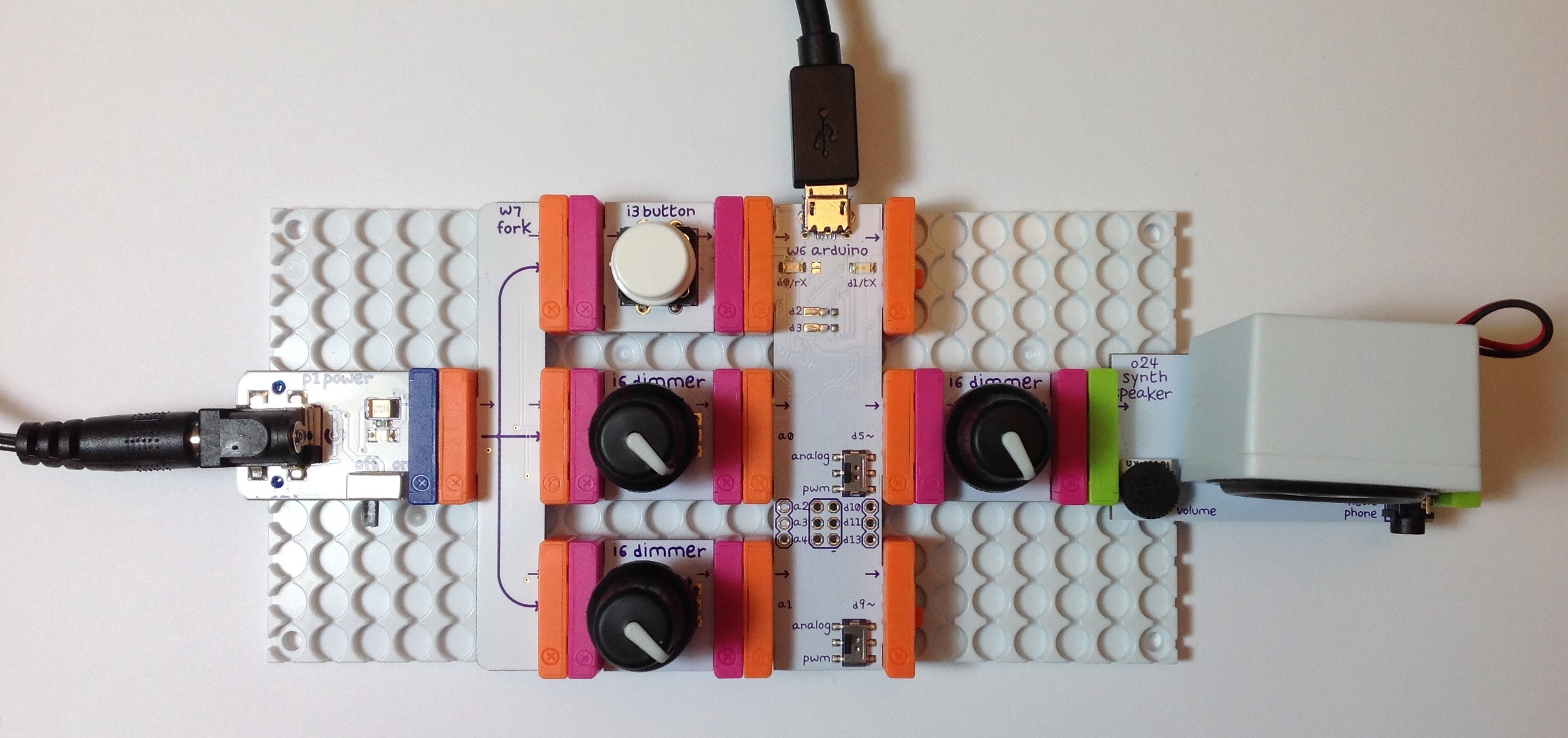
Here is a picture of the littleBits hardware. (Click the image to get full resolution.) The Arduino module is in the middle between the controls at the left (button and dimmers) and the synth speaker at the right. The controls on the left hand side don’t do anything at the moment. I put a dimmer between the output pin (D5) and the synth speaker in order to control audio volume. It’s just more convenient to control the volume with a dimmer than the tiny trim pot on the synth speaker module. The knobs on the dimmers are my own touch; they aren’t standard-issue with the littleBits dimmers.

arduino_dimmer_speaker

To keep things simple, I wrote a sketch that implements a basic note sequencer. Each note has a pitch (frequency) and a duration (milliseconds). The notes are stored in an array. The Arduino loop() function steps through the array of notes and plays one note at a time. After the loop plays the last note in the array, it goes back to the beginning of the array. The loop has a delay() in it and the loop keeps track of the remaining duration of the currently playing note. The sketch calls the Arduino tone() function to play notes by sending a square wave at the desired frequency to output pin D5.

If you would like to learn more about this project, then read about the design of this simple Arduino-based sequencer and tone generator. Here are links to the source code:

ToneTest.ino: Main sketch
ToneFreq.h: Note frequencies
ToneNote.h: Note durations

The D5 and D9 output pins on the littleBits Arduino module have a switch that enables or disables low pass filtering. The “analog” switch position turns on the filtering. The “pwm” position turns filtering off. Should you build this project yourself, try both switch positions. The “pwm” position doesn’t filter the square wave and you will hear it loud and nasty. The “analog” position produces a quieter, mellower timbre thanks to the low pass filter. Be sure to try the littleBits synth filter, envelope and delay modules, too.

One more tidbit. Pictures of the littleBits envelope, filter and delay modules usually show the top-view. The picture below flips the modules over and shows the bottom-view.

envelope_filter_delay

From left to right, the modules are the envelope, filter and delay, respectively. There is some serious electronics on these boards! (Click the image for full resolution.) I hope to use these modules to mangle audio, not just synthesis.

All the best.

Update: 28 June 2016. If you enjoyed this project and have the littleBits Synth Kit, then check out an expanded version of the tone sequencer which drives the filter and envelope modules.

Tenor to the max!

A few posts ago, I deconstructed the Yamaha MOX (Motif XS) tenor saxophone patches. The article summarizes the waveform assignment and Expanded Articulation (XA) control for each element within a preset voice. I’m not going to dive into the basics here, so I recommend reviewing the article for background information on XA and its behavior.

The blog entry covered the MOX (Motif XS) tenor sax presets, but not the newer Motif XF (MOXF) presets. The XF series workstations have two additional waveforms:

  1. Tenor Sax2 Growl
  2. Tenor Sax2 Falls

bringing the XF up to the level of Tyros/PSR Super Articulation tenor sax voices. This article deconstructs the “Tenor MAX” preset which makes use of these additional waveforms. The analysis is relevant even in the Montage era because the Montage tenor sax is based upon the XF waveforms (no update in the new model).

Pushing the main topic aside for a moment, Super Articulation 2 (SArt2) voices are a whole different technology and even to this day, the Motif and Montage do not implement SArt2 voices. SArt2 seems to be a premium feature that is reserved for Tyros. SArt2 requires realtime analysis of playing gestures and computation which is beyond basic AWM2 synthesis.

The table below gives the waveform, key range, and velocity range for each element in the “Tenor MAX” patch.

    Elem#  Waveform            XA        Notes   Velocity
    -----  ------------------  --------  ------  --------
      1    Tenor Sax2 Soft     AllAFOff  C-2 G8    1   79
      2    Tenor Sax2 Med      AllAFOff  C-2 G8   80  110
      3    Tenor Sax2 Growl    AllAFOff  C-2 G8  126  127
      4    Tenor Sax2 Hard     AllAFOff  C-2 G8  111  125
      5    Tenor Sax2 Hard     AF2 On    C-2 G8    1  127
      6    Tenor Sax2 Falls    AF1 On    C-2 G8    1  127

When the AF1 and AF2 buttons are OFF, one of the first four waveforms are triggered based upon the key velocity. The four elements cover the dynamic range from soft, through medium, through hard, all the way up to growl. The AF1 and AF2 buttons select particular waveforms depending upon the player’s intention. When AF2 is ON, all key velocities trigger the hard waveform. When AF1 is ON, all key velocities trigger sax falls.

So, bottom line, the “Tenor MAX” programming is just about what I expected.

I hope the analysis of tenor sax programming has helped you to understand XA and Motif/MOX voice programming. If you’re a Tyros/PSR player, then I hope that this analysis has helped you to understand a little bit of the technology beneath the Super Articulation voices.