The Yamaha Montage is one heck of a fine keyboard! Let’s take a quick look inside.
The Montage hardware is a new platform. Sure, there are a few things borrowed from older products, but that’s like blaming Apple for reusing a USB controller. The digital and analog electronics are all new.
There are several printed circuit boards and I will only cover the main PCBs.
- PNL/PNR: Handles the front panel buttons, knobs, sliders, master volume and gain.
- LCD: Bridge between the LCD controller in the main CPU and the 7inch TFT WVGA LCD touch panel.
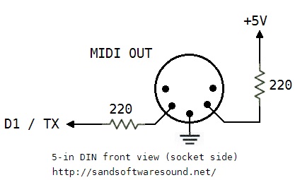
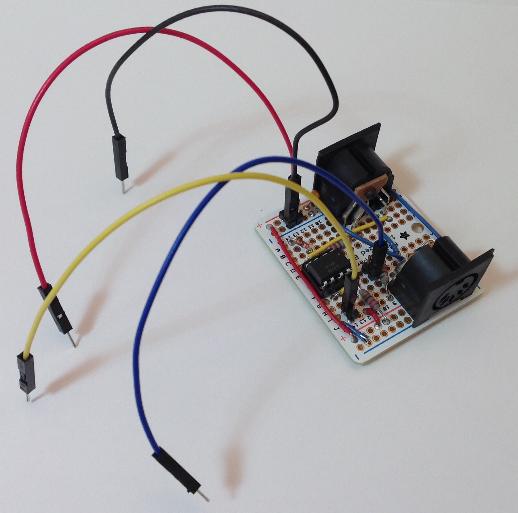
- DJK: Digital jacks (foot controllers, foot switch, sustain, MIDI)
- AJK: Analog electronics and jacks (DACs, ADC, balanced/unbalanced outputs, analog input, phones).
- DM: Digital electronics (main CPU, tone generators, external USB and Ethernet interfaces).
A few ports and connections are “Debug only” and are not populated or used in normal operation. The Ethernet port to the main CPU is debug only, for example.
The separation of the digital and analog electronics and jacks is significant. When the Montage was first introduced, I mentioned that “Pure Analog Circuit (PAC)” appeared to be an exercise in old school engineering that pays careful attention to board layout, component selection and clean power. The AJK board bears this out. The AJK board contains the stereo DAC and ADC components:
- Audio ADC: Asahi Kasei AK5381VT-E2 24-bit ADC (96KHz max)
- Audio DAC assignable output: Asahi Kasei AK4393VM-E2 24-bit DAC (96KHz max)
- Audio DAC main output and phones: Asahi Kasei AK4393VM-E2 24-bit DAC
The ADC and DACs communicate with the DM board over an audio backbone. Physical separation keeps digital circuits (with fast rise/fall times) away from analog signal paths. The AJK board also has its own voltage regulators. They ain’t kiddin’ about PAC!
Yamaha adopted ARM architecture processors for the first time in the Reface series. (See my article about the Reface CS and Reface DX internals). Montage continues this trend.
- The PNL board contains an MB9AF141NA ARM microcontroller with a 40MHz internal clock. The ARM microcontroller is assisted by a Toshiba TMP89FW24AFG microcontroller (SOC) operating at 10MHz. In Yamaha’s terminology, this ARM is a “sub CPU.”
- The main CPU is an AM3352BZCZ80 ARM microprocessor with an 800MHz CPU clock. It is a Texas Instruments Sitara ARM Cortex-A8 single core MPU.
The ARM Cortex-A8 is a major departure from the Motif line which employed MIPS architecture microprocessors (such as the Toshiba TX4939C) as the main CPU.
We first saw the new SWP70 tone generator in the Yamaha PSR-S970 arranger workstation. The SWP70 replaces the SWP51L which has been the mainstay in mid- to upper-tier Yamaha products for several years. Top-tier products (e.g., Motif XF and Tyros 5) have two SWP51L tone generator chips which together share a common wave memory. The two SWP51Ls split AWM2 voice and DSP duties.
So, it isn’t any surprise to see two SWP70s in the Montage. What is suprising, however, is how the Montage’s two SWP70s are deployed. The two SWP70s are not connected in the “classic” structure. Instead, the microarchitecture is assymetric.
- TG Master: The TG Master is connected to wave ROM (flash), wave RAM (SDRAM), and DSP RAM (SDRAM).
- TG Slave: The TG Slave is connected to DSP RAM (SDRAM) and an SSP2 processor (through an ASIC gate array bridge).
I’ll have more to say about the SSP2 in a moment. The bridge connects the TG Slave’s serial audio interface to the SSP2 and the bridge carries several channels of digital audio (I2S format) to/from the TG Slave and the SSP2.
Of course, one’s first thought is to presume that the TG Master handles AWM2 voices and the TG Slave handles FM-X voices. There’s a lot of generation and DSP resources within an SWP70, so I doubt if they are left idle in the TG Slave even though the TG Slave does not have memory memory! There is a sixteen bit wide bus between the TG Master and Slave — not really sufficient to carry the sample bandwidth needed for AWM2 tone generation, however.
Each SWP70 has 16MBytes of SDRAM for DSP working memory. The TG Master has 32MB of Wave RAM. The Wave RAM is a cache for samples that are read from wave flash. (See my earlier article about the SWP70 and U.S. Patent 9,040,800.) Commodity NAND flash (as one would find in an SSD) favors sequential access; random access is horribly slow. The Wave RAM caches samples that are read from NAND flash.
Now, the big question: How much wave memory? The Montage wave memory consists of four Spansion (Cypress) S34ML08G101TFI000 8Gbit, ONFI-compliant devices with a total physical capacity of 4GBytes. In classic fashion, the memory is separated into upper and lower bytes. The Yamaha specifications state wave size as, “Preset: 5.67 GB (when converted to 16 bit linear format), User: 1.75 GB.” Assuming a 2.52 aggregate compression factor, the arithmetic works out in the following way:
4GB physical = (5.67GB / 2.52) preset + 1.75GB user
The Motif series has an aggregate compression factor in this ballpark.
The Montage has a common multi-channel serial audio bus (I2S format) that interconnects the main CPU, TG Master, TG Slave, SSP2, ADC and audio DACs. This is the digital audio backbone. The bus conveys digital audio from the generators and effects on the DM board to (from) the converters on the AJK board.
The SSP2 is a Yamaha proprietary processor which is used in many products: Reface CS, Reface DX, PSR-S950 workstation, etc. The SSP2 integrates signal processing, USB, serial audio, and more. It is the “designated hitter” for Yamaha designs. When Yamaha needs a flexible chip with DSP and interfacing skills, it calls on the SSP2. (Roland have a similar jack of all trades called the “ESC2.”)
The Montage’s SSP2 has only 2MBytes of NOR flash memory on its CPU bus. That’s not a lot of program space! The SSP2’s USB port is connected to the external “USB TO HOST” interface. The SSP’s other interfaces convey digital audio to/from the digital audio backbone and the TG Slave. Thus, the SSP2’s main role is to route digital audio. The Montage can send 16 channels and receive 3 channels of stereo 24 bit/44.1 kHz digital audio to/from an external computer or iOS device
Commentary and opinion
I hope you find this quick overview to be informative and helpful. I try to present the system structure objectively without too much speculation.
Please discuss the Montage responsibly! Yamaha have a definite design style which exploits their expertise in very large scale integration (VLSI) as a strategic advantage. When Yamaha specify maximum polyphony as “128 AWM2 and 128 FM-X”, that’s 128 each all day long without any dependencies on the number of effects in use, etc. Some people lament this approach and wish that Yamaha would base their systems on x86 even though x86 is not always the best choice for embedded systems. Yamaha are no strangers to x86 having obtained many patents covering x86-based tone generation back in the 1990s and early 2000s.
Before anyone carries on about SSDs and SATA, please study the design of the SWP70. The SWP70 memory interface has all of the power, flexibility and Open NAND Flash Interface (ONFI) compatibility as an SSD without the need for SATA bus protocol.
Users may rightfully be disappointed at the lack of user-installable expansion memory. Yamaha are not evil; they simply do not have a convenient way to provide user-installable memory at the chip level. I think users should lobby for more built-in expansion memory, but they shouldn’t delve into conspiracy theories about Yamaha’s engineering or managerial practice.
Some wag will undoubtably complain about “memory parts cost only $10,” “my jump drive is 32GBytes,” “the need to stream 100s of gigabytes,” etc. Fine. But, an instrument design is a just one design. It is what it is is. One should listen to the Montage with their ears, then question whether gobs of samples would improve the playability, sound or expression of the Montage. Also, if you really believe that you can build a better instrument at the same price point, by all means, line up the VCs and engineers, go to work, and compete.
The final result is what we hear with our ears. The hardware is important, but it is simply a platform for the “soft content” — the algorithms, code, waveforms and sound design. In the long run, the soft content is the biggest development expense and is the most important element in a successful digital musical instrument product.
Perspective. Chill. Peace.
Here are links to related articles on this site:
All site content is Copyright © Paul J. Drongowski