A recent thread on the Keyboard Forum (“What was the first song you figured out by ear?”) brought up memories of high school and combo organs. One of the most popular tunes of the time was “Space Rock Part 2” by The Baskerville Hounds. Air play on Ghoulardi was a big boost to its popularity and it really brought people onto the dancefloor. “Space Rock” is pretty much a rip of The Stones’ “2120 South Michigan Avenue,” albeit way up-tempo than the Stones’ version. Sly Stone knocked out his own titled “Buttermilk.” If you’re wanting a modern update, listen to the 2015 Jerry Cortez cover.
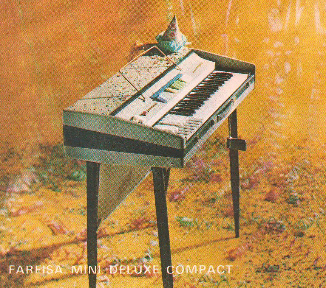
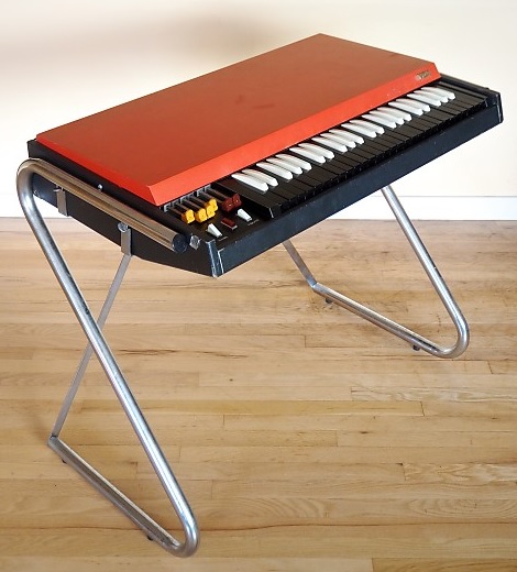
The “Space Rock” organ solo was the solo to know as a teen. At the time, I was paying off my Farfisa and didn’t have any money for records, so the old “drop the needle until you got it” method wasn’t for me. My bandmates were always on my back about it and they didn’t accept my “Guys, they’re just jammin'” excuse. I tried to cover the head and then improvise. Oh, well.
I’m pulling together a backing track for “Space Rock/2120” and it seemed like the time to transcribe the solo. Enter zPlane deCoda. In a nutshell, zplace have deployed their time/pitch stretching and DSP expertise to the problem of picking out tunes from audio. (See the Sound On Sound review for more information.) It’s not an audio-to-MIDI converter, so you still need to use your ears and eyes.
First, ya drag (or open) an audio file in deCoda. deCoda gives you two views: a standard (amplitude) waveform view of the audio and a spectrographic plot. The spectrographic plot is like a DAW piano roll. Instead of notes, however, it displays the sonic energy present at each pitch. You can (kind of) see the notes in the song — pitch and duration. I spent most of my time in the spectrographic display.
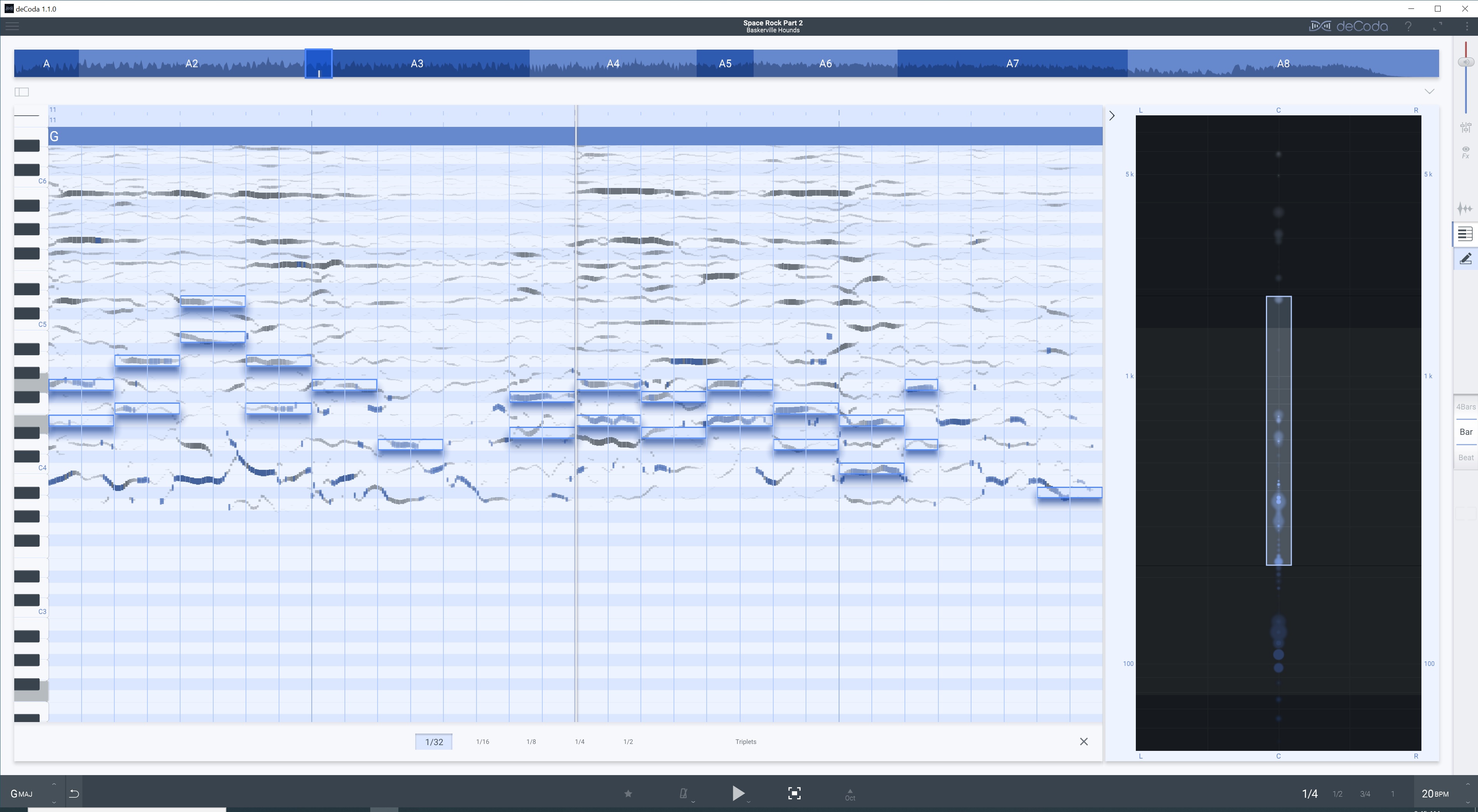
Optionally, you can turn on an XY panel (at right in the image above) that lets you focus playback and analysis on a particular “region” of the stereo field and audio frequency spectrum. Thanks to the XY panel, you can eliminate the bass and high-end sibilance. Blobs light up in the XY panel during playback as notes come and go.
deCoda offers a number of playback controls. You can playback at 1/4, 1/2, 3/4 and full speed. You can transpose up and down. You can change the tempo. My recommendation is to get the best mix of key, tempo and XY region before deep diving transcription.
Like Yamaha’s Chord Tracker, deCoda discovers key, tempo, chords and song sections. As mentioned, you can modify deCoda’s decisions. Compared against Chord Tracker, I would give Chord Tracker the edge. (Yamaha have invested a pile ‘o’ cash into music analysis.) Both tools handle simple chords OK, but forget jazz chords (no 11th and 13th chords) or gospel voicings.
After quickly munching “Space Rock”, deCoda had the key right, but half the actual tempo. The Hounds played “Space Rock” at a blistering 156 BPM. deCoda says 78 BPM. That’s OK, but…
One of the coolest deCoda features is the ability to draw notes on top of the spectrographic display. The notes play back through a simple synthesizer (think Casiotone). A mixer controls the relative level of song audio and synthesized tones. Once I got a little more skilled with deCoda, I found myself changing the relative levels quite often in order to A/B the original audio and the drawn notes. I wish deCoda offered a few different synth voices as the simple tones blended with the organ notes making it difficult to sort out the sounds by ear.
With a little practice, you can begin to pick out the notes by sight as well as ear. 1/4 playback is good for checking note start and duration. “Space Rock” is a mono mix and a mess of frequencies with that danged 60’s ring-y reverb. Thus, there are many false positives — places where you think there is an organ note, but it’s actually the frapping guitar. I wish deCoda could color notes according to timbre. Man, that would be quite the time-saver.
To compensate, I found myself playing the notes on keyboard, mainly to check fingering. “Space Rock” is one of those lazy blues tunes where the keyboardist just rocks his or her fingers around in one basic hand position. It’s difficult to read piano roll notes in real-time; I’d love to have even a simple staff viewer.
Now for the “but…”. deCoda can export the notes as a Standard MIDI File (SMF). Very good. deCoda produces MIDI notes that follow the identified tempo. When the SMF is imported into a DAW or notation tool, it arrives with the identified (or tweaked) tempo. Note play back sounds right, but if you change to the correct tempo in the tool, note starts and note durations are off (i.e., half of what they should be). I had to fix the note starts and durations in Sonar, save another SMF and import the modified SMF into Sibelius. Bummer.
I discovered the tempo and note export gotcha downstream. I also found that I wanted to work and play in G Major, not F# Major, AKA “that frapping guitar key.” I had already started a draft in Sibelius and it became a question of how much work I wanted to throw away. It’s better to get these considerations right from the start before export and downstream work.
Speaking of Sibelius, I really longed to have the identified notes in notation form, not piano roll. Under Windows 10, I couldn’t work in Sibelius and deCoda simultaneously. They did not work together — some kind of MIDI or audio system conflict. One or the other tool wouldn’t play when they were both open at the same time. In a few cases, I had to resort to notation paper and pencil to transfer identified notes into Sibelius, exit Sibelius, then re-start deCoda. Painful.
After all is done, I arrived at a decent transcription in Sibelius. (See image below; click to enlarge.) After seeing and playing the solo against a rough backing track, I think deCoda is about an eighth to a quarter note ahead of the beat. I’m not sweating it too much as playing “Space Rock” comes down to feel. However, it might be a factor when an accurate score is needed for chart-driven players.
zplane deCoda is a worthwhile tool. It won’t automatically transcribe, but it is a decent assistant. The note editor and MIDI export are a real boon as I a keep a book of charts for reference. The XY plot is also a worthy mix visualization tool and has been repurposed in zplane peel. I hope that deCoda continues to invest in deCoda as I would love to have timbre coloring. That’s a tough technical problem, but cracking that nut would put zplane way out in front competetively.
Copyright © 2021 Paul J. Drongowski