
The last time that I took a look at Yamaha XG effects, I discussed using the VARIATION effect as a channel insertion effect. I’m now working on a PSR/Tyros style where I would like to apply an amp simulation effect to two channels. So, it’s time to learn about the configuration of VARIATION effects in SYSTEM mode. Even though I’m working on a style, you can apply these techniques to any Standard MIDI File (SMF) for play-back on an XG sound engine.
XG insertion effects are relatively easy to configure as the VARIATION effect is added to the signal chain of a single MIDI channel (XG part). Configuration of the VARIATION block as a SYSTEM effect takes more effort (i.e., more System Exclusive messages), but is well worth it. Now that I understand SYSTEM mode better, I may set up a DAW template for SYSTEM mode and use that template as my default effect configuration.
The diagram below shows the signal flow for the VARIATION, CHORUS and REVERB effect blocks when VARIATION is configured for SYSTEM mode. I show only one channel (Part NN) entering from the left in order to keep the diagram simple. Control “knobs” are drawn as ovals; these are XG/MIDI parameters under your control. The first four knobs — CC91, CC93, CC94 and DRY — are per-part parameters and need to be set for each of the sixteen channels (parts). The MIDI Continuous Controller (CC) knobs set the reverb, chorus and variation send levels for the part, respectively. In my project, I set the variation send (CC94) for two parts to non-zero levels and set CC94 for the remaining parts to zero. The non-zero levels pass the signal to the VARIATION block.
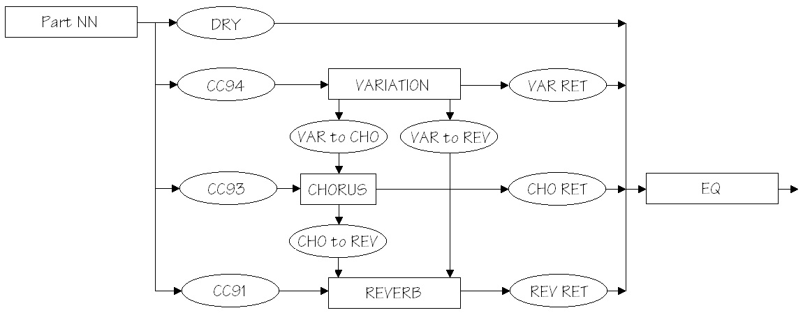
The reverb, chorus and variation send levels are configured using MIDI Continuous Controller messages, but the DRY level is set using an XG System Exclusive (SysEx) message. Although this looks inconsistent, it follows Yamaha’s XG recommendations, i.e., use CC messages in preference to SysEx where possible. DRY level must be controlled using SysEx as no corresponding MIDI CC message is defined.
Please see the table at the end of this post for further message programming details.
The rest of the effect blocks and knobs are global (system-wide). The REVERB, CHORUS and VARIATION return levels (REV RET, CHO RET, and VAR RET) along with the DRY levels determine the amount and balance of effected and un-effected (dry) sound. All of the return levels default to 0dB (decimal 64 or 0x40 in hexadecimal notation). The default for each per-part DRY level is the maximum (decimal 127 or 0x7F). These default values enable signal flow right from the beginning and are a good starting point for experimentation and tuning. At least you are guaranteed to get some sound out of the effect section!
The VARIATION, CHORUS and REVERB blocks need to be configured through the usual XG SysEx voodoo. You need to select at least the effect type and be sure to configure the VARIATION effect for SYSTEM mode. In actual practice, you should do this before setting any send levels as the change to SYSTEM mode changes the level parameters to new default values.
Now the fun begins! The default configuration puts the three effect blocks in parallel. The inter-block send levels:
- Send VARIATION to CHORUS (VAR to CHO)
- Send VARIATION to REVERB (VAR to REV)
- Send CHORUS to REVERB (CHO to REV)
establish serial effect routings between blocks. The level values determine the degree to which a series connection is made (i.e., how much signal is passed). Initially, all of these knobs are set to zero and the effects are full parallel. You can change these values to add reverb and/or chorus to the effected variation signal, for example, in the same way that you add reverb and/or chorus to a part.
The higher end arranger workstations offer a rich choice of CHORUS block effects — everything from chorus, phaser and flange to rotary speaker. Thus, you can create a long effect chain from VARIATION to CHORUS to REVERB, if you so desire. Want to phase a distorted guitar sound? You can!
The following tables summarize the low level details of effect programming. The addressable XG parameters must be set with the usual SysEx magic, e.g., F0 43 10 4C 02 01 40 4B 01 F7 to set the effect type.
Continuous Controller (Per part/channel)                    "Knob"

  CC91  Part/Channel REVERB SEND                            (CC91)
  CC92
  CC93  Part/Channel CHORUS SEND                            (CC93)
  CC94  Part/Channel VARIATION SEND                         (CC94)

MULTI PART (per part/channel NN)

  Address   Parameter             Default
  --------  --------------------- -------
  08 NN 11  DRY LEVEL             0x7F                      (DRY)
  08 NN 12  CHORUS SEND           0x00
  08 NN 13  REVERB SEND           0x28 (decimal 40)
  08 NN 14  VARIATION SEND        0x00

REVERB effect block (global)

  Address   Parameter             Default
  --------  --------------------- -------
  02 01 00  REVERB TYPE           0x01, 0x00 (HALL1)
  02 01 0C  REVERB RETURN         0x40 (off:0x00, 0dB:0x40) (REV RET)
  02 01 0D  REVERB PAN            0x40 (center)

CHORUS effect block (global)

  Address   Parameter             Default
  --------  --------------------- -------
  02 01 20  CHORUS TYPE           0x41, 0x00 (CHORUS6)
  02 01 2C  CHORUS RETURN         0x40 (off:0x00, 0dB:0x40) (CHO RET)
  02 01 2D  CHORUS PAN            0x40 (center)
  02 01 2E  Send CHORUS to REVERB 0x00 (off, 0dB:0x40)      (CHO to REV)

VARIATION effect block (global)

  Address   Parameter             Default
  --------  --------------------- -------
  02 01 40  VARIATION TYPE        0x05, 0x00 (DELAY LCR2)
  02 01 56  VARIATION RETURN      0x40 (off:0x00, 0dB:0x40) (VAR RET)
  02 01 57  VARIATION PAN         0x40 (center)
  02 01 58  Send VAR to REVERB    0x00 (off, 0dB:0x40)      (VAR to REV)
  02 01 59  Send VAR to CHORUS    0x00 (off, 0dB:0x40)      (VAR to CHO)
  02 01 5A  VARIATION CONNECTION  0x00 (insert:0, system: 1)
  02 01 5B  VARIATION PART #      0x7F (off: 0x7F)