Where to put AN-X™?

Let’s not miss the forest for the trees…

Wishful thinking abounds — Let’s add an AN-X™ engine to the Yamaha Montage and/or MODX+. From the comments, you would think this is a done deal.

Well, the frenzied demand is certainly there. 🙂 With demand wafts the smell of money. How will Yamaha make money with AN-X?

Occasionally I see a forum comment that is so spot-on, it bears repeating. This comment comes from CyberGene on the Musicplayer Keyboard Corner:

The more I think about it (and knowing Yamaha of course, as well as owning and selling a MODX for being too awkward to work with) I have no high hopes for this hypothetical AN-X being integrated into anything intuitive and easy to use. 🙂 Most certainly it would need to be preprogrammed in advance rather then having a good hands on interface for real time manipulation. Yeah, you can route the knobs and faders to it as usual but still — I just think they should make a YC/CP type of instrument where they add the entire reface CS panel and engine. 😉 Why not add it to the YC73/88, so that it becomes a Nord Stage competitor. Call it a YCS73/88, bingo!

Amen. Could you imagine programming or controlling an AN-X engine within the context of the current Montage (MODX) user interface (UI)? Kill me now.

If Yamaha learned one thing from the YC and CP stage instruments, it’s “stage instruments with a focused user interface and engine (drawbar organ, piano, whatever) are desirable and sell.” [Ka-ching.]

Yamaha marketing folks are players as well as business people. The right way to do analog is to put the engine in a box that it is studded with knobs, buttons and analog controllers. Analog synthesis is meant to be interactive. Yamaha marketing surely knows this and the Reface CS — on a small scale –is proof.

So, AN-X on Montage and MODX+? How would that fit within a menu-based UI which many people find too complicated? In the case of MODX+, would you be happy with four sliders, four knobs and a Superknob for control? Would you enjoy menu-diving? [Sound of shrieking noises here.]

So, thanks, CyberGene for your insight. If Yamaha want to do AN-X right, they need to do it in a focused stage instrument. And make money.

Update: Yamaha have filed for a stylized (figurative) trademark in the European Union. See image below.

Yamaha trademark ANX (European Union, filing: 018741845)

Copyright © 2022 Paul J. Drongowski

Akai MPK Mini Play: GM/GS MIDI mod

In order to make your Aka MPK Mini Play (Mk1) into a GM/GS module, you must modify its hardware. As it is with all mods, modifications void the warranty, could damage the keyboard, and may affect resale value. The risk is yours alone.

That said, I’ve now thoroughly tested my Akai MPK Mini Play (Mk1) MIDI mod. Not only is a General MIDI module hiding inside, it does Roland GS, too!

Recapping, the MPK Mini Play main printed circuit board has a group of test pads for the internal synthesizer. The test pads are bigger than surface mount (SMT) traces, which makes soldering much easier. I tapped four signals and brought them out from the board on a ribbon cable:

  • SAM2635_RX: MIDI IN (white wire)
  • SAM2635_TX: MIDI OUT (black wire)
  • D Ground: Ground for external power (grey wire)
  • D +3.3V: +3.3V for external power (purple wire)

“SAM2635” refers to the Dream S.A.S. SAM2635 synthesizer chip — the MPK Mini Play’s tone generator.

Akai MPK Mini Play (Mk1) test pads (before and after)

I did a reasonably thorough analysis of the internal MIDI messages and the Mini Play’s MIDI over USB implementation. The Akai software is much too limiting and I became determined to unleash the Kraken within (the SAM2635).

Akai MPK Mini Play (Mk1) connected to UBLD.IT MIDI breakout board

I connected the other end of the ribbon cable to a UBLD.IT MIDI breakout board. The UBLD.IT board provides Akai MPK Mini Play 5-pin MIDI IN and MIDI OUT ports to the Dream SAM2635. I recommend turning INTERNAL SOUNDS off so controller messages do not interfere (collide) with incoming 5-pin MIDI messages. Don’t expect signals/messages to merge.

What else do you need to start using the SAM2635 as a MIDI module? Documentation! The Dream S.A.S. web site has:

You can skip the datasheet, but you will definitely need the firmware and sound bank guides.

The firmware guide describes the GM/GS implementation including, of course, the supported MIDI messages. You’ll find a few interesting and useful enhancements beyond General MIDI and Roland GS:

  • Several selectable reverb and chorus effect types.
  • 1-, 2- or 4-band equalization.
  • A spatial effect.

Near as I can tell, the microphone and CODEC are not connected in the MPK Mini Play electronics. Maybe you’ll discover a hack of your own…

The sound bank guide describes the available voices and drum kits:

  • 128 General MIDI instruments.
  • Nine drum sets and one sound effects (SFX) set.
  • 225 variation instruments.

The variation instruments are a true bonus. You get additional electric pianos, organs, guitars, synth basses and orchestral instruments. The variations are a little light on synth leads and pads, but I think you are expected to roll-your-own by programming amplitude and filter characteristics via MIDI CC messages. The GS implementation offers many options that way.

How does it sound? Here is an MP3 of my standard GM test: Traffic’s Feelin’ Alright. Compare with the Yamaha PSS-A50 rendition. There is a decent piano solo during the last 30 seconds or so, if you want to skip ahead.

I pulled together links to all of my previous articles about the Akai MPK Mini Play (Mk1):

All in all, this has been a successful hack!

Copyright © 2022 Paul J. Drongowski

Yamaha MODX+ madness

Thanks to a few pages posted from the Yamaha MODX+ user manual, the new MODX+ is a bit of a nothing-burger — a product spiff. The MODX+ got a few bumps over MODX (Mark 1): more expansion memory (1.75GB), FM-X polyphony on-par with Montage (128), and a way to add rhythm patterns:

Also, the MODX+ has a new feature for instantly adding rhythm patterns so that the players can take their music creation forward with dynamic rhythm parts. With this feature, creating rhythmic changes in the “Motion Controls” is easier than ever! [Yamaha]

Just enough to keep MODX+ competitive in its price bracket. The bump in FM-X polyphony indicates the likely addition of a second SWP70 tone generator IC.

I suspect Yamaha will use new downloadable libraries to drive a few pack-rat punters to upgrade to MODX+. Recently, IdeaScale participants had a chance to preview a new CP-80 voice (and waveforms). Yamaha were soliciting opinions as to which voices/waveforms had the most sonic appeal. A flood of must-have content might create demand among current MODX (Mark 1) players, making that 1.75GB a necessity.

The forums are filled with speculation about AN-X™. Again, a lot of wishful thinking about AN-X coming to Montage and/or MODX+. Only Yamaha know for sure.

As yet, however, no one has solved the mystery of the other registered trademarks: CK61™ and CK88™.

Yamaha have moved on from the SSP2 signal processing chip to the SSP3. The SSP3 first appeared in the Yamaha AXR4U and Steinberg UR44C audio interfaces. Yamaha move ahead like a shark and the SSP2 is deprecated for new designs. In fact, the MODX+ refresh likely includes the SSP3 as SSP2 production inventories must be low or exhausted.

That turns my attention to the Reface DX and Reface CS. The Reface DX and CS are sisters, sharing the same internal design modulo screen interface and front panel gizmos. Both are based on SSP2 and, thus, both may be in need of a refresh — or replacement. The SSP2 signal processor provides the FM and VA synthesis horsepower.

Simply put, will CK61 and CK88 replace the Reface DX and CS? Will the CK61 and CK88 be the AN-X machine? How will Yamaha monetize AN-X? When it comes to business, Yamaha are not fools. Never sell one model when two will do as well! Ka-ching. 🙂

On a personal note, I started this site to inform players about music technology and what’s inside the tin. It’s gratifying to read the forums and see how much this site has influenced discussion, especially discussion about Yamaha products. Thank you for reading and please keep coming back! — pj

A few handy links:

Copyright © 2022 Paul J. Drongowski

Is MODX+ on the way?

[Updated 18 August 2022.] Rumors are circulating about Yamaha MODX — either replacement or refresh.

Now pictures of a misdelivered “MODX8+” have appeared. Naturally, one asks “fake or real?” Cosmetically, the only external differences are:

  • A different product model legend on the right side of the top panel, e.g., “MODX8+ Music Synthesizer”.
  • Black plastic end-cheeks instead of grey.

The MODX8+ was shipped mistakenly to a customer. Support anticipates release in the Sepember or October timeframe.

MODX8+ real or fake?

The new livery reminds me of the Yamaha MX series V2 spiff. It was somewhat difficult for a customer to identify an MX V1 vs. an MX V2. The new MODX+ legend makes the mark 2 clearly distinguishable. No word about enhanced features or sound set. One must also ask if the Montage will get a spiff, too?

I’m going out on a limb — real.

Update: MODX+ discussion is rampant in the forums. Here are a few quick comments, corrections and a request.

SWP70 is an integrated circuit designed by Yamaha. It is manufactured by a partner fab. Yamaha is fab-less. Yamaha transferred its semiconductor manufacturing subsidiary to Phenitec Semiconductor in 2014. It takes a lot of money to build and maintain semiconductor fabrication factories — a money losing proposition for Yamaha (or my old employer, AMD, for that matter). Yamaha remains a manufacturing powerhouse at the board level and sells its own line of PCB assembly equipment.

SWP70 processors are manufactured in batches based on Yamaha’s estimated need. Depending upon the portability of the SWP70 design, Yamaha may turn to multiple alternative partners for fab. “Portability”, in this sense, means how easily the design can be re-targeted for a specific fabrication process.

Generally, Yamaha has done a good job exploiting commodity components. The SWP70 uses ONFI-compatible NAND flash and RAM. The MODX and Montage host processors are high-volume, embedded ARM microcomputers. Although Yamaha has preferred suppliers for NAND flash and RAM (e.g., Cypress/Spansion, Winbond), these are commodity parts and are available from many suppliers. Commodity components are probably not a pressure point.

As I’ve said before, Yamaha have just a few critical external supply vulnerabilities. Aside from fab capacity, SWP70s or other Yamaha proprietary processors are likely not the issue here. When it comes to DACs and ADCs, however, Yamaha is very reliant on Asahi Kasei Microdevices (AKM). AKM is still trying to recover from its factory fire. The AKM supply shortage has put Yamaha and many other vendors on the back foot.

Yamaha have the right to substitute components. Every manual has the following disclaimer:

Specifications and descriptions in this owner’s manual are for information purposes only. Yamaha Corp. reserves the right to change or modify products or specifications at any time without prior notice. Since specifications, equipment or options may not be the same in every locale, please check with your Yamaha dealer. Visit the web page for information on the latest Owner’s manual.

Of course, this could mean substituting for AKM devices. DACs and ADCs communicate via the I2S digital audio interface format. If Yamaha did substitute — speculation — would we hear an audible change?

Much speculation surrounds the second, unpopulated SWP70 position (TG slave) on the original MODX printed circuit board. The TG slave has an associated open position for DSP RAM only. Thus, if Yamaha choose to use the same board and to populate the open positions, these changes would bring MODX+ up to the same polyphony spec and tone generation horsepower as the current Montage. Montage would still have the advantage in digital audio routing and processing (including audio channels over USB). The original MODX board does not have provisions for upgraded audio channels.

A product spin is needed when a Yamaha proprietary component is obsoleted and out of inventory. Such may be the case with the venerable SSP2 — a workhorse in many Yamaha products including mixers, Reface CS and Reface DX. Yamaha and Steinberg have moved on to the SSP3.

Finally, a request. Please do not publicly reveal your source of leaks. Yamaha are incredibly paranoid, exceeded only by Apple and Sony in this regard. First, leaks get real people in trouble. Second, Yamaha learn from their mistakes. Protect your sources and methods!

Copyright © 2022 Paul J. Drongowski

Akai MPK Mini Play mod: MIDI IN success

I performed a few more quick experiments over the weekend and I’m happy to report further success!

Although the Akai MPK Mini Play has an internal Dream S.A.S. SAM2635 synthezier chip, the Akai microcontroller software blocks full access — a true shame because the SAM2635 firmware is a complete General MIDI/GS implementation.

I modified an Akai MPK Mini Play bringing out four signals from the main printed circuit board (PCB):

  • MIDI IN white wire: SAM2635_RX MIDI input
  • MIDI OUT black wire: SAM2635_TX MIDI output
  • Ground grey wire: Ground for external power
  • +3.3V purple wire: +3.3V for external power

My goal is to override the Arm microcontroller and drive the SAM2635 over 5-pin MIDI, completely bypassing the Akai software. If successful, we should be able to use the fully functionality afforded by the SAM2635.

Test 1: UBLD.IT MIDI breakout board

A full test of the UBLD.IT MIDI breakout board is in order before testing the MPK Mini Play. If the UBLD.IT isn’t working, any test with the Mini Play will fail, too.

UBLD.IT MIDI breakout board schematic (CC)

The UBLD.IT board is a really nice, small MIDI IN and MIDI OUT breakout board. The MIDI OUT side is dirt simple and sends the transmit signal (pin 1 of J2) to the 5-pin DIN connector through a current limiting resistor (R4). Please recall that MIDI is an active LOW current loop. The return pin — the other side of the current loop — is connected to VCC (the positive voltage rail) through a current limiting resistor (R1).

The MIDI IN side provides the opto-isolated MIDI logic signal to the receiving electronics. DIN pins 4 and 5 send the incoming current through the LED in the opto-isolator (U1). The opto-isolator is a 6N138. The LED shines on a photo-transistor. The photo-transistor is essentially a light-controlled pull-down path from the positive voltage rail to ground. Thus, the MIDI logic signal is HIGH when idling and is active LOW. The incoming logic signal is sent off the board through the receive pin (pin 2 of J2).

The test set-up is simple. Jumper the transmit and receive pins (J2). Connect +3.3V and Ground using the Mini Play as a power source. Connect UBLD.IT MIDI IN to the MIDI OUT of any handy keyboard like a Yamaha MODX. Connect UBLD.IT MIDI OUT to the MIDI IN of a second keyboard like a Yamaha Genos. Turn on the Mini Play to apply power to the interface. Play the sending keyboard (MODX) and listen for sounds produced by the receiving keyboard (Genos).

It was gratifying to hear the Genos while playing MODX, i.e., the UBLD.IT is working correctly.

Test 2: Play using an external keyboard

The next test is to drive the Akai MPK Mini Play itself.

Here’s the test set-up. Leave the MODX connected to UBLD.IT MIDI IN. Disconnect UBLD.IT MIDI OUT since we don’t need it. Connect the UBLD.IT pins (J2) to the corresponding Mini Play signals. Receive is SAM2695_RX (white wire) and transmit is SAM2695_TX (black wire). Leave ground and +3.3V connected (grey and purple wires, respectively).

UBLD.IT MIDI board connected to Akai MPK Mini Play

Turn on the Akai MPK Mini Play. Play the MODX. You should hear sounds produced by the SAM2635. Yay! 🙂 Try the MODX MOD and pitch bend wheels.

I believe this design works electronically because MIDI is active LOW and idles in the HIGH state. The pull-down transistor in the opto-isolator pulls the SAM2635_RX node LOW. Normally, you cannot tie two logic outputs together, but the pull-down works in this situation. (Think “wire OR”.) By the way, you shouldn’t play the Mini Play keys or turn its knobs as MIDI signals from the Arm microcontroller will interfere with the MIDI IN logic signal! I recommend turning INTERNAL SOUNDS off when using the 5-pin MIDI IN.

The next step is to try the Dream SAM2635 as a GM/GS synthesizer. Stay tuned.

Copyright © 2022 Paul J. Drongowski

Akai MPK Mini Play: MIDI over USB implementation

I performed experiments to discover how the Akai MPK Mini Play behaves when controlled through its USB port. I wanted to build on what I had already learned about the MPK Mini Play’s MIDI implementation.

As mentioned in earlier posts, the Mini Play’s host Arm microcontroller communicates with a Dream S.A.S. SAM2635 synthesizer chip:

            Arm       TX  ----> MIDI IN (RX)     Dream 
Microcontroller SAM2635
USART RX <---- MIDI OUT (TX) Synthesizer

The Arm sends MIDI messages to the SAM2635 when INTERNAL SOUNDS are turned on, i.e., when the INTERNAL SOUNDS button is lit. When INTERNAL SOUNDS are turned off, the Arm software sends MIDI messages over USB exclusively. Oddly, the Arm sends some MIDI messages over USB when INTERNAL SOUNDS are on — and not always on the expected MIDI channel! Very quirky or buggy, depending upon your point of view.

People who want a 16-channel multi-timbral MIDI module are going to be disappointed. When driving the MPK Mini Play through USB, you really have only two channels: MIDI channel 1 for regular, melody voices and MIDI channel 10 for drums. If you stick to these two channels, you’ll stay out of trouble.

If you venture off the path, however, you’ll be in the deep weeds. The Mini Play responds to NOTE ON and NOTE OFF messages on “keyboard” channels 2-9 and 11-16, playing the default Grand Piano sound. Such joy is misleading, however. Send a program change on channels 2-9 and 11-16, and the program change is redirected to channel 1! Do not send program change to any other channels than 1 and 10 if you value your sanity!

I think someone at Akai envisioned the MPK Mini Play as a two channel MIDI controller with optional synthesis on two channels. Unfortunately, the actual implementation is inconsistent with this model as far as synthesis is concerned. Worse, Akai doesn’t provide any documentation about the MIDI implementation letting punters poke around in the buggy weeds.

All of this is truly a shame knowing that the Dream SAM2635 is a full 16-channel GM/GS synthesizer. What a waste of silicon (AKA “sand”) by Akai!

Here are some additional details about the MIDI implementation such that it is.

The Arm software filters out all System Exclusive (SysEx) messages other than its own. Stated another way, if you send SAM2635 SysEx, it will never be delivered. So, you cannot send GM or GS reset, tweak reverb and chorus parameters, and so forth because these are all done via SAM2635 SysEx.

The Arm software does pass all MIDI Continuous Controller (CC) messages to the SAM2635. RPN and NRPN commands also get through because these kind of commands are formed using CC messages. Here are the MIDI CC messages which appear to work:

    CC#0    Bank Select (MSB) 
CC#1 Modulation wheel
CC#6 Data Entry
CC#7 Volume (channel volume)
CC#10 Pan
CC#11 Expression
CC#74 TVF cutoff frequency
CC#91 Reverb send level
CC#71 TVF resonance
CC#93 Chorus send level
CC#73 Envelope attack time
CC#72 Envelope release time
CC#80 Reverb program
CC#81 Chorus program
CC#91 Reverb send level
CC#93 Chorus send level
CC#98 NRPN LSB
CC#99 NRPN MSB
CC#100 RPN LSB
CC#101 RPN MSB

The SAM2635 supports several other MIDI CC message types. Please consult the Dream SAM2635 firmware manual for a complete list.

Pitch bend and Program Change also get through. However, Program Change is always redirected to channel 1.

You can form RPN and NRPN commands via MIDI CC messages. For example, the Arm software controls EQ Low and EQ High using NRPN:

    B0 63 37 B0 62 00 B0 06 48      Equalizer low band 
B0 63 37 B0 62 03 B0 06 40 Equalizer high band

In fact, Dream have a whole raft of NRPN commands with MSB 0x37. Consult the Dream SAM2635 firmware manual. Dream call these commands “Special MIDI Controls”.

CC#80 Reverb program and CC#81 Chorus program are the two bright spots in a relatively bleak picture. You can change the reverb type with CC#80:

    00: Room1        01: Room2 
02: Room3 03: Hall1
04: Hall2 05: Plate
06: Delay 07: Pan delay

CC#81 changes the chorus type:

    00: Chorus1      02: Chorus2 
02: Chorus3 03: Chorus4
04: Feedback 05: Flanger
06: Short delay 07: Feedback delay

Since the Arm software blocks all non-Akai SysEx, you cannot tweak the reverb and chorus parameters.

Copyright © 2022 Paul J. Drongowski

Akai MPK Mini Play MIDI mod (2)

I’m happy to report progress with breaking out the internal MIDI traffic within the Akai MPK Mini Play (first generation). Before reading ahead, I recommend reading my previous posts about Akai MPK Mini Play internals:

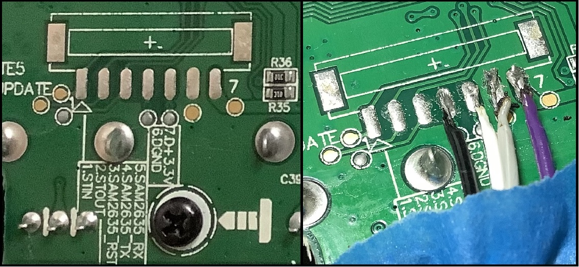
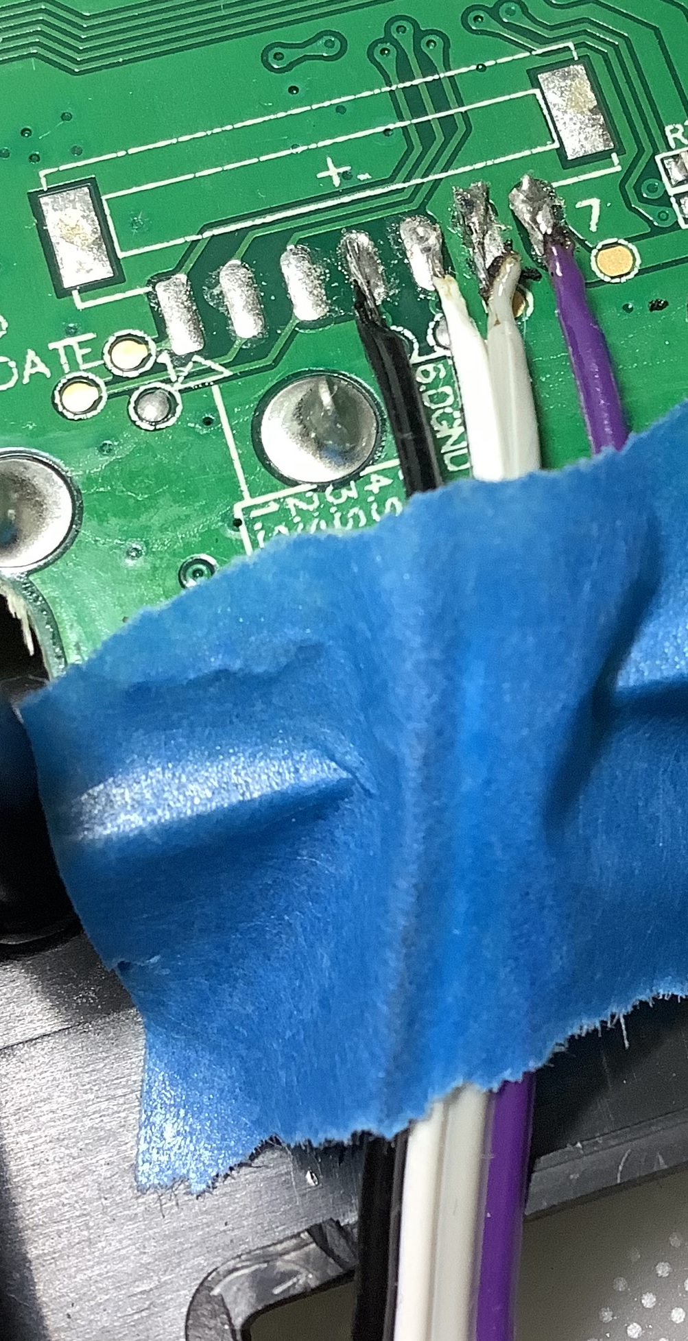
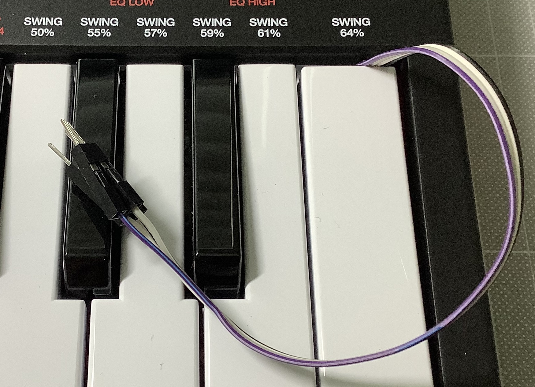
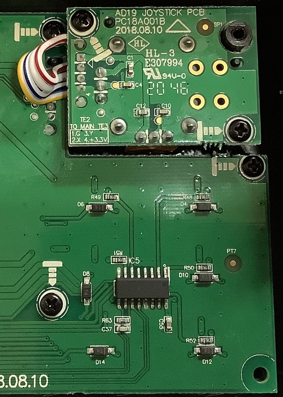
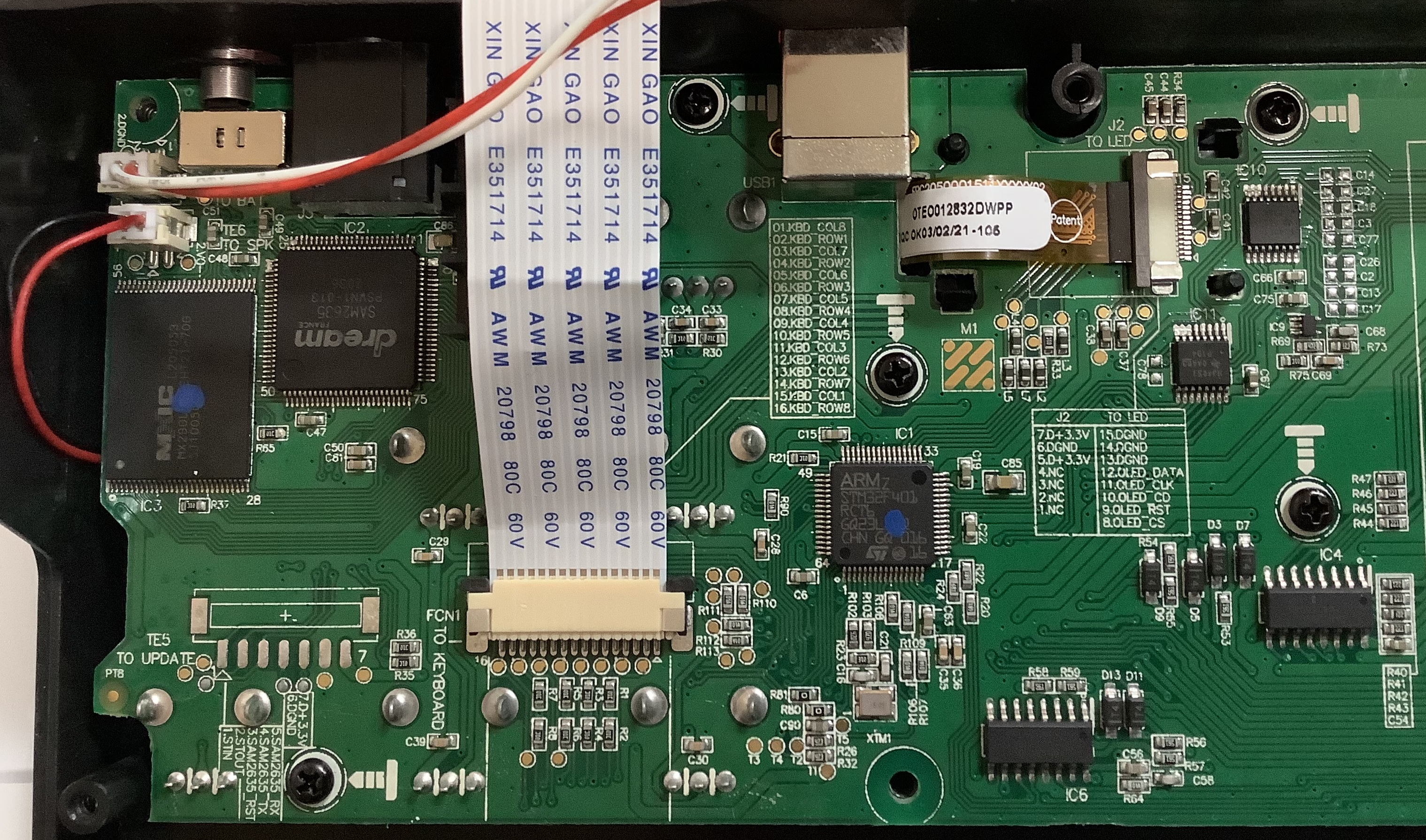
The second post, in particular, shows how I brought the internal MIDI signals out from the main printed circuit board.

For the moment, I am focused on the communication between the Arm microcontroller and the Dream S.A.S. SAM2635 synthesis chip:

            Arm       TX  ----> MIDI IN (RX)     Dream 
Microcontroller SAM2635
USART RX <---- MIDI OUT (TX) Synthesizer

The Arm microcontroller sends MIDI messages to the SAM2635. For this round of analysis, Mini Play INTERNAL SOUNDS are turned ON. A future post will address the case when INTERNAL SOUNDS are turned OFF.

When INTERNAL SOUNDS are enabled, the key strikes, pad hits, knob turns and joystick movements cause the Arm software to transmit MIDI messages to the SAM2635. These MIDI messages are encoded for and are meaningful to the SAM2635. They are not the same as the messages sent through the USB port, i.e., the user-defined MIDI CCs, etc. (USB messages are sent when INTERNAL SOUNDS are OFF.)

Persistence leads to discovery

At the end of my second post, I noted my failure to monitor the message traffic from the Arm to the SAM2635. I performed additional experiments which eventually paid off.

First, I observed the signal from Arm TX to the SAM2635 MIDI IN (RX) pin using a Gabotronics Xminilab USB oscilloscope and logic analyzer. I tried the Gabotronics protocol sniffer. Unfortunately, the Gabotronics protocol sniffer does not support the standard MIDI baud rate, 31,250 baud. The SAM2635 can communicate MIDI at 31,250, 34,800 and 200,000 baud. The 200,000 baud rate is reserved for USB debug, so it’s use is unlikely in this case. The protocol sniffer displayed HEX gibberish at 34,800.

I switched the Gabotronics to logic analyzer mode and observed the serial data signal. Yes, I found data and the data are repeatable, i.e., hit a C on the keyboard and you get the same bit sequence every time.

I estimated 8 serial bits per oscilloscope time division (256 usec). Do the math and the data rate is 31,250. The MIDI is there; I just need to sense it properly.

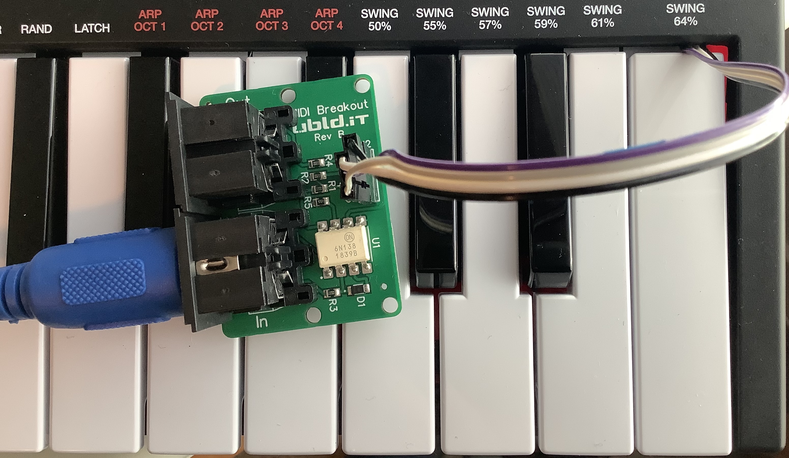
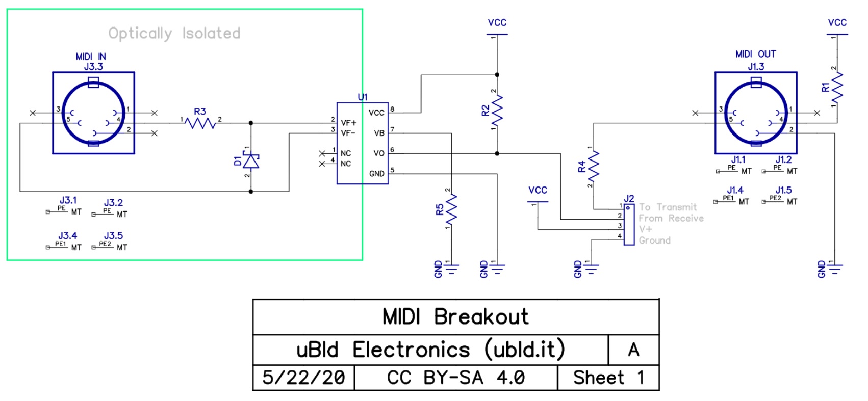
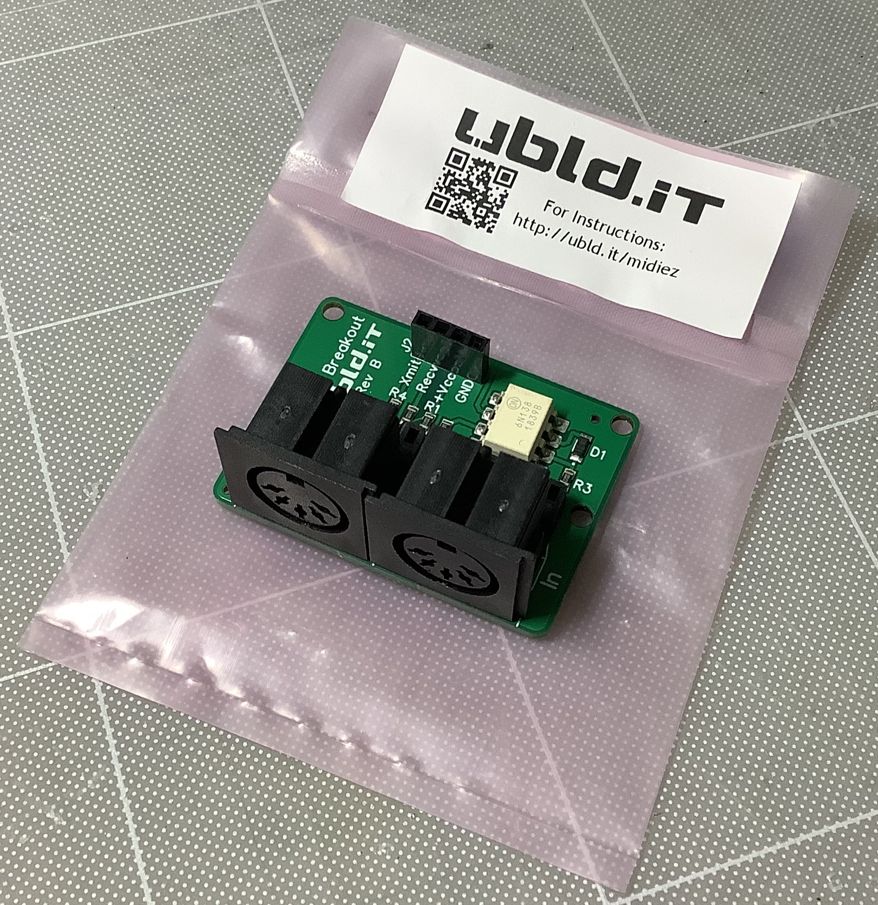
I connected the MIDI signal to the MIDI OUT side of the UBLD.IT MIDI breakout board. I sent MIDI from the UBLD.IT to the Genos MIDI IN port. Success! The Akai Mini Play can play notes and change patches on the Genos.

Instead of monitoring the MIDI message stream via MIDI-OX on a Windows PC, I used the LOG display in the MIDI Designer app on iPad. The MIDI interface in this case is an old IK Multimedia iRig MIDI. Success, again! Now I can see the MIDI messages and, indeed, they are targeted for SAM2635.

I can only surmise that my Roland (Edirol) UM-2EX MIDI interface cannot detect the signal transmitted by the UBLD.IT. I couldn’t get a Sparkfun breakout board to work with the UM-2EX either. If I want to use MIDI-OX on PC for monitoring, I’ll need to try another USB MIDI interface (perhaps my old EMU).

SAM2635 message summary

Well, franky, that’s all good news. Here is a short summary of the MIDI messages that I observed. The Akai Mini Play sends a flurry of messages to the SAM2635 when power is first turned on.

Program change also causes a flurry of messages to be sent. Here is an example program change:

B0 01 00                        CC#1 Modulation wheel 
E0 00 40 Pitch bend (center)
F0 7F 7F 04 01 00 7F F7 GM Master volume
B0 0B 7F CC#11 Expression
B0 4A 66 CC#74 TVF cutoff frequency
B0 5B 0E CC#91 Reverb send level
B0 47 00 CC#71 TVF resonance
B0 5D 00 CC#93 Chorus send level
B0 49 00 CC#73 Envelope attack time
B0 48 38 CC#72 Envelope release time
B0 63 37 B0 62 00 B0 06 48 Equalizer low band
B0 63 37 B0 62 03 B0 06 40 Equalizer high band

Some set-up messages are duplicated. I’ve seen this kind of behavior in other synths and sequencers.

Key hits, knob turns, and pad hits produce the following MIDI messages:

Gesture    Example message             SAM2635 Function 
--------- -------------------------- ---------------------------
Key hit: 90 3C 7F Note on, channel 1
80 3C 00 Note off, channel 1
Filter: B0 4A 43 CC#74 TVF cutoff frequency
Resonance: B0 47 00 CC#71 TVF resonance
Reverb: B0 5B 23 CC#91 Reverb send level
Chorus: B0 5D 00 CC#93 Chorus send level
Attack: B0 49 00 CC#73 Envelope attack time
Release: B0 48 38 CC#72 Envelope release time
EQ Low: B0 63 37 B0 62 00 B0 06 47 Equalizer low band
EQ High: B0 63 37 B0 62 03 B0 06 40 Equalizer high band
Pad hit: 99 2E 6C Note on, channel 10
89 2E 00 Note off, channel 10
Volume: F0 7F 7F 04 01 00 7E F7 GM Master volume

No surprises other than volume. I didn’t expect the front panel volume knob to send a GM Master volume message. Volume must be regulated digitally in the synth as opposed to an analog audio pot.

Copyright © 2022 Paul J. Drongowski

Akai MPK Mini Play MIDI mod (1)

Yesterday, I took a quick look inside the Akai MPK Mini Play MIDI controller and synthesizer. I would like to discover a way to drive fully the Dream S.A.S. SAM2635 synthesizer chip without interference by the Arm microcontroller.

My initial investigation concentrated on the set of test points connected to key SAM2695 inputs and outputs:

    Pad Signal        Dream function 
--- ----------- ---------------------------
1 STIN Serial test input
2 STOUT Serial test output
3 SAM2635_RST Master reset and power down
4 SAM2635_TX MIDI OUT
5 SAM2635_RX MIDI IN
6 D GND Digital ground
7 D +3.3V Digital +3.3V

If I can read and drive the SAM2635 MIDI IN and OUT, it should be possible to control the Dream synthesizer directly.

First, I need easy access to the relevant test points. I started with a 4-wire ribbon cable with male prototyping pins at both ends. These ribbon cables are easy to find and are generally used to connect a group of signals from one prototyping connector to another. In this case, I cut off the pins at one end with the intention of soldering the wires to the test points on the Mini Play main printed circuit board.

Ribbon cable to Akai Mini Play test points

The picture above shows the test points after soldering. The soldering job ain’t pretty, but the joints are functional. The color coded connections are:

    Pad Signal        Dream function  Color 
--- ----------- -------------- -----
4 SAM2635_TX MIDI OUT Black
5 SAM2635_RX MIDI IN White
6 D GND Digital ground Grey
7 D +3.3V Digital +3.3V Purple

After inspection, I took a deep breath and powered up. The Mini Play functioned correctly, thank goodness.

Ribbon cable and prototyping pins

I created a small, unobtrusive notch in the plastic top panel and routed the ribbon cable through the gap above the high C key. If I ever go to sell or trade the Mini Play, I should be able to unsolder and remove the cable while leaving the case visibly intact. As you can see in the picture above, the ribbon cable terminates at four male prototyping pins.

UBLD.IT MIDI breakout board

Next up, I assembled a UBLD.IT MIDI breakout board and interface. I bought the UBLD.IT board from Amazon. Unfortunately, the board is now out of stock. Bummer, cuz it’s a nice one.

The UBLD.IT has a 4-pin female header:

    Pin   Function 
---- --------------
Xmit MIDI OUT
Recv MIDI IN
Vcc Positive voltage rail
GND Ground

I connected the ribbon cable to the UBLD.IT board and connected the UBLD.IT to a Windows PC through a 5-pin Roland MIDI interface.

Power up. No joy. The Mini Play worked properly, but I wasn’t able to monitor the MIDI traffic from the Arm microcontroller to the Dream SAM2635 synthesizer via MIDI-OX. Nor was I able to drive the SAM2635. So much for the quickest and dirtiest solution!

Since nothing smoked and the Mini Play is healthy, it’s time for methodical investigation. First goal, I would really like to monitor the MIDI traffic from the Arm to the SAM2635. It might help me figure out what the heck the Akai software is doing to incoming USB MIDI messages. Once I ace this problem, I’ll try driving the SAM2635, again.

One further observation. I attached SAM2635_RX and SAM2635_TX to a Gabotronics USB oscilloscope. After futzing with the scope controls, I observed what looks like serial data bytes (MIDI) on the SAM2635_RX line. The Arm drives this line when it sends MIDI messages to the SAM2635. Serial bytes are sent in response to note ON/OFF, control knobs, and the joystick. Ooooo, so close!

By golly, there ought to be a way to monitor this MIDI traffic! I conjecture that the logic signal is inverted. Another possibility is a non-standard data rate, that is, something other than 31,250 baud. Probably ought to test the UBLD.IT in isolation, too.

Copyright © 2022 Paul J. Drongowski

Inside Akai MPK Mini Play (mk1)

Akai MPK Mini Play (first generation). Let’s take a look inside.

The Akai MPK Mini Play splays open just like an Akai MPK Mini. Check out one of the fine MPK Mini disassembly videos if you want to crack open your MPK Mini Play. Here are a few quick tips:

  • Gently remove the knobs from the pots. You will need to pry under each knob with a super small screwdriver or some other flat blade.
  • You need to remove the red rubber cap from the center of the joystick. The rubber cap is held on by adhesive.
  • Once the red rubber cap is removed, unscrew the joystick knob and set it aside along with the cap.
  • Remove all twelve screws from the bottom. These screws hold the bottom to the top.
  • Pry up the back of the Mini Play first and expect to sneak the top past the underside of the keys.
  • Mind the ribbon and battery cables when opening the chassis. Be slow and gentle. Do not aggressively flip the case open!

Splaying the case is good enough to expose the main electronics. Unless you are going to fix or mod the pads, you do not need to remove the main printed circuit board (PCB).

Akai Mini Play (Mk1) splayed open

As you can see in the picture, the keybed is mounted on the bottom tray. The battery compartment is molded into the bottom. A ribbon cable connects the keybed switch matrix (rows and columns) to the main PCB. In the future, I’d like to personalize my Mini Play by replacing the standard black on white keybed with a white on black keybed — Vox Continental envy. 🙂

The main PCB has left, middle and right parts. The middle looks empty, but the rhythm pads are on the other side in this region. The rubbery black pad in the case bottom provides mechanical support to the PCB beneath the rhythm pads.

Akai Mini Play main PCB joystick

The right part of the main PCB has the arpeggiator switches and joystick subassembly. The legend on the integrated circuit (IC) is super faint and is barely readable with a strong light and magnifying glass. IC5 appears to be a CMOS 595D 8-bit serial-in, serial- or parallel-out shift register. Signals from the right part of the PCB travel over a gazillion traces to the left part.

Akai Mini Play PCB (Arm and Dream synthesizer)

All the really fun stuff is on the left part of the main PCB. Here you will find the back panel components: battery/USB power switch, 3.5mm headphone jack, sustain pedal jack, and USB-B port. The sustain pedal jack is hidden beneath the ribbon cable in the picture. [You’re not really missing anything.]

The ribbon cable near the USB-B connector connects the OLED display to the main PCB. IC10 and IC11 are TI HJ4051 8:1 multiplexer/demultiplexers. Akai conveniently printed cable signal tables on the PCB. Signals for the OLED display (J2) are:

     Pin Signal       Pin Signal 
--- --------- --- ---------
1 NC 8 OLED_CS
2 NC 9 OLED_RST
3 NC 10 OLED_CD
4 NC 11 OLED_CLK
5 D +3.3V 12 OLED_DATA
6 D GND 13 D GND
7 D +3.3V 14 D GND
15 D GND

The legends on IC4 and IC5 are quite faint. They are either 74HC595D or 74HC395D. My eyes are old and sore. 🙂 This logic is probably related to the rhythm pads and signals from the right side of the main PCB.

Signal assignments are given for the keybed ribbon cable (FCN1):

     Pin Signal       Pin Signal 
--- --------- --- ---------
1 KBD_COL8 9 KBD_COL4
2 KBD_ROW1 10 KBD_ROW5
3 KBD_COL7 11 KBD_COL3
4 KBD_ROW2 12 KBD_ROW6
5 KBD_COL6 13 KBD_COL2
6 KBD_ROW3 14 KBD_ROW7
7 KBD_COL5 15 KBD_COL1
8 KBD_ROW4 16 KBD_ROW8

Typical key scanning drives a row (or column) signal and reads back a column (or row) group. Holy smokes! The Mini Play PCB may support eight groups of eight keys. If the proper software support is implemented, one might be able to attach a 61-key keybed to the main PCB! (A big “IF”.)

The 64 pin surface mount (SMT) device near the two printed tables is the main CPU: an ST Microelectronics STM32F401RCT6 Arm Cortex-M4 microcontroller. This device has a single core, 64KB RAM and 256KB flash memory. The blue dot may indicate that the device was programmed before installation. (Dunno.) I can’t read the top of the crystal XTIM1, so I don’t know the clock speed.

Finally, we get to the synthesizer (IC2): a Dream S.A.S. SAM2635. The Macronix IC (IC3) at the left edge of the PCB is NOR flash containing the Dream waveforms. Again, the blue dot may signify preload status. Near the SAM2635, we find JST connectors for the battery and the speaker.

In my view, the most exciting and interesting part of the main board are the test points in the lower left corner. The signals are:

    Pad Signal        Dream function 
--- ----------- ---------------------------
1 STIN Serial test input
2 STOUT Serial test output
3 SAM2635_RST Master reset and power down
4 SAM2635_TX MIDI OUT
5 SAM2635_RX MIDI IN
6 D GND Digital ground
7 D +3.3V Digital +3.3V

I verified these connections using a continuity tester. The SAM2635_RX and SAM2635_TX pads are connected to the Arm microcontroller:

    Pin  Function       Test POINT  Pad 
--- ------------ ---------- ---
42 USART1_TX SAM2635_RX 5 I/O 5V tolerant
43 USART1_RX SAM2635_TX 4 I/O 5V tolerant

So, boys and girls, we may be in business!

In my opinion, Akai botched the MPK Mini Play by hiding the Dream synthesizer behind software on the Arm. The Arm makes the Mini Play look like a semi-crazed synth of its own, not the SAM2635. The test points may — may — provide a way to get at the Dream synthesizer directly. The INTERNAL SOUNDS button acts like a MIDI LOCAL CONTROL button. So, I’m hoping to disable internal sounds and hijack the MIDI IN and OUT test pads (signals) to the SAM2635.

Come for the teardown; Stay for the mods:

Copyright © 2022 Paul J. Drongowski

Review: Akai MPK Mini Play (Mk1)

Now that Akai have introduced the new Akai MPK Mini Play Mk3, original first generation Mini Plays are going on sale. Being a notorious bottom-feeder (doing the most with the least), I cashed in a few loyalty points and bought one.

First generation Akai Mini Play (Mk1)

Sound On Sound magazine recently reviewed the new mk3. Many of their comments apply to the original MPK Mini Play; basic functionality has not changed. The mk3 includes an improved second generation MPK Mini keybed, a bigger and better speaker, a different panel layout and different, narrower pads. Everything else is pretty much the same. Having an OLED in an inexpensive product like the MPK Mini Play is a luxury.

For the el cheapo price, the MPK Mini Play is surprisingly well-made. The keyboard and knobs don’t feel cheap although I doubt if they are very durable. All of the back connectors are mounted directly on the main printed circuit board (PCB) and should be treated with respect and care. There are numerous USB connector repair videos on-line (for the similar Akai MPK Mini), so beware when handling any of the Minis.

As to the Mk3 improvements, I get it. The original’s speaker is quite weak with limited frequency range. The original keybed is a little touchy. Keys need to be struck firmly to reliably trigger notes. One cannot play soft notes; forget nuance. The pads aren’t bad, however. Pads have always been Akai’s strong point.

The sound engine is the Dream S.A.S. SAM2635 with its 8MByte CleanWave® soundset. The Mini Play’s soundset has 128 General MIDI sounds, 9 drum sets and one sound effects (SFX) set. By and large, it’s a decent sounding GM set including the reverb and chorus. The front panel knobs let you tweak filter cut-off, resonance, attack time, release time, reverb level, chorus level, EQ low and EQ high. Edits can be saved to one of eight Favorite locations. In this regard, the Mini Play is one-up on the Yamaha PSS-A50. (The PSS-A50 price is in the same neighborhood as the Mini Play.)

That’s the good news. Now the bad news. As mentioned in the Sound On Sound review, the incoming MIDI implementation is a nightmare. [I’m still figuring it out.] Foremost, the Akai Mini Play is not a multi-timbral GM module. The Akai software modifies (filters? blocks? mangles?) whatever MIDI you send to it before it sends its own internal MIDI stream to the SAM2635.

This is a shame and a lost opportunity for Akai and its customers. The Mini Play could be so much more if it allowed a direct path to the SAM2635. The Dream firmware is a complete GM/GS implementation. WTF, Akai? Akai would sell shed-loads more if the Mini Play was an actual GM module.

I’ve encountered Dream synthesis before in the Modern Device Fluxamasynth and the midiPlus miniEngine USB. Unlike the Akai, both devices suffer from noisy audio. I’m doubly disappointed because the Mini Play audio is relatively clean.

So, if you’re looking for a DAW-driven synth module, pass on both the original and Mk3.

As to the outgoing MIDI implementation — using the Mini Play as a controller — it is basic and functions well. The free software editor gives you access to everything configurable (pads, knobs and joystick), storing configurations into a Favorites slot. No complaints here although MPK Mini users might miss the four additional knobs provided by the plain ole Mini.

The Akai MPK Minis are the gateway drug to MPC production. Akai have always rolled out good value with their bundles. The Mini Play software bundle follows the path and includes:

  • Akai VIP VST instrument and effect host environment
  • AIR Hybrid 3 synthesizer
  • Wobble synthesizer
  • MPC Essentials (AKA tons of samples)
  • ProTools | First

And, of course, Akai’s free MPC Beats application. Download and installation, if you go for everything, is laborious due to partnership arrangements and different authorization and licensing procedures.

Bottomline. A MIDI module it is not. If you want a tiny, inexpensive MIDI controller with a limited in-built synthesizer and a serious stack of content, give it a go. If you expect to play live, go for the Mk3 and the better keybed and speaker.

After initial disappointment about the MIDI implementation, I took a screwdriver to the MPK Mini Play. Naturally, a device this small and inexpensive is mod fodder. I will discuss mod potential in a future post.

Update: If you intend to use the Akai MPK Mini Play as a MIDI module, you must read my analysis of its MIDI implementation. If you want to mod the MPK Mini Play, start here and here.

Like the review? Check out the teardown (disassembly) and mods:

Copyright © 2022 Paul J. Drongowski