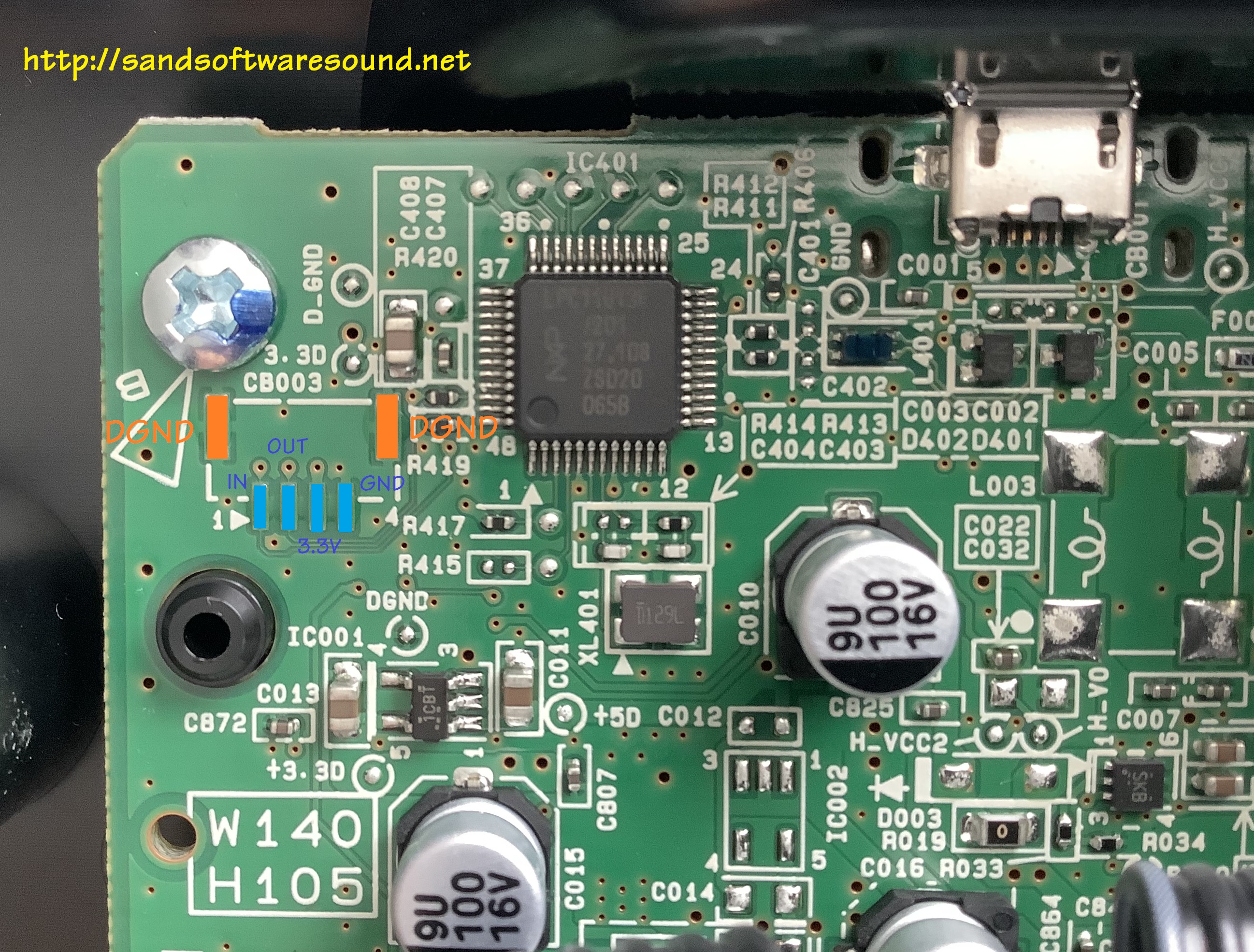
There are a set of test pads in the upper left corner of the A50 main board (DM) as shown in the picture below. [Click image to enlarge it.]
Yamaha PSS-A40 MIDI signals and USB circuitry
The two larger rectangular pads (orange) are digital ground (DGND). The four smaller pads (blue) from left to right are:
MIDI_IN (RXD MIDI_IN)
MIDI_OUT (TXD MIDI_OUT)
3.3V
Digital ground
The blogger connected the MIDI_OUT signal to a 5-pin DIN connector, which is mounted nearby on the enclosure.
By the way, Yamaha conveniently mark test points with a circle (bullseye). You can see several test points for digital ground (DGND), the +3.3V digital rail, and the +5V digital rail. The USB interface chip is an NXP ARM microprocessor. The micro USB connector is in the upper right.
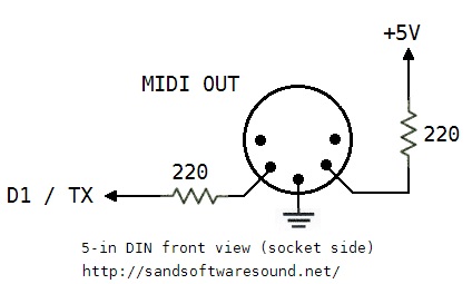
Direct connection is too trusting. The MIDI_IN and MIDI_OUT pads go directly to SWLL pin 55 (RXD) and SWLL pin 54 (TXD). I suggest adding a 220 ohm current limiting resistor in series with MIDI_OUT. Adding a signal buffer would be even better since you would rather blow up the buffer instead of the main processor (YMW830-V or SWLL) should someone radically misconnect the 5-pin MIDI port. A current limiting resistor on the +V MIDI pin wouldn’t hurt either.
Simple MIDI OUT circuit
If you get the urge to add 5-pin MIDI IN, you’ll need an optoisolator as shown in the schematic below.
Simple MIDI IN circuit
Although the schematics indicate 5V, the circuits should work with 3.3V instead. Fortunately, the unpopulated test connector provides +3.3V as well as MIDI_IN and MIDI_OUT.
Here’s an idea. Instead of hacking in a 5-pin DIN connector alone, why not add a Bluetooth MIDI plug like the CME WIDI Master?
Our Japanese blogger considered adding a sustain input. The PSR-F50 dedicates SWLL pin 53 (PORTC0) to sustain. Unfortunately, the PSS-A50 has other ideas and SWLL pin 53 mutes the headphone output instead. You could put an external switch in parallel with the front panel sustain switch, but it toggles sustain and, thus, it doesn’t behave like a true piano sustain pedal.
As with any mods, make them at your own risk and kiss your warranty good-bye!
Yamaha have had a busy few years updating their entry-level models, most notably, the PSR-E373 and the DGX-670. We have yet to see the PSR-E473 and PSR-EW425 models which will replace the PSR-E463 and PSR-EW410, respectively.
No doubt, supply chain and global shipping problems have delayed product launch. Prior PSR-E4xx models employ digital-to-analog converters (DAC) including DACs from Asahi Kasei Microdevices (AKM). The AKM plant in Nobeoka city suffered a major fire on October 20, 2020. Japanese authorities just recently gave AKM permission to clean-up and rebuild. The AKM fire caused a mass shortage of its digital-to-analog and analog-to-digital converters. The shortage affects other major audio and digital musical instrument manufacturers, too, not just Yamaha.
In addition, Yamaha is ramping up production at its new OneHub Chennai (India) manufacturing plant. The Chennai plant products acoustic guitars and portable keyboards for the Indian market and for export. According to a May 2019 press release, the initial goal is to make 200,000 acoustic guitars and 150,000 portable keyboards, including the PSR-I500 and the PSS series. Yamaha eventually wants to raise the goal to 400,000 acoustic guitars and 300,000 keyboards per year. Roughly 50% of production will be for export.
My PSS-A50 was manufactured in India. Given kinship to the PSR-I500, I would expect Chennai to make the new PSR-E473 and PSR-EW425. Export data indicate that a few E473s already have been run off and exported. Prototypes? Development? Testing?
Of course, the delayed launch has intensified interest among enthusiasts. The E373 received substantial feature upgrades: Super Articulation Lite (S.Art Lite) voices and new DSP effect types which once could only be found on mid- and upper-range arrangers. A few of the new effects are top-of-the-line: dual rotary speaker, Real Distortion guitar amp effects, vintage stereo phaser, compression and harmonic enhancer. One fully expects to see the same upgrades in the E473 and EW425.
S.Art Lite voices behave somewhat differently than their mid- and upper-level cousins. A dedicated articulation button triggers the articulation effect. The cousins transparently employ software scripting which reacts to player gestures, e.g., legato, intervals, and so forth.
Is this the new Yamaha PSR-EW425?
My first thought was “That looks quite professional,” not just a home keyboard. The live control knobs are re-located to the upper left. This decision will be controversial! The lighted buttons look pleasant (light blue color) and the screen is black and white monochrome. Still only four registrations per bank.
Yamaha did majorly swizzle around a bunch of front panel controls with respect to the E463. The keypad to the right has been significantly redesigned.
The quadrant to the right of the display has a 3×4 button matrix for voice and style selection by category. The buttons above the data wheel control selection mode: voice or style. I wonder if one of the mode buttons turns the matrix into a numeric keypad? The FUNCTION and PORTABLE GRAND buttons are below the matrix along with some kind of BOOST button.
The control groups running above the keyboard are (left to right): master volume, SONG/STYLE control, TRACK control, registration memory, and quick sampling. The large light blue button between the volume knob and the SONG/STYLE control group may be the ARTICULATION button.
The Quick Sampling feature got more real estate. Quick Sampling has several buttons: LOOP HOLD, A, B, C, D, and CAPTURE. I wonder if it’s possible to capture four waveforms? Did Yamaha re-think sample control including sample zones? Do the lighted A, B, C, D buttons reflect sample status like a pad controller? Can we play the pads? Are they velocity sensitive?
The live control knobs are further away from the keyboard in the quadrant to the left of the display. I can’t tell if there is an additional row or not. E463 has five live control rows; EW425 has 6 or 7?
The rest of the buttons in the upper left quadrant must be record, metronome, tap tempo, melody suppressor, voice control and all that miscellaneous stuff. The legends in the picture are too distorted to read.
Yamaha is still using an LCD with pre-defined, fixed icons and legends. Do they really save that much money versus a full graphic, pixel addressable display? What do I know? It probably simplifies the software, but it seems so 90s.
Should be interesting finally to see the specs, and not just guess.
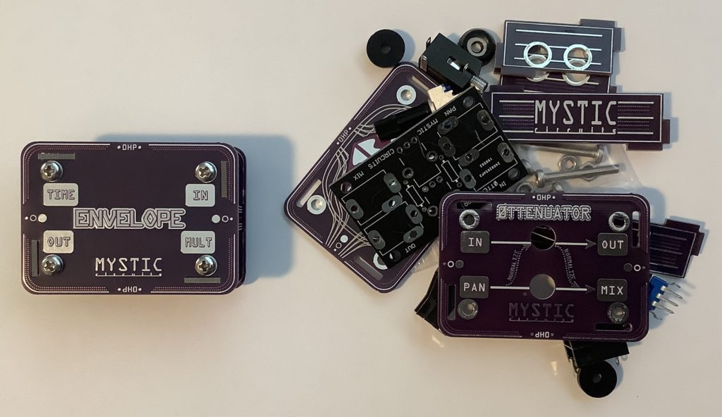
As promised, here is a review of the Mystic Circuits 0HP Envelope module. I won’t go through build details, etc., since I discussed these aspects of the 0HP line in my review of the Mystic Circuits 0HP 0ttenuator.
Mystic Circuits 0HP Envelope and 0ttenuator modules
The 0HP modules all share the same micro form factor. The 0HP Envelope has four jacks:
IN: Gate or audio input
MULT: Duplicates the IN signal for patches
TIME: Release time control voltage (CV) input
OUT: Envelope output
Given a gate signal, the 0HP Envelope module generates a simple envelope. Given an audio signal, the Envelope module is an envelope follower, i.e., it generates an envelope which tracks the audio amplitude.
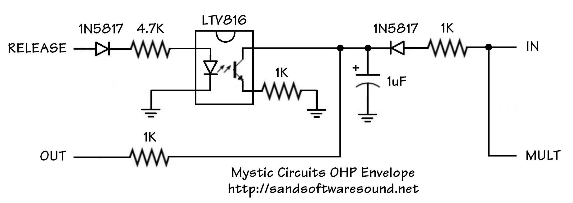
Schematic
Mystic Circuits have not posted a schematic for the 0HP Envelope. So, I drew one up. [Click images to enlarge.]
Mystic Circuits 0HP Envelope schematic
The 1uF capacitor is key to understanding the Envelope’s operation. The IN signal charges the 1uF capacitor while the phototransistor in the optoisolator (KTV816) discharges the capacitor to ground. The charge on the capacitor determines the OUT voltage. If you put audio into the Envelope, the capacitor smooths out the audio, leaving only the amplitude envelope.
The (release) TIME signal controls the brightness of the LED in the optoisolator. The brightness then controls the gate of the phototransistor. When the LED is brighter, the gate turns ON harder, more current flows, and the capacitor discharges faster.
I connected the output of a Yamaha PSS-A50 to the audio input of the littleBits Filter. I sent the audio — in parallel — to the IN jack of the 0HP Envelope. No joy, or at least, not much happiness. I could not discern an audible difference in the filter cut-off sweep.
This minor failure motivated a few quick experiments to better understand the 0HP Envelope.
Oscilloscope: Audio envelope follower
When puzzled, measure!
Keeping the PSS-A50 as my audio source, I monitored the incoming audio signal and outgoing envelope using a Gabotronics USB oscilloscope.
The 0HP Envelope is, essentially, a passive device. It doesn’t require power and it doesn’t have any active electronics to amplify the incoming audio (or gate) signal. The phototransistor in the optoisolator acts like a variable resistor. Thus, what comes out of the envelope depends on what goes into it.
I immediately had to crank the oscilloscope gain to compensate for the small peak-to-peak audio signal going into the 0HP Envelope. The audio signal from the PSS-A50 does not have much voltage swing. The incoming signal limits the sweep of the outgoing envelope signal.
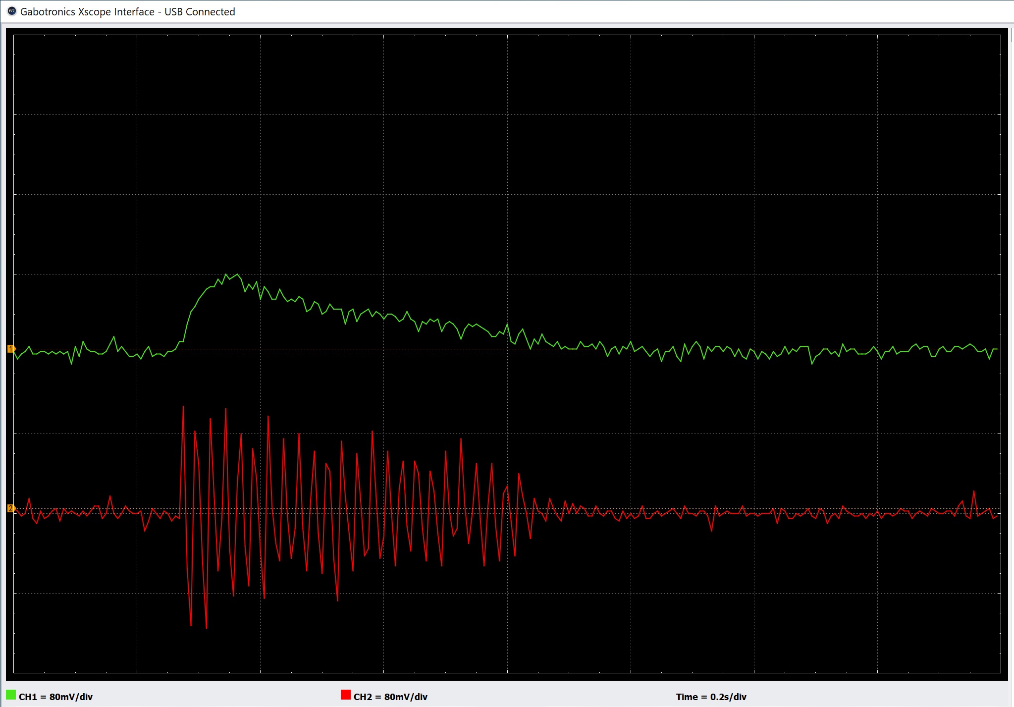
Envelope (top) and piano note (bottom)
The oscilloscope traces above are a short piano note and the envelope produced by the 0HP Envelope module. Please note the voltage per grid unit; it’s very small. The small peak-to-peak audio signal does not produce a very large envelope voltage swing. The small swing was probably not enough to produce an audible filter cut-off sweep in the littleBits case.
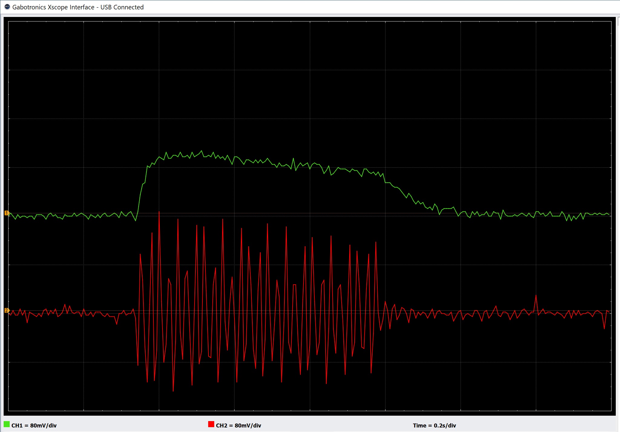
The oscilloscope traces below are an oboe note and its envelope.
Envelope (top) and oboe note (bottom)
The traces look quite noisy thanks to the high oscilloscope gain. I suspect that some noise is to due to the crummy USB ground from the PC.
Oscilloscope: Gated envelope
To verify my hypothesis concerning signal level in affecting signal level out, I connected the Arturia Keystep Gate output to the 0HP Envelope module and monitored both the gate and envelope signals with the oscilloscope.
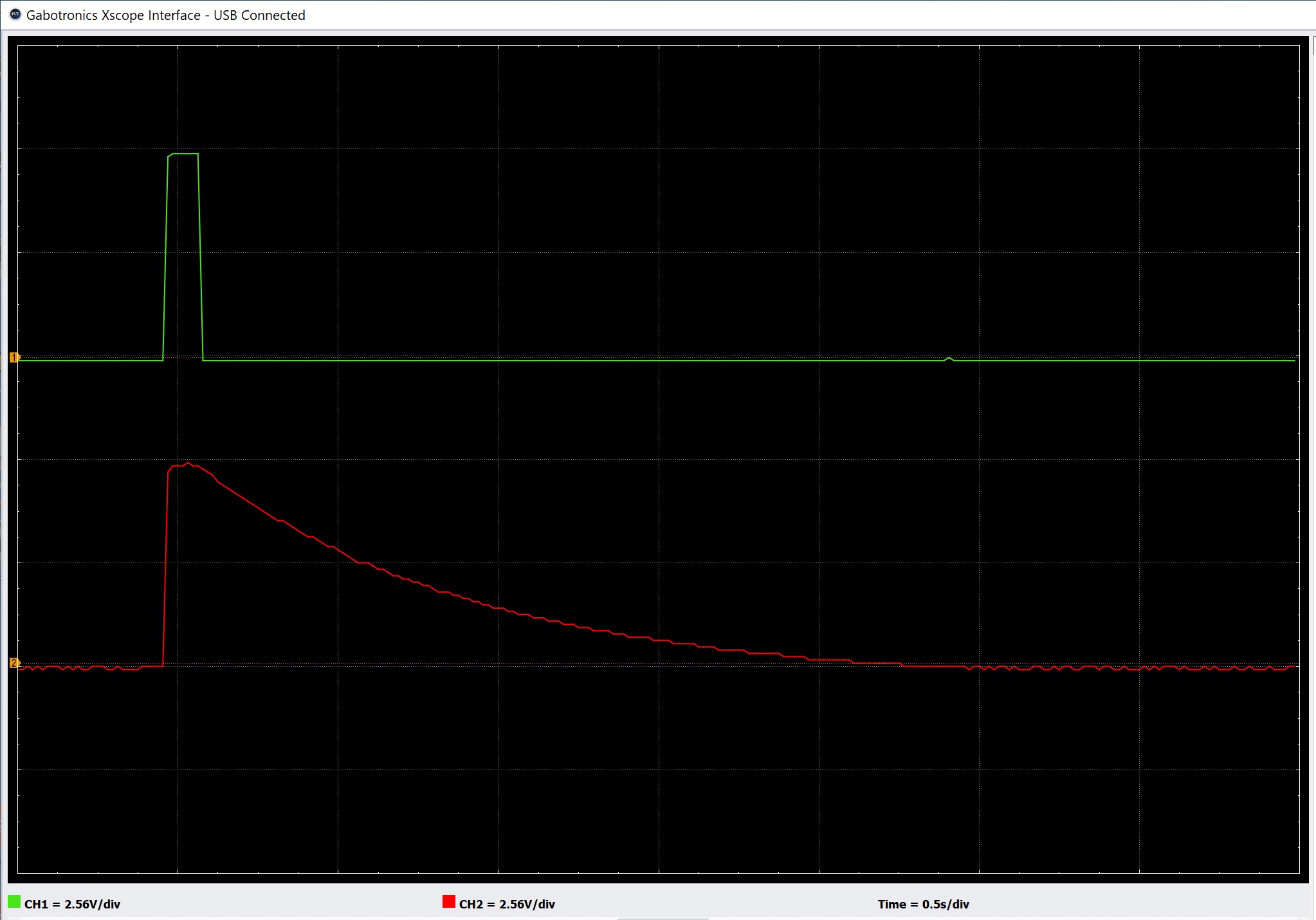
Short gate (top) and envelope (bottom)
As expected, I needed to adjust the oscilloscope gain down to accommodate the relatively higher gate voltage. Given a strong gate signal, the envelope swing is much wider as shown in the oscilloscope traces above.
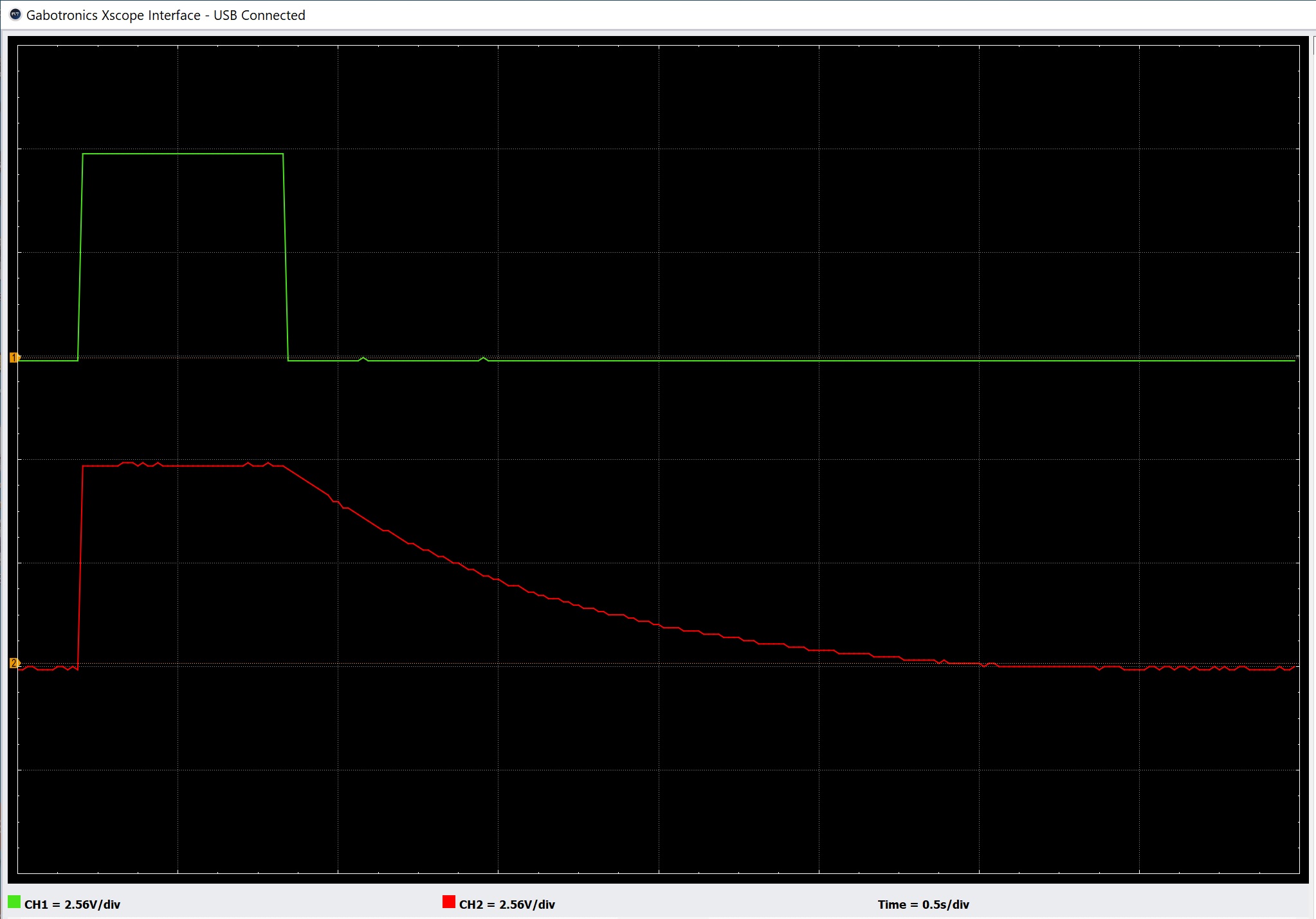
The 0HP Envelope stays high while gate is asserted. The example below shows the envelope produced by a longer note. When the TIME input is unused (0 Volts), the release time is rather long. You will most likely need to adjust the release time in practice unless you want a long release!
Envelope (bottom) stays high while gate (top) is high
Summary
Overall, the 0HP Envelope does what Mystic says. It’s a reasonable envelope generator (or follower) as long as you understand its behavior: big signal in, big signal out; small signal in, small signal out.
Here are further notes taken from the Mystic Circuits video about the 0HP Envelope.
When driven with a Gate, the Envelope will stay ON while the Gate is high. Then it will slowly release to zero when the Gate goes low.
Release time is controlled by the RELEASE control voltage (CV) input. With no control voltage going into RELEASE, the Envelope release time is at its longest. Release time decreases as a positive CV is applied. When driven with audio, the Envelope will give you a voltage which is proportional to the amplitude of the incoming audio. Sensitivity is controlled by the RELEASE CV input. When driven with a variable voltage, the Envelope will glide when the input voltage falls. It will increase quickly when the input voltage rises. Glide time is controlled by the RELEASE CV input. This only works on positive voltages.
The Envelope module has an on-board MULT to the input which allows chaining of multiple units. This is useful when you want to use an active envelope generator to produce more complex shapes and use the 0HP to produce simpler shapes. You can also route incoming audio back into your patch.
I discovered Mystic Circuits while browsing Patchwerks. Mystic Circuits make and distribute a line of analog synthesis modules including its “0HP” micro-modules. Time to take a look.
But, first. Patchwerks? Patchwerks was a great little find, too, and a synthesizer lifeline during the pandemic. Patchwerks has a small Seattle-based brick-and-mortar retail store as well as its Web store. I have yet to step into their physical store, but I have ordered a number of small boards and toys on-line. Each time, their fulfillment has been fantastic: good packaging, same day shipping and quite frequently, over-night delivery, thanks to our Seattle metro locations. Watch for their seasonal sales. Highly recommended!
Mystic Circuits assembled and kit
The 0H modules get their name because they don’t take up space in your modular rack. Each module implements one or more utility and synthesis functions that don’t require a rack slot. Just patch ’em in. Mystic Circuits offer 0HP modules both fully assembled and in kit form. Initially, I was searching for an envelope follower block and in the course of that search, I discovered the entire 0HP product line. I bought the 0HP Envelope module (fully assembled $36USD) and the 0ttenuator module (kit form $18USD). I focus on the 0ttentuator in today’s post.
Mystic Circuits 0HP 0ttenuator
The 0HP 0ttenuator is one of those modules that you can’t live without. It performs four functions:
Single passive signal attenuator
Dual, independent passive signal attenuators
Two input passive mixer
One-to-two signal splitter
I can’t count the number of times when I needed a simple signal attenuator (e.g., knocking a headphone level down to LINE), or a 2-input mono mixer. The 0ttenuator does the job and then some.
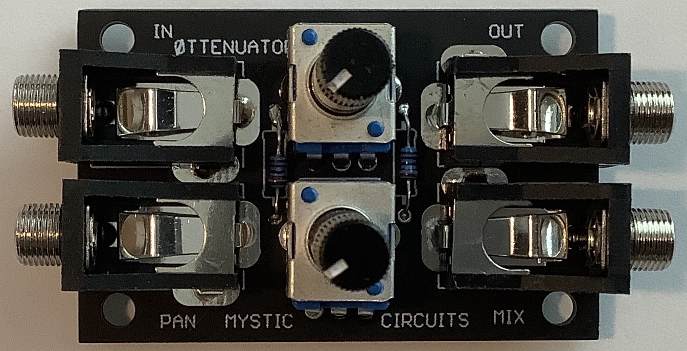
Mystic Circuits 0ttenuator PCB (top)
Even though Mystic Circuits call it the “simplest kit,” I wouldn’t recommend it for beginners. The resistor pads are really dinky and it would be easy to make a solder bridge to other, larger pads. You need a really good soldering tip to nail it. I suggest checking your work with a magnifying glass. Further, Mystic don’t identify the resistor values (or color codes). The resistors are so small, I can’t accurately read the color bars! Whip out a digital meter and the resistors measure as 22K ohms. The potentiometers (B104) are 100K ohms.
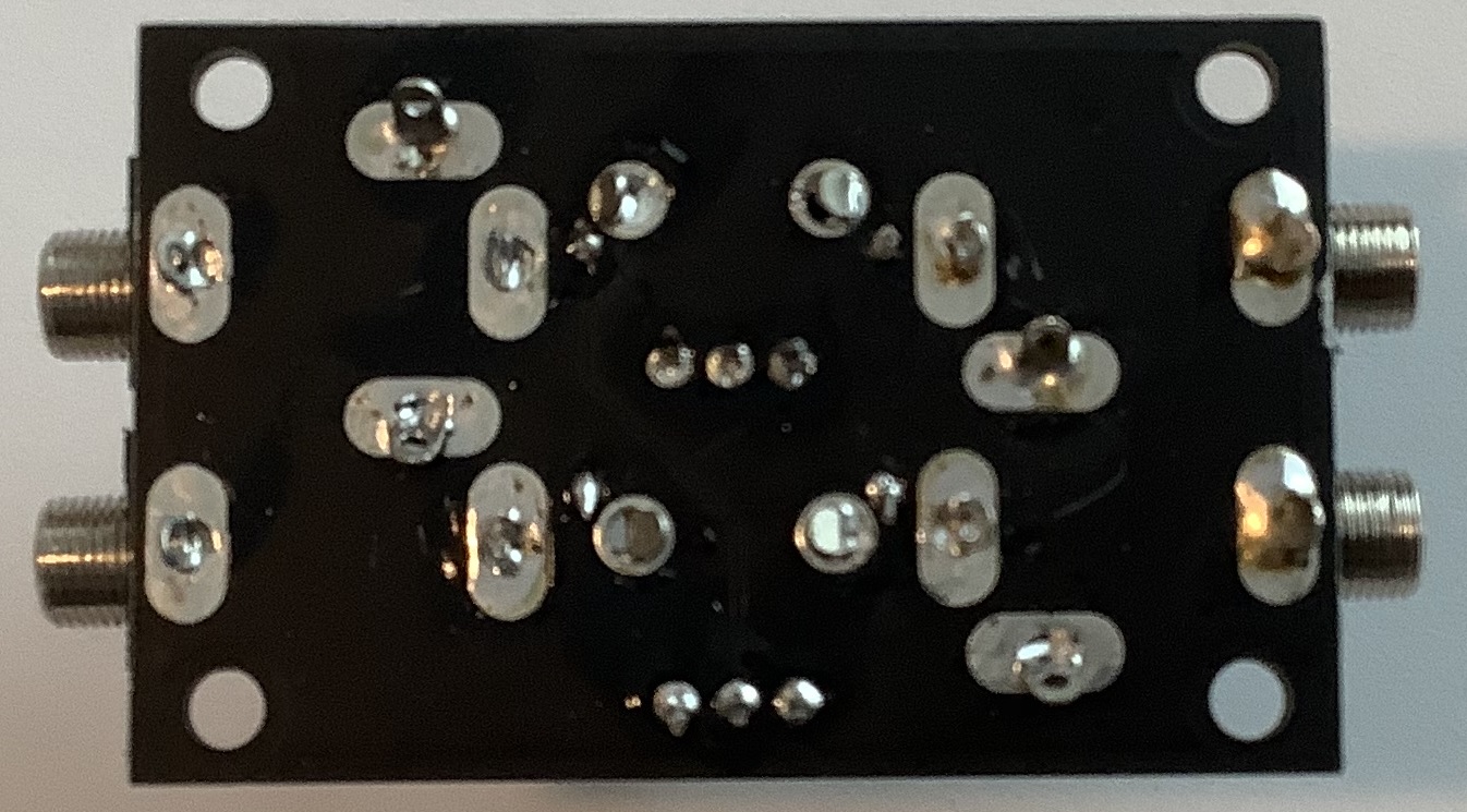
Mystic Circuits 0ttenuator PCB (bottom)
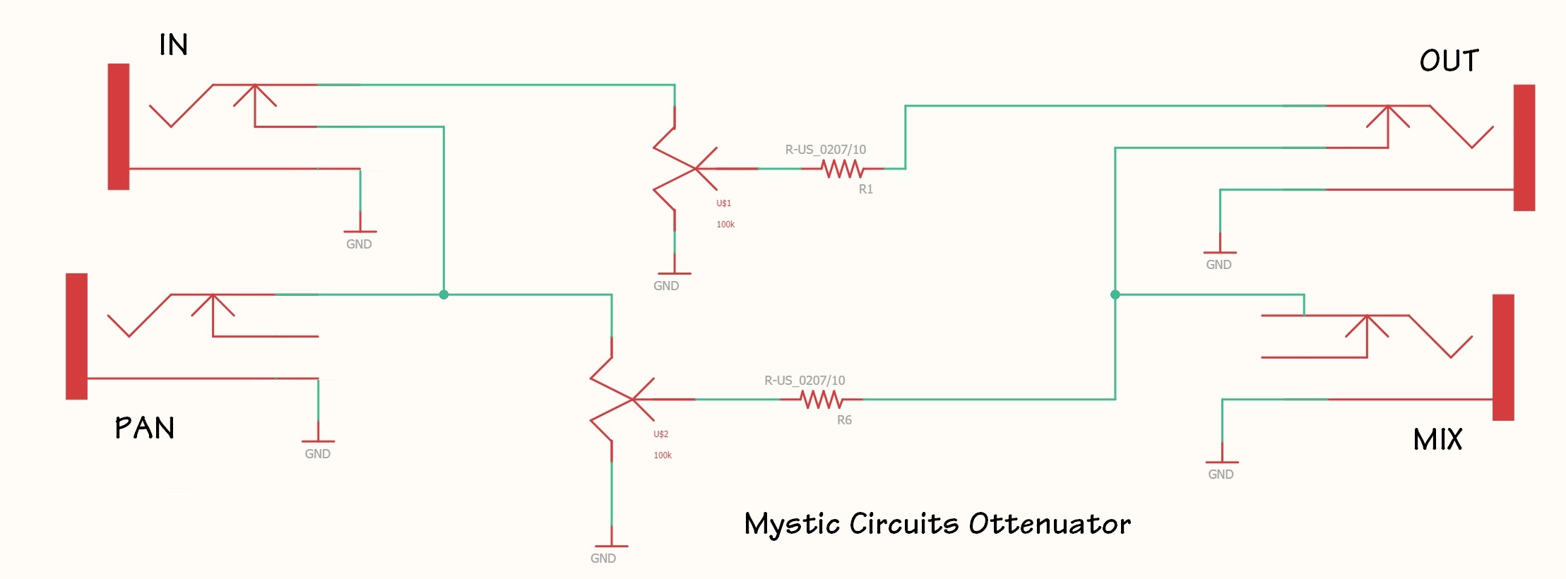
If I have to ding Mytic Circuits, I find their documentation to be thin and sketchy. Useful information is buried in video, including build and operating instructions. Nothing is written down. Frankly, I don’t have time to watch a video when I can read bullet points in a few seconds. Although Mystic provide Eagle “sch” files on their github site, most people aren’t set up to display Eagle. I ran the sch file through schematics.io and captured the rendering (below).
Mystic Circuits 0ttenuator schematic
Hey, I’ve seen this circuit somewhere before! Nonetheless, it’s a very flexible design and the 0HP module is well-made. Operation depends upon the switched input jacks which configure the circuit for attenuation, mixing and splitting.
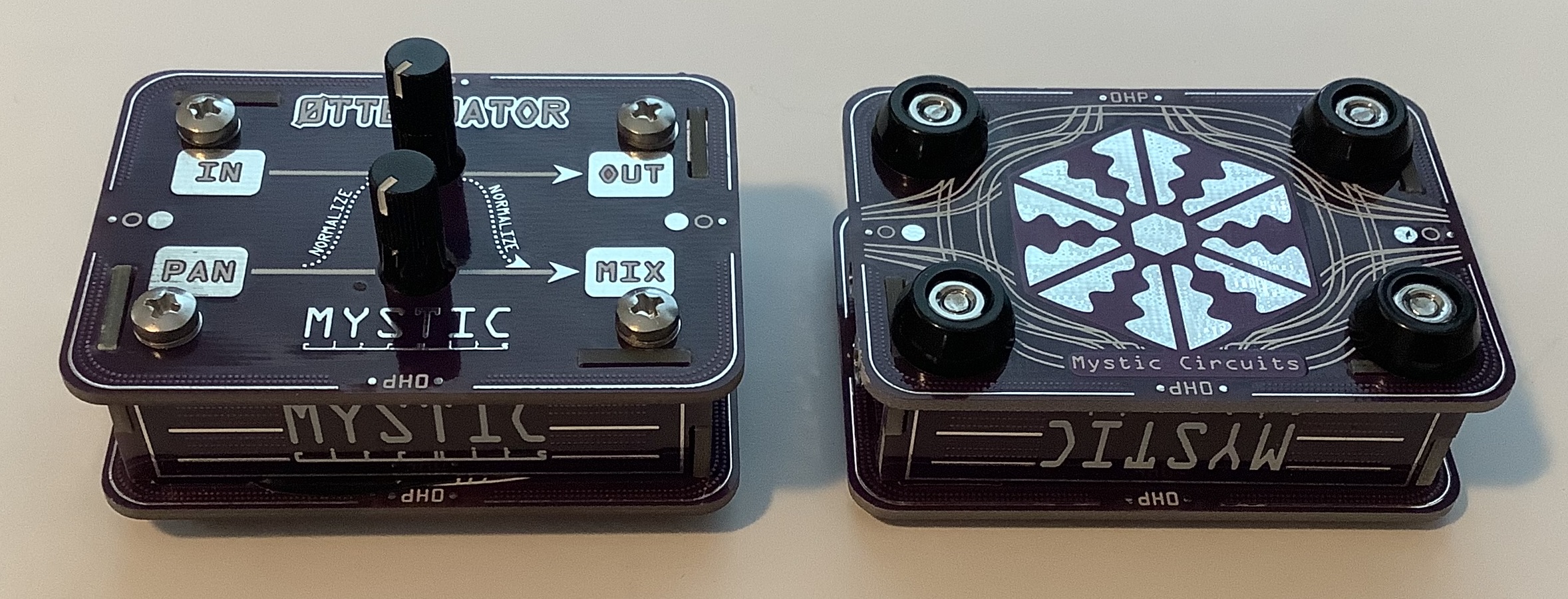
Mystic Circuits 0HP case top and bottom (assembled)
I’m glad that I purchased a fully assembled Envelope module along with the 0ttentuator kit. The fully assembled module showed me how to assemble the case. Again, the Mystic Circuits site does not have instructions for assembling the new 0HP cases. The video build instructions show the old plexiglass covers and spacers, not the new PCB-ish case. That’s the drawback of putting everything in videos; if the product changes, it’s a pain to revise the existing videos to reflect product changes.
The final niggle has to do with the metallic graphic design on the case bottom. I fear it will make unwanted contact with the bottom of the printed circuit board (PCB). I put a thin layer of electrical tape over the inner surface of the bottom case cover. (The design is etched onto both sides of the case bottom.)
If you buy a 0HP 0ttentuator module — and I recommend it — here are the missing operating instructions:
To use one attenuator:
Plug incoming signal into IN jack
Plug outgoing signal into OUT jack
Turn knob to change signal level
To send an incoming signal to two places:
Plug incoming signal into PAN jack
Plug one outgoing lead into the OUT jack
Plug the other outgoing lead into the MIX jack
Use knobs to set outgoing levels
To mix two signals together:
Plug one incoming signal into the IN jack
Plug the other incoming signal into the PAN jack
Plug the outgoing lead into the MIX jack
Use knobs to set the outgoing level
To use each attenuator separately:
Plug first signal into the IN jack and the corresponding output lead into the OUT jack
Plug second signal into the PAN jack and the corresponding output lead into the MIX jack
Use knobs to set levels for each separate signal
Mystic Circuits 0HP Envelope
I want to test the 0HP Envelope with a littleBits Filter. Given time constraints, I’ll address that subject in a future blog. In the meantime, here is a little more information about the 0HP Envelope.
Here is a description of the 0HP Envelope, paraphrased from the Mystic Circuits video.
When driven with a Gate, the Envelope will stay ON while the Gate is high. Then it will slowly release to zero when the Gate goes low. Release time is controlled by the RELEASE control voltage (CV) input. With no control voltage going into RELEASE, the Envelope release time is at its longest. Release time decreases as a positive CV is applied.
When driven with audio, the Envelope will give you a voltage which is proportional to the amplitude of the incoming audio. Sensitivity is controlled by the RELEASE CV input. When driven with a variable voltage, the Envelope will glide when the input voltage falls. It will increase quickly when the input voltage rises. Glide time is controlled by the RELEASE CV input. This only works on positive voltages.
The Envelope module has an on-board MULT to the input which allows chaining of multiple units. This is useful when you want to use an active envelope generator to produce more complex shapes and use the 0HP to produce simpler shapes. You can also route incoming audio back into your patch.
Unfortunately, the Mystic Circuits github area does not have an Eagle schematic. So, I drew one (shown below). Hope I got it right!
Mystic Circuits 0HP Envelope schematic
The 1uF capacitor is key to understanding the Envelope’s operation. The IN signal charges the 1uF capacitor while the phototransistor in the optoisolator (LTV816) discharges the capacitor to ground. The charge on the capacitor determines the OUT voltage. If you put audio into the Envelope, the capacitor smooths out the audio, leaving only the amplitude envelope.
The RELEASE signal controls the brightness of the LED in the optoisolator. The brightness controls the gate of the phototransistor. When the LED is brighter, the gate turns ON harder, more current flows, and the capacitor discharges faster.