Sparkfun Danger Shield

Sparkfun is one of my favorite companies. I like their products and their service is very good and reliable. I’ve learned a lot by studying their designs and I especially like their commitment to education.

Previously, I built two Sparkfun kits: the Redboard PTH Arduino and the MIDI break-out board. I have several more kits on hand to satisfy the occasional urge to solder!

Recently, I built a Sparkfun Danger Shield, hoping to use it as part of a MIDI drawbar controller. The code for the controller is still a work in progress. So, in the meantime, here is a micro-review of the Danger Shield.

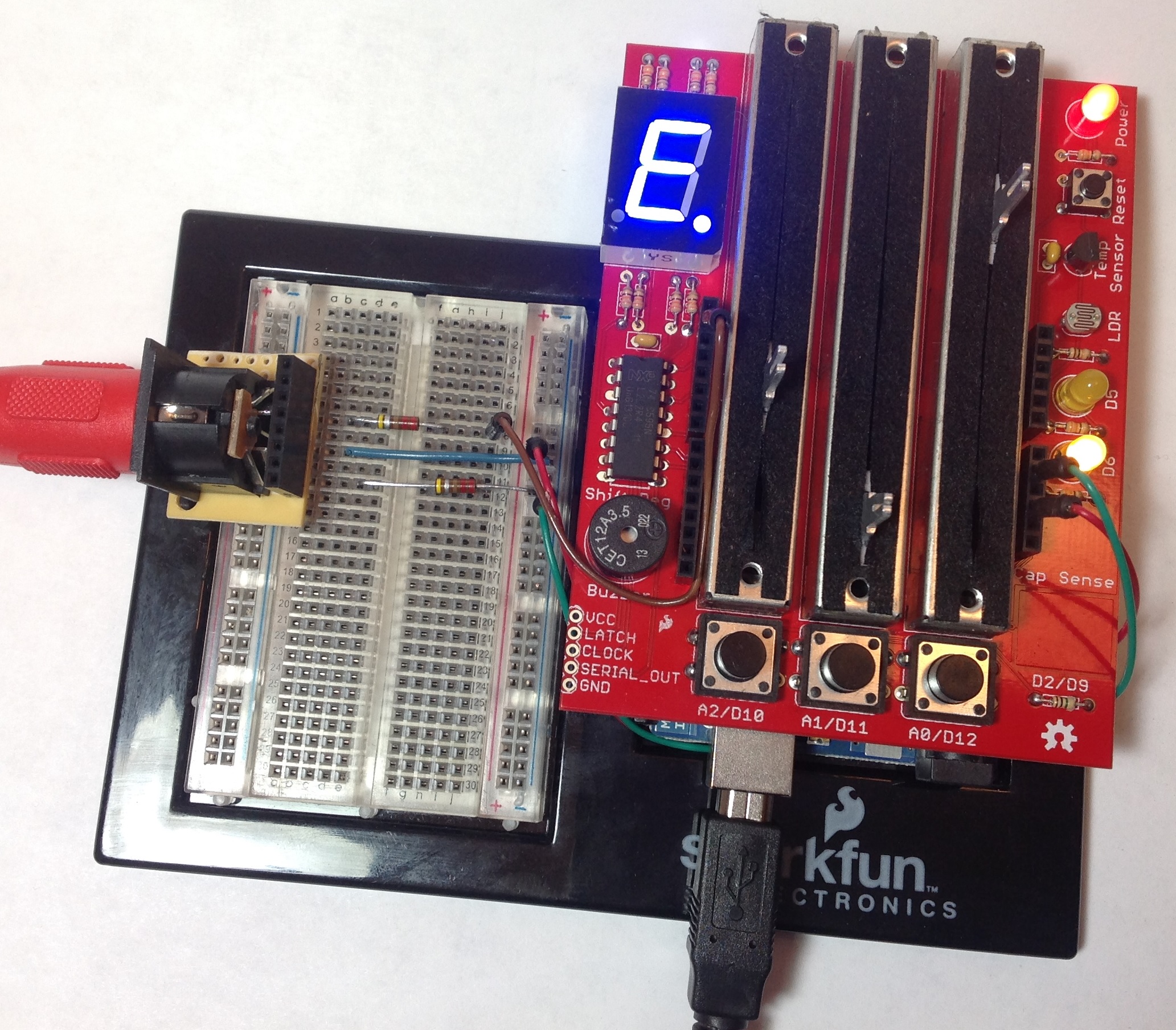
The Danger Shield is a “jack of all trades” for input to an Arduino. It has three large sliders, three momentary contact buttons, one temperature sensor, one light sensor, and a capacitive touch sensor. The Danger Shield also provides basic output/display capability, too. The shield has two yellow LEDs, a seven-segment display, and a buzzer. For the MIDI controller project, I’m mainly interested in the sliders, buttons, LEDs and seven-segment display. However, I can see some creative possibilities for the other sensors in MIDI control.

Kit assembly went quite well, taking about two hours total. I think that a beginner could put one together without too much trouble. There was only one minor hang-up. The on-line assembly instructions are out-of-date. Two decoupling capacitors were added to the design after the instructions were published. One capacitor is mounted near the temperature sensor and the other capacitor is mounted near the shift register integrated circuit. This could trip up a beginner since they will have two small parts left over if they simply follow directions!

DangerShield

Sparkfun thoughtfully provide an Arduino Sketch (program) to test the sliders, buttons, etc. This is a great idea and I wish that more companies provided test programs with their products. When you build a kit, you really want to know if everything works before you design the kit into an experiment or prototype. Unfortunately, the test program expects the cap sense code to be installed as an IDE library. This dependency could trip up a beginner since they would need to learn how to install library code before running the test program. Since I didn’t intend to use the cap sense pad right away, I commented out the cap sense code and tested everything else.

The one thing that surprised me is the physical size of the shield. It is much bigger than the standard Arduino footprint. I had originally intended to stack the Danger Shield, the MIDI break-out board and the Arduino on a Liquidware side-by-side extender. This approach would have saved me the effort of whipping up a 5-pin MIDI OUT port. Unfortunately, the large size of the Danger Shield prevents much stacking.

I decided to prototype on an Arduino UNO which is installed on a plastic Arduino and breadboard holder. The Danger Shield is stacked on top of the Arduino UNO. The 5-pin MIDI OUT port resides on the breadboard. I built a 5-pin DIN break-out board to securely attach the 5-pin connector to the broadboard as well as provide a way to make necessary connections to the Arduino +5V, ground and TX pins. This quick-and-dirty break-out board should aid future experiments, too, and is a good investment of time. Finally, I wrote a quick test program to drive MIDI data through the output port and to make sure that it was electrically sound before I connect it to an expensive synthesizer or arranger workstation.

All in all, I recommend the Danger Shield. It’s possible to build a pretty decent user interface given a little bit of creative thought. The sliders and buttons are robust and should endure much abuse during testing.

MMS as a tool

I’ve got a lot more experience with the Yamaha Mobile Music Sequencer (MMS), so it’s worth passing along an update. I’ve been composing backing tracks for classic soul jazz tunes. If you would like to hear the results, please browse over to the Music Gallery.

MMS is a phrase- and section- oriented composition tool. A song is a sequence of one or more sections and a section is a group of phrases that play together. The phrases follow the section’s chord progression. Thus, it’s easy to pull a section together given a chord progression from a lead sheet and a library of drum, bass, guitar and piano phrases (MIDI loops).

This approach works great for a simple tune like “Memphis Underground.” Memphis Underground is built on a single chord (C7) and simple bass figure that repeats ad infinitum. Just set the chord progression for each section to C7 and stack drum, bass, guitar and electric piano phrases. Vary the arrangement by stacking different phrases in each section and lay down the different sections in the song. I recorded the simple flute part that makes up the head (the main melodic theme) into a phrase of its own. Finally, I recorded solo parts into the MMS song screen because it didn’t make sense to split the solos into separate phrases. Overall, this approach worked out pretty well.

Life got a little more interesting with “Watermelon Man” and “Comin’ Home Baby.” These tunes are 16- and 12-bar blues. It would be great to arrange the songs from short 4-bar phrases and just let the phrases follow the chord progression. However, when fills are placed at the end of a 4-bar phrase, the fills do not always play at the most musically appropriate points in the tune! I resolved this problem by increasing the phrase length to 8 bars. I also recorded the head into a phrase of its own. It’s handy to play back the head while stacking phrases even if you intend to record the head along with the solos in the MMS song tracks. Melodic phrases such as these must be set to by-pass transposition.

Then there are tunes like “Tough Talk” and “Put It Where You Want It.” These tunes are based on one or more musical hooks that are essential to the character of the song. Generic bass or piano phrases just don’t cut it. I had to record phrases to cover the hooks and the head. Now, on-the-fly transposition guided by the section chord progression really starts to fight you! I wound up recording full, chorus-long phrases (all 12-bars), effectively ignoring (defeating) chord transposition by the sequencer. Each section has only one chord (e.g., F7 or C7) which simply determines the key for the tune. The hook phrases must be set for “parallel” transposition.

Put It Where You Want It is a work in progress. This tune is even more complicated to sequence because it has three major sections, each with a distinctive hook and theme. Stay tuned!

Overall workflow with MMS has been good. The Mixdown feature makes it easy to create a WAV file. MIDI (SMF) export is also easy. I’m using iTunes File Sharing to move the WAV and MID files to a PC where I convert the WAV to MP3 and add General MIDI (GM) SysEx and voices to the SMF file. iTunes File Sharing is a lot less hassle than I originally anticipated. The latest version (3.1) of MMS adds Dropbox, but I haven’t updated as yet.

There is one minor recurring problem. The MMS tone generator is a subset of the Yamaha XG standard and includes extended XG drum kits. This is good for musicians who are working on XG-compatible and/or Yamaha instruments because the GM drum kit is quite limited. However, the extended MIDI notes outside of the GM range do not map to the same percussion sounds on non-XG equipment, e.g., Roland Sound Canvas. So, I have had to edit the MIDI file and remap notes to make the drum parts truly General MIDI compatible.

Workflow is essentially in one direction only. I think the software developers see MMS as a mobile sketchpad where a musician jots down ideas that are transferred to and finished on a computer-based DAW. MMS cannot import results from the DAW. So, once you start editing with your DAW (e.g., SONAR or Cubase), you’re committed.

Well, there you have it. The true worth and limitations of a software tool like MMS are only apparent when taking on complicated, real-world problems. I’m still enthusiastic about MMS, but I’m also more knowledgeable and wary of its limitations. The song/section/phrase structure can definitely fight back at times!

Tyros 4 teardown

I stumbled across this Yamaha Tyros 4 teardown on Youtube. Although the video is a little bit long-winded, you get a peek under the hood of the Tyros 4 and see a few of the circuit boards.

Unfortunately, the video is short on the kinds of details that you would find in a Yamaha service manual. I wish that the producers had taken a close pan of the main logic board with enough resolution to read the part numbers. The narrator read off the part number of the main CPU, Renesas R8A77310D, but then stated that he couldn’t find information on the web. OK, here’s the info. It’s a Renesas SH7731 processor containing an SH4AL-DSP core. The maximum clock speed of the SH7331 is 333.4MHz. The SH-4 core is a rather powerful, DSP-capable core.

The narrator also mentioned an Altera Cyclone. This is a field programmable gate array (FPGA) which probably provides some glue logic like a bus bridge. Since it’s an FPGA, it could be programmed to do just about anything.

The video shows at least two other very large scale integrated circuits. Two of these are probably SWP51 tone generators. The SWP51 has two 16-bit wave memory ports (each with separate address and data ports). Therefore, the IC package is big and has a lot of pins. The SWP51 is where Yamaha keeps the secret sauce. They have never published papers about it and with good reason; Korg, Roland and Casio would probably love to know what’s inside, too!

Given that the Tyros 4 has Vocal Harmony 2, it most likely has an SSP2 chip.

Leaving the video aside, here’s a few “big picture” thoughts.

First, it’s interesting to see how Yamaha have been riding the CPU and memory technology curves. They have used successively more powerful SH architecture CPUs over the years. They clearly have deep knowledge and competence with this architecture. Memory-wise, they have progressed from mask ROM to bulk programmable ROM (P2ROM) to NOR/NAND flash. NOR/NAND flash is so widely used in the PSR-S950, for example, that the entire machine — in theory — could be reprogrammed.

Next, if I were Yamaha, I would consider using an ARM system on a chip (SOC) in the entry level and possibly the lower mid-range keyboards. They could achieve a higher level of functional integration with ARM and still obtain low power consumption. Further, they could provide superior tone generation at the entry level. The proof point is the Yamaha Mobile Music Sequencer (MMS) app on the Apple iPad. MMS on ARM supports eight tracks of playback with a polyphonic, XG-like software tone generator. MMS provides basic XG variation effects which are not current entry-level features. Of course, this means that Yamaha is willing to leave its comfort zone with the SH architecture!

Yamaha arranger product family

Even I found the last post to be down in the weeds and confusing. So, here’s a better summary.

I went on an Internet dumpster dive over the weekend to find more service manuals for Yamaha keyboards. I’ve always been interested in the architecture of product families and curiosity got the best of me, again.

The Yamaha arranger keyboard family has four main tiers: 1. Premium, 2. Upper mid-range, 3. Lower mid-range and 4. Entry. These are my names. Each tier has its own hardware architecture. Let’s take it from the top.

Keyboard Main CPU Sub CPU Tone gen Wave ROM
Tyros 2 128MHz SH7727 200MHz SH7709S 2xSWP50 6x256Mbit
Tyros 3 128MHz SH7727 200MHz SH7206 2xSWP51B 4x512Mbit
Motif XS 400MHz TX4939 None 2xSWP51 2x512Mbit

Tyros keyboards form the premium tier. I could find service manuals for only the Tyros 2 and Tyros 3; I’ll bet that the Tyros 4 has a similar internal architecture. The Tyros has two CPUs: a main CPU to handle the user interface and peripherals (e.g., the hard disk) and a sub CPU for digital signal processing (DSP) and to manage tone generation. The main CPU bus and the sub CPU bus are connected through a bridge (implemented in gate array technology). The main and sub CPU each have their own SDRAM and program ROM. (This is true for the other tiers as well and I won’t mention it again.)

Tone generation is performed by two SWP5x integrated circuits. The SWP51 is the current series. The wave ROM is split into an upper and lower bank and is shared by the two SWP5x tone generators on a common wave memory bus. SWP51 wave ROM is dedicated to tone generation. The SWP51 implements higher waveform sample compression. Thus, the Tyros 3 actually has less physical wave ROM than the Tyros 2, even though the Tyros 3 implements memory hungry Super Articulation 2 (SA2) voices. Interestingly, there is an audio backchannel from one of the SWP51s to the hard disk subsystem. The audio data passes through an “audio transformer” circuit on its way between the SWP51 and the hard disk subsystem.

BTW, I resist making any guesses about the inner design of the new Tyros 5.

I included the Motif XS in the table for comparison. The Motif’s TX4939 is a MIPS architecture processor while the Tyros CPUs are SH-2/SH-3 architecture. (Completely incompatible, of course.) The Motif XS runs Monta Vista Linux. The tone generation architecture is very similar to the Tyros: two SWP51s and two banks of wave ROM on a shared bus.

Keyboard Main CPU Sub CPU Tone gen Wave ROM
PSR-S750 135MHz SWX08 None 1xSWP51L 2x1Gbit
PSR-S950 256MHz SH7331 SSP2 1xSWP51L 2x1Gbit
PSR-S710 128MHz SH7727 None 1xSWP51L 2x256Mbit
PSR-S910 128MHz SH7727 135MHz SWX02 1xSWP51L 2x512Mbit
TMS320DA150

The upper mid-range keyboards have a main CPU. However, only the S9xx keyboards have auxilliary processors. The older S910 has a sub CPU (SWX02) and bridge, an arrangement which is similar to Tyros. The S910’s TMS320 (Texas Instruments DSP) implements the MP3 CODEC. The S950 does not have a sub CPU. Its main CPU, however, has a much higher clock rate and probably took over the workload performed by the S910’s sub CPU and MP3 CODEC. The S950’s SSP2 processor is a Yamaha custom IC for vocal harmony processing.

Upper mid-range keyboards use one SWP51L integrated circuit for tone generation. Wave ROM is split into two banks and is connected directly to the SWP51L. Current generation keyboards (S750 and S950) make wide use of flash memory. More than ever, product features are determined by code and content alone.

Keyboard Main CPU Sub CPU Tone gen Wave ROM
PSR-S650 135MHz SWX02 None On SWX02 1x512Mbit
PSR-S550 135MHz SWX02 None On SWX02 1x256Mbit

The lower mid-range keyboards have only a main CPU: an SWX02. The SWX02 has a Renesas part number and is probably an SH architecture machine. Tone generation is integrated into the SWX02. The SWX02 has a dedicated interface to the wave ROM. The S650 has only 25% of the S750’s physical wave ROM.

Keyboard Main CPU Sub CPU Tone gen Prog/Wave ROM
PSR-E213 128MHz SWL01 None CPU 1x32Mbit
PSR-VN300 128MHz SWL01 None CPU 1x64Mbit
PSR-E403 128MHz SWL01 None CPU 1x64Mbit

The entry level keyboards are, of course, the most cost and price sensitive. The entry level keyboards can also run on battery power thereby imposing further power and performance limitations. Entry level keyboards do not provide much in the way of voice-level effects. All three of the example keyboards have a single SWL01 CPU and are all clocked at 128MHz. The ROM contains both the program and waveform data. Thus, waveform data is read across the CPU memory bus along with all of the usual program/data traffic. Physical ROM size is very much smaller then even the S550/S650. The component count is very low and the circuit boards are quite simple.