littleBits envelope generator

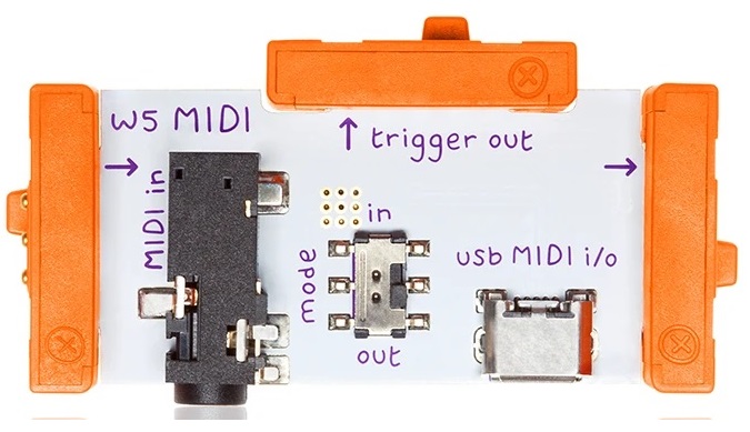
In my last post, I investigated the gated CV signal produced by the littleBits MIDI Module. Now, let’s take a look at the Envelope Module.

littleBits Envelope Module

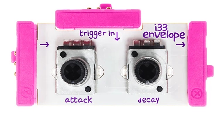
The littleBits Envelope Module is rather basic with only attack and release controls (no decay or sustain controls). The module has two inputs:

  • The primary input at the left end of the module typically receives the audio to be shaped by the envelope.
  • The trigger input receives an (alternative) trigger signal.

The Envelope Module triggers in one of two ways:

  • When the primary input transitions from zero to a positive voltage.
  • When the trigger input transitions from zero to a positive voltage, usually 5 Volts.

Allowing the primary input to trigger envelope generation simplifies connection. It is also easier to use conceptually. A beginner doesn’t need to understand envelope generators, voltage controlled amplifiers and how the two interact. A beginner doesn’t need to wire in a separate envelope generator. Everything happens along a single audio signal path and “it just works.”

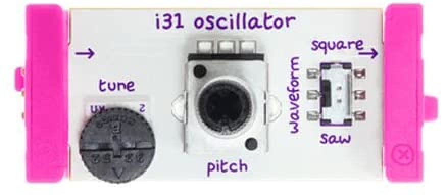
The simple circuit below is all one needs to get started with synthesis:

    Power --> MIDI --> Oscillator --> Envelope --> Speaker

If you have is the basic Synth Kit, then the MIDI Module may be replaced by the Sequencer Module or Keyboard Module. As we saw in the last post, the Gated CV output from the MIDI Module turns the oscillator ON and OFF (gate) and sets the oscillator pitch (CV). When the Oscillator is generating audio, the audio signal triggers the Envelope Module which shapes the audio amplitude. The shaped audio (now with attack and release segments) is finally sent to the speaker.

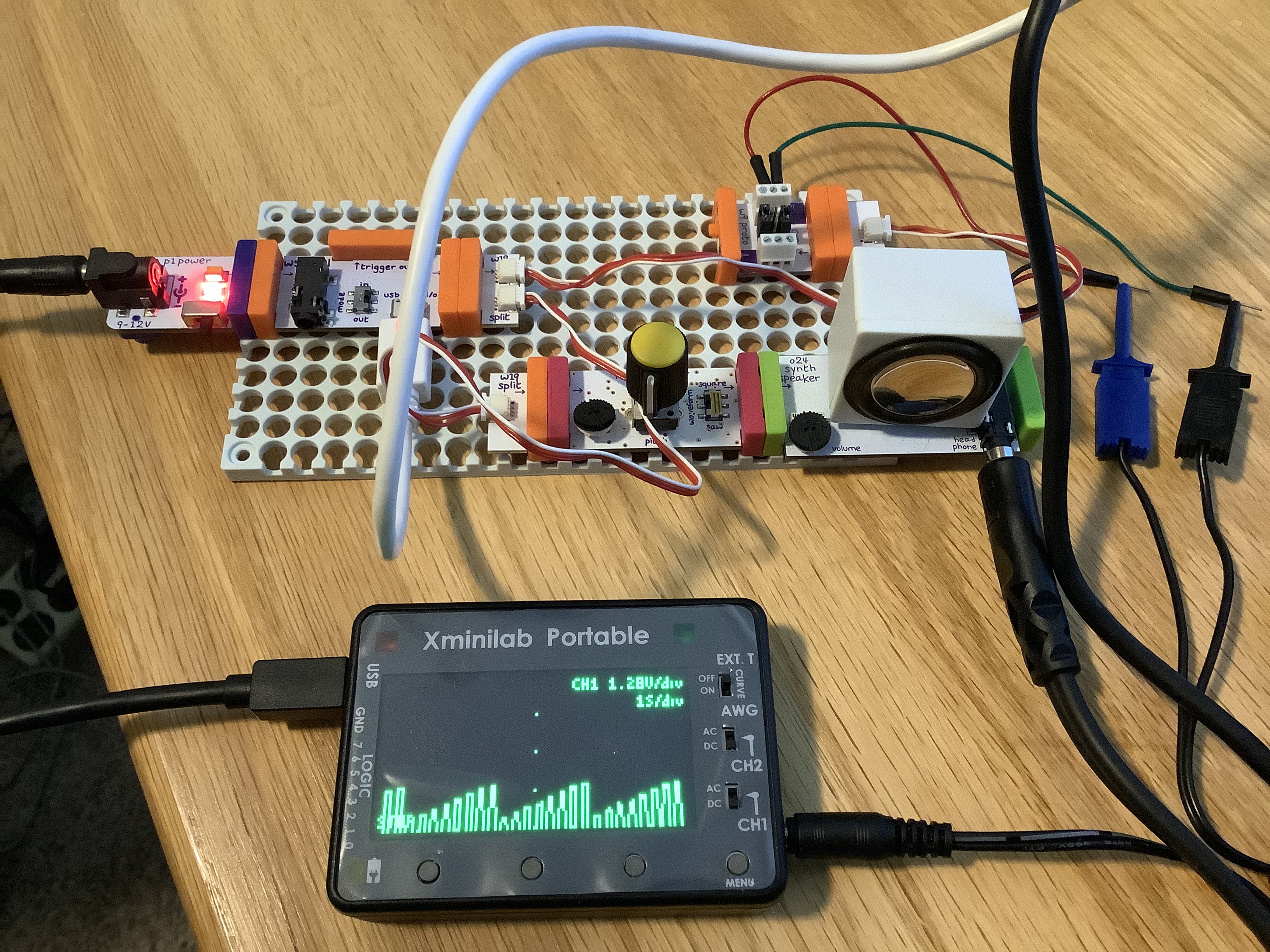
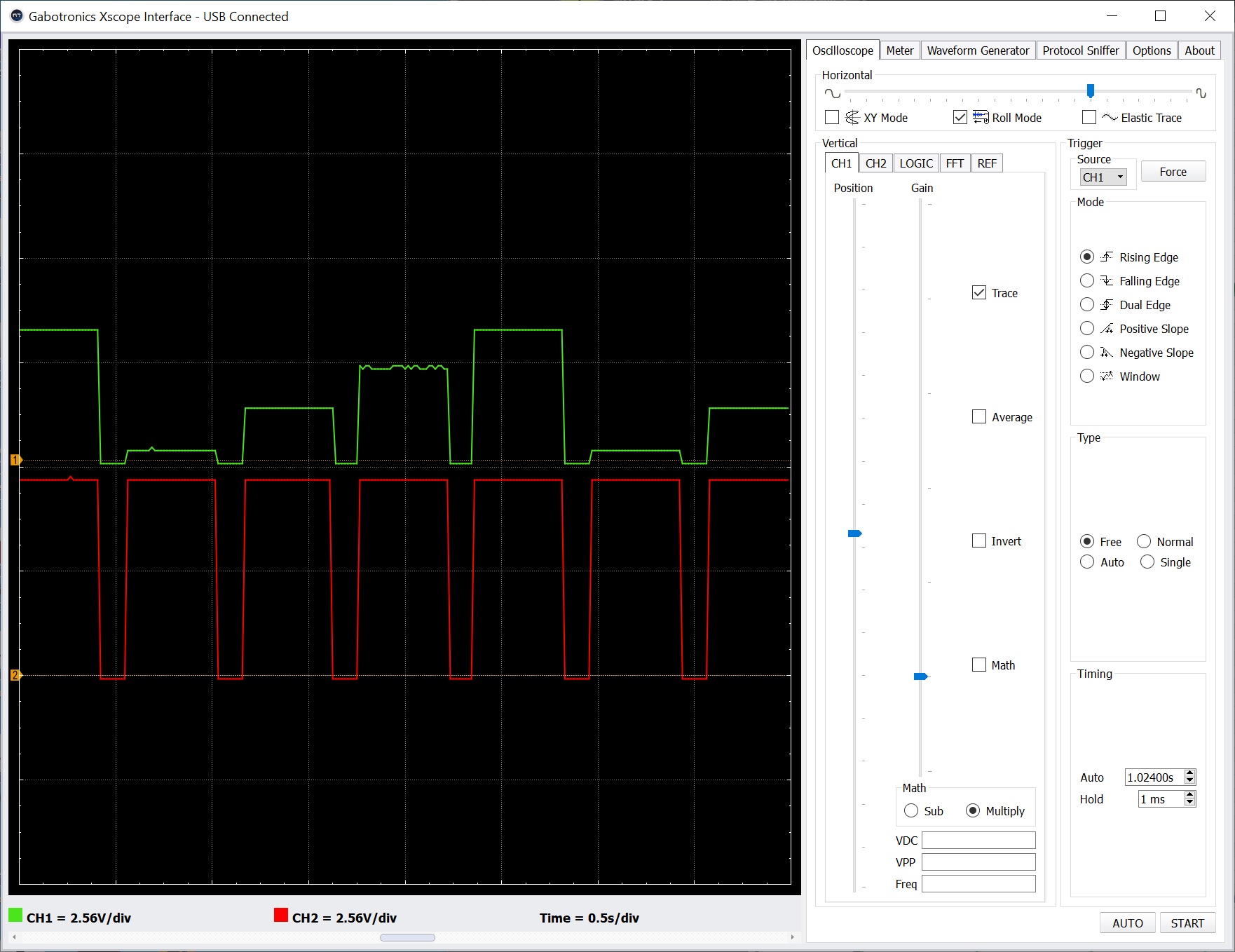
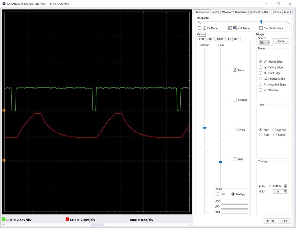
I connected this simple circuit to a dual trace oscilloscope. I found that the attack and release phases are sequential without an intervening sustain phase. The duration of the entire envelope is the sum of the attack duration and release duration. There isn’t a decay phase either. In other words, holding the gated CV longer does not sustain a note! The maximum duration of the attack phase is about 1 second and the maximum duration of the release phase is about 2 seconds.

Envelope Module in action (max attack and max release)

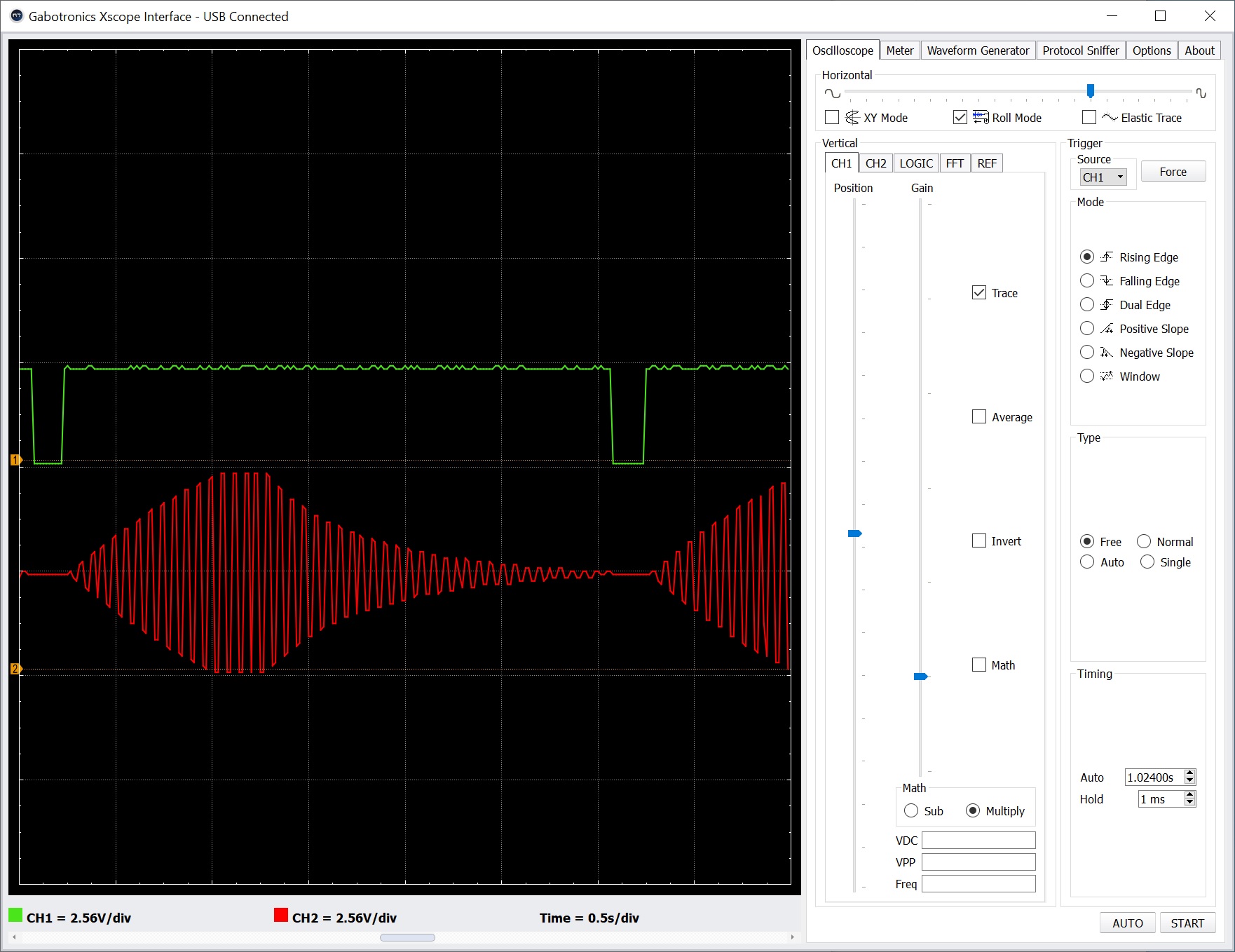
The oscilloscope traces above show the final, shaped audio signal when attack and release are set to maximum. [Click images to enlarge.] The top trace (green) is the gated CV signal from the MIDI Module. The bottom trace (red) is the shaped audio signal. Each horizontal grid mark is 0.5 seconds. Please note that the gate must be as wide as the attack duration plus the release duration to obtain the full contour.

littleBits Filter Module

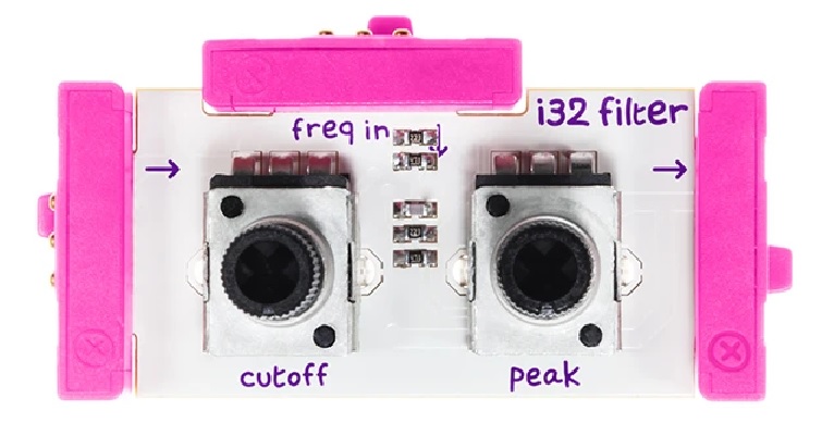
Skipping ahead to the Filter Module for a moment, the Filter has an input which allows cutoff frequency modulation. In a typical modular synth, this input is tied to a separate envelope generator. In keeping with the littleBits “It just works” philosophy, you can drive the cutoff input with the audio signal as seen in the circuit below:

                                                ---- 
| |
| V
Power --> MIDI --> Oscillator --> Envelope --> Filter --> Speaker

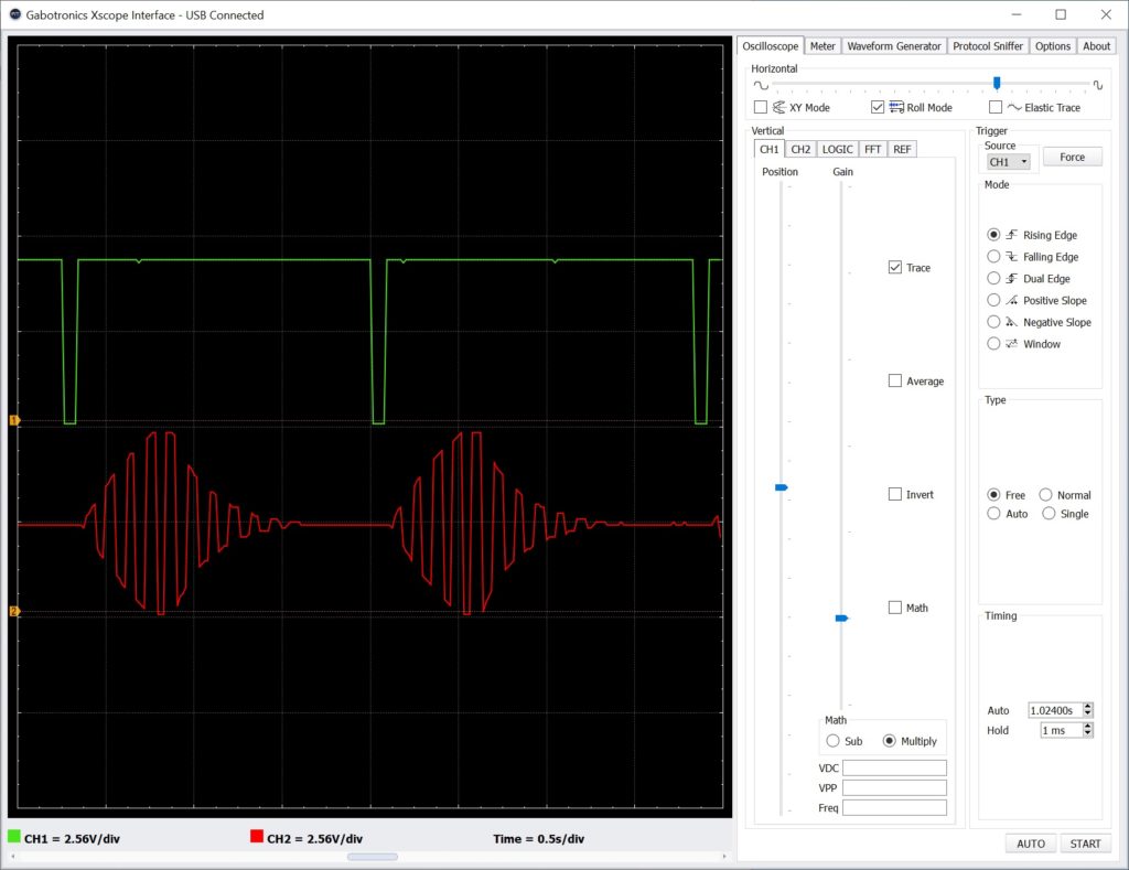
Yes, this actual works as shown in the oscilloscope traces below. The top trace is the gated CV signal from the MIDI Module. The bottom trace is the output of the Envelope Module which is connected to the Filter cutoff modulation input.

Modulating the filter with envelope shaped audio

littleBits envelope generator

I’ll bet that you’re wondering if the littleBits Envelope Module can be made into a conventional envelope generator. So did I. It would be great to have a conventional synthesis chain with separate envelopes for amplitude and filter with separate attack/release (AR) controls for each envelope.

Here’s one experimental solution:

               --> MIDI IN  --> Oscillator --> Filter --> Speaker 
| | ^
Power --> | | Trigger |
| V |
--> Envelope ----------------------

If you have a second Envelope Module, you can insert it between the Filter and Speaker Modules, forming a conventional OSC→VCF→VCA chain. I have only one Envelope Module and built the circuit shown above. I used a littleBits Split Module to send the Power output to the MIDI Module and Envelope Module. This is the ideal situation for powerSnaps, if you got ’em.

littleBits Power Module (old model)

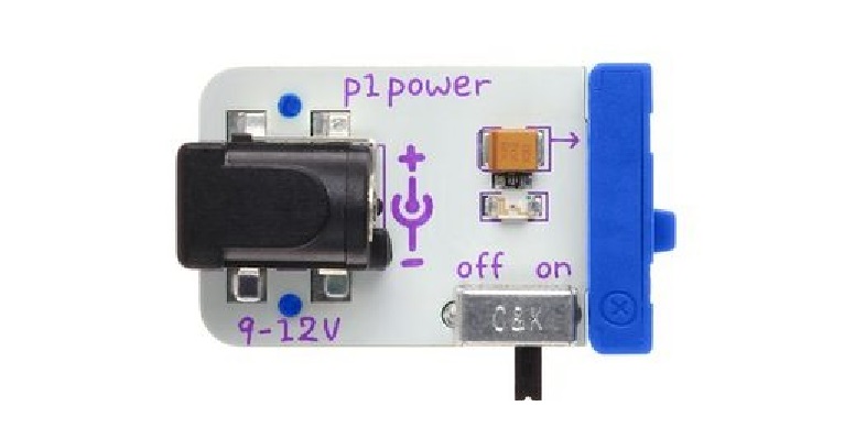
How does this circuit work? The Power Module provides the +5V and ground power rails, of course. The Power signal output is tied to 5V. Thus, the Envelope Module sees a constant 5V signal at its primary input. The littleBits MIDI Module triggers the Envelope module. The envelope generator inside the Envelope Module triggers and shapes the constant +5V input signal into the familiar attack and release envelope contour.

Output from the “pure” envelope generator circuit

The oscilloscope traces above show the gated CV signal (top/green trace) and the output from the Envelope Module (bottom/red trace). Yep, the final audio sounds exactly as expected having the familiar wah-wah filter funk. The final audio sounds cleaner when the filter cut-off frequency is modulated by the “pure” envelope generator.

One final detail. The internal littleBits envelope generator is based on a 555 timer circuit. If you’re curious about the internal design of this or any of the littleBits modules, be sure to visit the littleBits Eagle file repository where you will find schematics.

Copyright © 2020 Paul J. Drongowski

littleBits Control Signals

I got the itch to experiment with analog audio processing and finally unpacked the old littleBits synth modules. Folks hack the Korg Monotron series, so why not hack littleBits modules instead? The modules are inexpensive when compared with Monotron and are easily reconfigurable while experimenting.

Since I last wrote about littleBits (circa 2017), Sphero purchased the littleBits company in 2019. Fortunately, they retained the littleBits forum.

Not so good, neither Sphero nor littleBits provide precise documentation about synth module functionality or the input and output signal characteristics. Precise information is needed especially when interfacing modules with the outside world including module synth gear. Timing information, in particular, is needed.

We do know a few things about littleBits, however. littleBits modules normalize input and output signals to a 0 to 5 Volt range. Both digital and analog signals are normalized. Normalization facilitates the plug-and-play module architecture and you can freely interchange analog for digital and vice verse.

Background

Before diving in, here is a little background information about the signal types and terminology commonly used in modular synthesis.

Control voltage (CV)” is an analog signal which controls continuous functions like oscillator pitch generation, envelope and filter modulation, etc. CV sweeps continuously across an operational range, e.g., 0 to 5 Volts.

Gate” is a digital signal. It is an ON/OFF signal. A keyboard, for example, asserts gate when a key is pressed and drops gate when the key is released. Gate indicates a condition, e.g., a key is pressed. The leading and trailing edge of the gate indicates a change in the condition.

Trigger” is a digital signal similar to gate. However, trigger is usually a short digital pulse. Trigger is intended to indicate an event, like a clock tick, not just the presence or absence of a condition. Trigger signals often control synchronization.

Of course, electrons are electrons and one is free to combine CV, gate and tigger in any manner. Not all mixtures are meaningful (useful), however.

Details about CV, gate and trigger vary from manufacturer to manufacturer. Moog, for example, use the linear Volts per octave convention. On the other hand, old Yamaha and Korg synths use the Hertz per Volt convention. Maximum and minimum voltages level may differ by manufacturer and so on.

My goal here is understanding the convention used by littleBits.

littleBits MIDI and oscillator modules

I decided to start from the front of the synthesis signal chain and work back. The first stage in the synthesis chain is the littleBits MIDI module. A close look at the MIDI module signals in action should tell us how littleBits implement basic synthesizer control (CV, gate and trigger).

littleBits MIDI module

The MIDI module has a USB-B device port that presents itself to the USB-A host as a class-compliant MIDI device. The MIDI module supports both USB MIDI IN and USB MIDI OUT. However, the module operates in one mode (IN or OUT) at a time. The mode is selected by its mode switch (duh!).

  • IN mode: Receives MIDI messages from the host.
  • OUT mode: Sends MIDI messages to the host.

This blog post focuses on IN mode.

IN mode converts incoming MIDI note messages to two signals:

  • Gated control voltage (gated CV)
  • Trigger

Although littleBits call the digital output “Trigger,” it really is a gate signal, as we shall see.

littleBits Oscillator module

The littleBits Oscillator module is a pretty simple affair. The sole input is the (gated) control voltage which changes the pitch. The sole output is either square or saw wave as selected by the waveform switch.

The test rig

Here’s my test and measurement approach.

The littleBits signal chain consists of a power module connected to the MIDI module which drives a littleBits oscillator module. I split the gated CV signal sending it to both the oscillator and a proto module. The oscillator output is sent to a speaker module, giving me aural feedback. Hey, is this thing on?

MIDI module/Oscillator test circuit

The GND and gated CV signal are sent from the proto module to a Gabotronics Xminilab oscilloscope. I attached another proto module to the MIDI module “trigger out.” The GND and “trigger out” from that proto module are went to the second channel of the oscilloscope. Thus, I can monitor both the gated CV and “trigger out” and see the timing relationships between the signals.

SONAR/Oscilloscope test rig

The Xminilab front panel user interface is a little fiddly. So, I connected the oscilloscope to a PC running the Gabotronix oscilloscope application. This arrangement makes it sooooo much easier to configure the oscilloscope and to capture screen shots.

The USB MIDI comes from the PC, too. SONAR generates MIDI messages and sends them to the littleBits MIDI module. Test messages are produced from a repeating one measure loop (80 BPM or so). The repeating loop gives me good repeatability.

The signals under test

As noted by other experimenters, littleBits combine gate with CV functionality. When the MIDI module receives a note ON message, it:

  • Asserts the trigger signal, and
  • Drives the gated CV output with a positive voltage proportional to the MIDI note number.

The MIDI note range is C2 to C6 (4 octaves). MIDI note C2 generates a gate CV voltage of 0.2 Volts. From there, the output voltage increases by 1 Volt per octave (1V/oct). Each semi-tone step increases the voltage by 1/12 Volts. The module asserts trigger by raising its output voltage to 5V.

When the MIDI module receives the corresponding note OFF message, it:

  • Drops the trigger signal to 0V, and
  • Drops the gated CV output to 0V.

Notice that the gated CV output is asserted and dropped in parallel with the trigger output. Trigger is always driven to 5V while the gated CV voltage is positive and is proportional to the MIDI note number.

The screenshot below illustrates the operation of these two signals. The top trace (green) is the gate CV voltage. The bottom trace (red) is the trigger voltage. [Click images to enlarge.]

Gated CV (green/top trace) and “trigger” (red/bottom trace)

The MIDI test loop plays C2, C3, C4 and C5 in succession and repeats. The stair steps in the top trace show the effect of each successive note in the loop. The vertical display scale is 2.56V per grid division. You can see that each successive step is 1 Volt higher starting with C2 at 0.2V.

The trigger and gated CV traces are in temporal lock-stop, i.e., they rise and fall together. The width of the trigger signal is always the same width as the gated CV signal. Please recall that “trigger” in synth-speak is normally a fixed-width narrow pulse. That’s why I think the littleBits “trigger” signal is really a gate signal.

So, why do littleBits use a gated CV? Short answer: In conventional use cases, both gate and CV can be sent through a single wire (connection). The synthesist doesn’t have to route two separate wires (connections). The simplified wiring makes life easier for novice users (kids). The synthesist merely lines up a keyboard (sequencer, MIDI module) with an oscillator module and “it just works.” We will see other instances of the “It just works” philosophy in the envelope module, too.

C2, C3, etc. are MIDI note numbers and nice names. However, you’ll need to tune the Oscillator module to obtain the correct musical pitch.

Copyright © 2020 Paul J. Drongowski

COVID-19: Washington State July 12

The graphs below summarize the Washington State COVID-19 positivity rate through July 12, 2020. Data are taken from the Washington State Department of Health (DOH) and the University of Washington Virology Lab (UW). The DOH data are complete through July 4, 2020 and that is what is shown here. [Click images to enlarge.] I don’t report partial results.

Washington State Positivity Rate (DOH, July 4, 2020)
Washington State Positivity Rate (UW, July 12, 2020)

The UW data indicate an uptick in the positivity rate during the last week. This is consistent with my daily DOH tracker. Many states in the nation are experiencing a sharp increase and a few are heading into the weeds as indicated by their high positivity rates (15% and up). I dearly hope that we can reverse the most recent trend and suppress transmission.

I need to remind everyone that the positivity rate is a proxy for the true rates of COVID-19 incidence and prevalence.

We all need to renew our efforts — P.J. Drongowski

Best things in life are free

Yep, still here and no trouble staying busy! We’ve been hit by a tsunami of free on-line content and software sales. The good news — it’s free (or at a discount). The bad news — the amount of time required to download, install, activate and maybe, gasp, actually use some of these samples, plug-ins, etc.

The list of free stuff is astounding. The Loopmasters, Loopcloud, Plug-ins Boutique and Producer Tech conglomerate has been veru generous during the pandemic and the summer season. The first stay-in and create promotion distributed:

That’s a bunch of good stuff, especially Neutron Elements. I haven’t dipped into Producer Tech, as yet, but the Ableton Live tutorials are inviting.

I just cashed in the summer stay inspired promotion:

These plug-ins are really worth it and useful. I Heart NY does parallel compression, good for mastering among other uses. Vocal Splitter separates mono vocals into stereo (ye olde split, delay and detune trick). Smasher is an Urei 1176 compressor emulation dedicated to the British all-buttons-in sound. Sure, the plugs are somewhat single purpose, but they sound great and are simple to use. Frankly, with all of this free content (!), I don’t have time to dial things in. 🙂

Other notable free plug-ins are:

Sweetwater ran a promotion with iZotope, giving away the Ozone Elements mastering suite. Between Ozone Elements and Neutron Elements, that’s half of the iZotope Elements suite for nada.

I need to mention my favorite score from the Christmas holiday season: Arturia’s EMT-140 Plate Reverb. I have a fondness for plate and Arturia put together a beautiful EMT-140 emulation.

If that’s not enough, shake in the Korg software sale including Korg Module Pro and discount Cubase updates from Steinberg.

Plugin Boutique had a sale on zplane deCoda. deCoda is like Yamaha’s Chord Tracker on steroids, building on zplane’s experience in spectral analysis. Sure, it’ll identify the measure, sections and chords. However, you can draw MIDI notes on top of a spectral plot and export the MIDI to a file. A great way to capture a melody line from a song. deCoda has a focus panel which restricts analysis and playback to a specific frequency band and area within the stereo field. I see many uses beyond chord extraction!

Check out this introductory deCoda video. zplane have a v1.1 update in beta testing now. The beta adds the ability to save the chord progression to a file — a must-have feature. In v1.0, you need to jot the chords down by hand.

Hey, hey. If you keep your eyes and ears open, you can save some serious cash. The plugs and stuff mentioned here are first-rate, not sleazy hacks. Nows all we need is a time machine to learn, experiment, and put everything to good use.

Copyright © 2020 Paul J. Drongowski