Although I’m posting about music technology again, I still track the local COVID-19 situation. This disease, unfortunately, is still out there with months to go until a safe, tested vaccine.
The Washington State Department of Health web site is changing the way it counts and reports negative tests. The DOH site has left us blind about testing for over one week; they promise to have negative test results beginning August 24. I will do a major revision of my own when the new data are available.
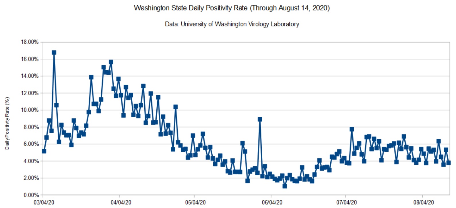
In the meantime, here is a graph of the daily positivity rate for Washington State using data from the University of Washington (UW) Virology Lab. UW does not break down test results by county, age, etc. It’s strictly specimens in, results out.
Washington State COVID-19 daily positivity rate (UW, August 14, 2020)
The State as a whole did quite well — for a while. The positivity rate for King County, the most populous county, is around 3 percent. Not bad. UW performs tests for the entire state and reflects problem areas elsewhere, notably Yakima and a few other agricultural areas. Snohomish county, where we live, is running at 5 to 7 percent — nothing to brag about and misses the state target (2 percent).
This situation demonstrates how one populous county can make a state appear better or worse overall. People outside of King County should check their local statistics and not feel comfortable thinking that COVID-19 is in check. Don’t ride on someone else’s coat tails!
My last blog post took a look at the Pitch and Gate control voltages (CV) generated by the Arturia Keystep. Keystep’s Pitch and Gate behave conventionally. I also took note of how they differ from the littleBits gate CV signal, which combines pitch and gate control into a single signal. I mentioned two potential approaches for interfacing Keystep to littleBits:
Driving littleBits with Keystep’s Pitch and Gate, and
Sending MIDI to a littleBits MIDI module that handles conversion to littleBits gated CV.
I tried each approach. Here’s what I learned.
Keystep Pitch and Gate circuit
In this approach, the littleBits Oscillator is always running, always generating an audio signal. The Oscillator tracks the Gate voltage generated by the Keystep. The trick is opening up and shutting off the audio signal. For that, I put a littleBite Envelope module after the Oscillator and triggered the Envelope with the Keystep Gate voltage.
The resulting circuit is:
            Keystep Pitch                Keystep Gate
                  |                           |
                  V                           V
    Power --> CV Module --> Oscillator --> Envelope --> Speaker
The Keystep Pitch output is connected to the “CV IN” connector on the CV Module. The CV Module routes the incoming control voltage to its output, which sends the pitch control voltage to the Oscillator Module. The Keystep Gate output is connected to the Envelop’s Trigger input.
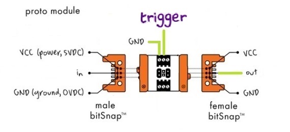
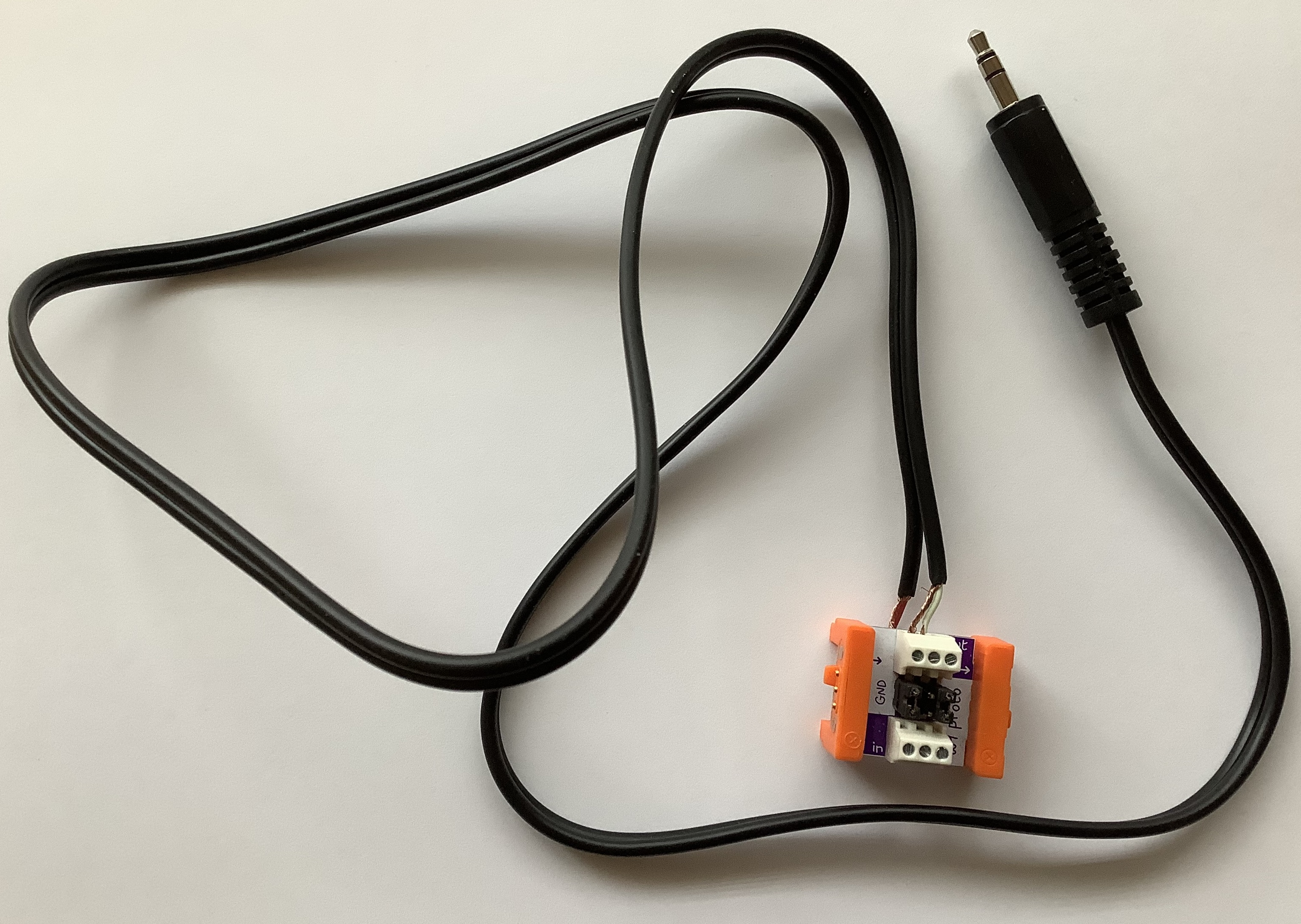
littleBits Proto Module ins and outslittleBits Proto Module and quick-and-dirty patch cable
The Pitch output to CV IN connection is a standard 3.5mm patch cable. But, how is the 3.5mm Gate jack connected to the Trigger bitSnap? The littleBits Proto Module provides the solution. I cut a (stereo) patch cable in two and connected the shield and tip wires to the littleBits Proto Module as shown above. The Proto Module sends the incoming trigger signal (the Keystep Gate) to the output bitSnap. From the output bitSnap, the trigger signal goes to the Envelope Trigger input.
Properly, I should have used a mono patch cable, but I didn’t have one to sacrifice. I connected the TIP and SHIELD wires, leaving the RING unconnected.
That’s the entire setup! For testing purposes, I attached oscilloscope probes to the trigger (Keystep Gate) and the Envelope’s audio output. I also verified correct operation at intermediate points along the main signal path.
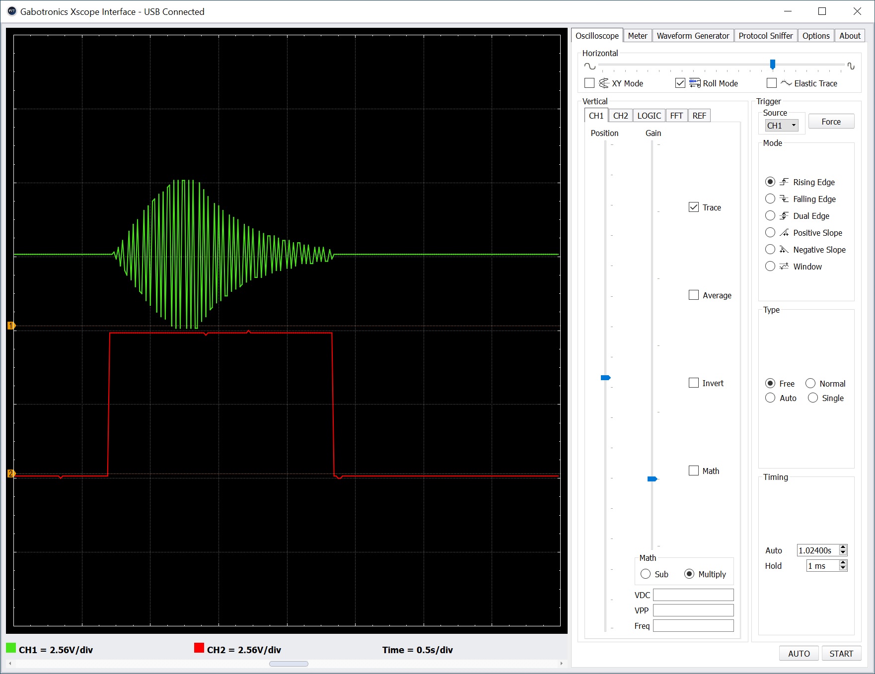
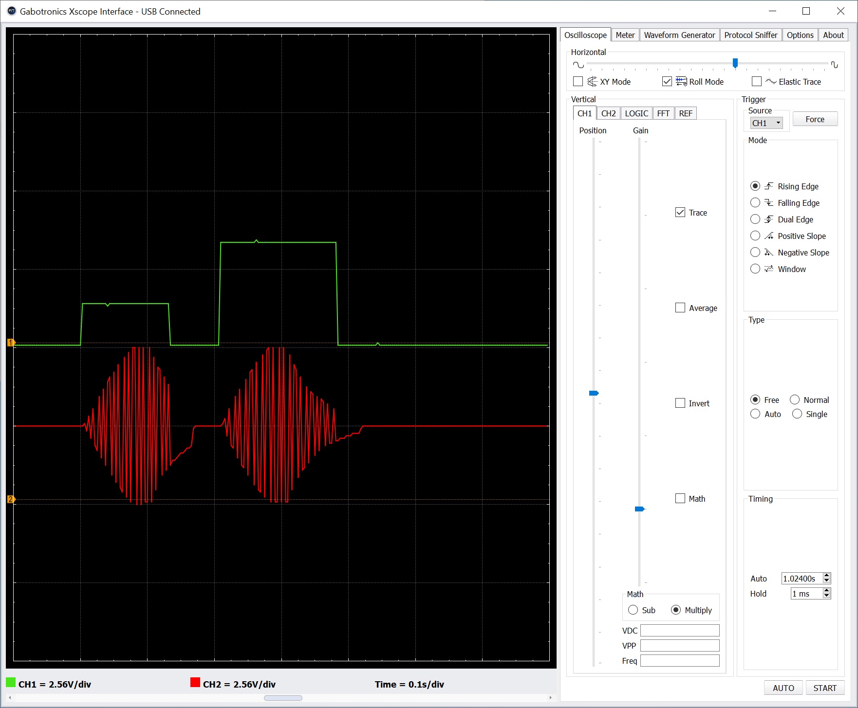
Oscillator audio (top) and Keystep Gate (bottom)
The screenshot above shows two oscilloscope traces. The top trace (green) is the final audio signal. Note the attack-release envelope around the oscillator signal. The bottom trace (red) is the trigger (Keystep Gate) signal. If the trigger is dropped before the entire envelop completes, the audio cuts off (i.e., it’s truncated). If the trigger is held beyond the combined attack plus release time, the audio signal merely stays at zero. The audio signal remains shut off until another trigger (the rising edge of Gate) is received.
Although this circuit gives us the desired behavior, it wasn’t easy getting things to work reliably. I seemed to suffer more than the usual loose connections and other lab-bench gremlins.
           Keystep MIDI OUT
                   |
                   V
    Power --> MIDI Module --> Oscillator --> Envelope --> Speaker
MIDI arrives on the MIDI Module’s 3.5mm connector instead of the USB port. Otherwise, the main signal flow is the same.
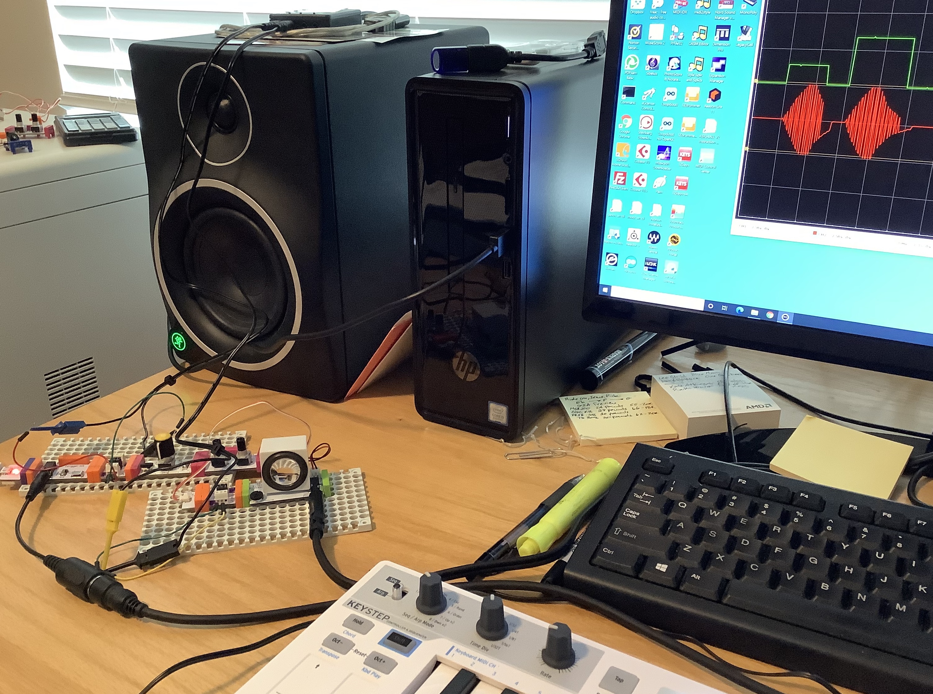
Keystep/littleBits test rig
I monitored the gated CV signal produced by the MIDI Module and the audio signal generated by the littleBits Envelope using the oscilloscope. I played two notes in quick succession. The second note is two octaves higher than the first note.
littleBits audio triggered by MIDI Module
In the screenshot above, the top oscilloscope trace is the gated CV signal. The bottom trace is the synthesized audio. Not any different than the Pitch and Gate control volltage approach, eh?
Since the final audio is much the same, I would go with the MIDI Module circuit. It is simpler and its wiring is less touchy. The circuit uses the littleBots modules pretty much as intended by the littleBits engineers.
The MIDI Module approach makes the Keystep Pitch, Gate and MOD outputs available for other duties such as key-scaling (i.e., varying the effect of a sound modifier by keyboard pitch), modulation and user control. Don’t forget to insert littleBits Dimmer Modules (potentiometers) along control paths in order to set modulation level and so forth.
Today’s post continues with Arturia Keystep. Although the Keystep Gate and Pitch control voltage (CV) signals are conventional, I wanted to visualize them with an oscilloscope. I strongly recommend getting an oscilloscope when working in modular synthesis because pictures/graphs help understanding. [We haven’t even gotten to the audio yet!] I connected the Gabotronics Xminilab oscilloscope to the Keystep’s Gate and Pitch CV outputs and took a quick look.
First thing I noticed was a 12V positive trigger level. Holy smokes, I hope I didn’t apply that high signal to littleBits way back when! littleBits modules operate in the 0V to 5V range. Fortunately, littleBits input ports have an ON Semiconductor ESD9L5.0ST5G ESD suppressor/TVS diode, which protect against ESD and transient voltage events. Still, it’s better to configure voltages correctly ahead of time and not risk an accident.
Second thing is that Keystep CV voltages cannot be configured through its front panel. That’s somewhat understandable in a low cost product like Keystep. Control voltages are configured by Arturia’s MIDI Control Center (MCC) software — a free download for Keystep owners.
Here is the control voltage configuration that I used during testing:
MIDI CV output: Volt per octave
0V MIDI note: C1
Note priority: Last
MOD CV source: Mod wheel
MOD CV max voltage: 5V
Pitch bend range: 2 semitones
Gate CV output: V-trig 5V
Keystep supports V-trigger 12V and S-trigger in addition to V-trig 5V. S-trigger is the old Moog convention that is not used very much anymore. It’s sometime called “negative trigger,” but it’s really a strange creature requiring a special connector.
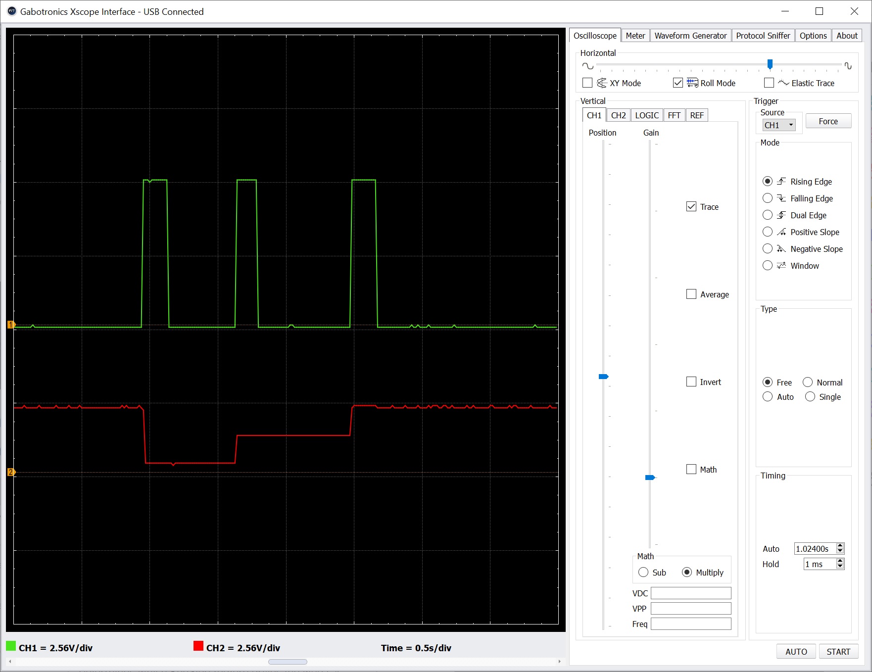
Keystep Gate (green) and Pitch (red) control voltages
The screenshot above shows the Keystep in action. [Click image to enlarge.] The top trace (green) is the Gate (V-trigger 5V) output and the bottom trace (red) is the Pitch output. The Gate signal is, er, a gate. It goes high when a key is pressed, stays high while the key is held, and goes low when the key is released.
In the example, I played three notes where each note is an octave apart. The vertical oscilloscope scale is 2.56V per grid division. Each step up in the bottom trace (Pitch) is about 1V. Also, you see the Gate signal hit a maximum 5V.
In the future, I may need to tweak Keystep’s 0V MIDI note parameter if I drive the littleBits Oscillator module with the Pitch signal. One needs to find a happy operational sweet spot between Keystep octave transpose and note range versus the limited 5 octave range of the Oscillator module. Keystep’s Pitch signal ranges from 0V to 10V, and I don’t want to drive the littleBits Oscillator with more than 5V, if possible. MCC does not allow us to specify a maximum, do-not-exceed Pitch voltage.
One way around the pitch voltage issue is to control the littleBits Oscillator via the littleBits MIDI Module instead. In that case, the Keystep 5-pin MIDI OUT connects to the MIDI Module (mode switch set to IN) over a Korg convention, 5-pin to 3.5mm adapter. (The O-Coast adapter adheres to the same convention and works, too.) With the MIDI approach, we don’t need to worry about over-driving the Oscillator module with a high, out-of-range voltage. The littleBits MIDI module tops out at 5V.
I have both the littleBits MIDI module and littleBits CV module. Thus, I can drive littleBits oscillators via MIDI and send the Keystep MOD CV to the littleBits CV module for modulation duties. With the Keystep MOD CV max voltage set to 5V, I should be safe. If I need to reduce the MOD CV range further, I can always run the output from the littleBits CV module into a littleBits dimmer (potentiometer) and attenuate the level.
The MIDI module approach also produces the gated CV signal expected by littleBits oscillators. The Keystep Pitch output provides a simple, steady voltage level and doesn’t have an in-built gating function. When you hit a key, the Keystep changes the Pitch output voltage accordingly and the Keystep holds that voltage even when the key is released. If connected to a littleBits Oscillator, the Oscillator will never see a release event, that is, the Pitch voltage never drops to 0V when a the key is released. The littleBits Oscillator merrily continues to play! On the other hand in littleBits-world, the gated CV drops to zero. Thus, littleBits combines pitch control and trigger (gate) into a single signal.
One could build a simple converter from separate gate and pitch CV to the littleBits gated CV. I’m thinking of a voltage-controlled SPDT analog switch like the Texas Instruments TS5A9411 (or MAXIM MAX4544, etc.). The trigger (gate) signal controls the switch. When the trigger is low, the signal connects to ground and passes 0V. When the trigger is high, the switch passes the Pitch CV signal.
Another possible work-around is to follow the littleBits Oscillator with an Envelope module and connect the Envelope’s trigger to the Keystep Gate output through a littleBits CV module. [Whew!] The Envelope should pass and shut off the Oscillator’s sound when the gate is asserted and dropped, respectively. I’m going to give this idea a go.
As part of the littleBits revival, I pulled the Arturia Keystep from storage. The Keystep has a nice keybed and sequencer, and supports a wide range of interface options: 5-pin MIDI, CV, gate, sync and USB MIDI.
Although I love its industrial design, the Keystep keys have always been somewhat unreliable. Straight out of the box, one of the keys did not trigger reliably. After moving and storage, unfortunately, several more keys became flaky or non-operational. Time to tear down and clean! [Click images to enlarge.]
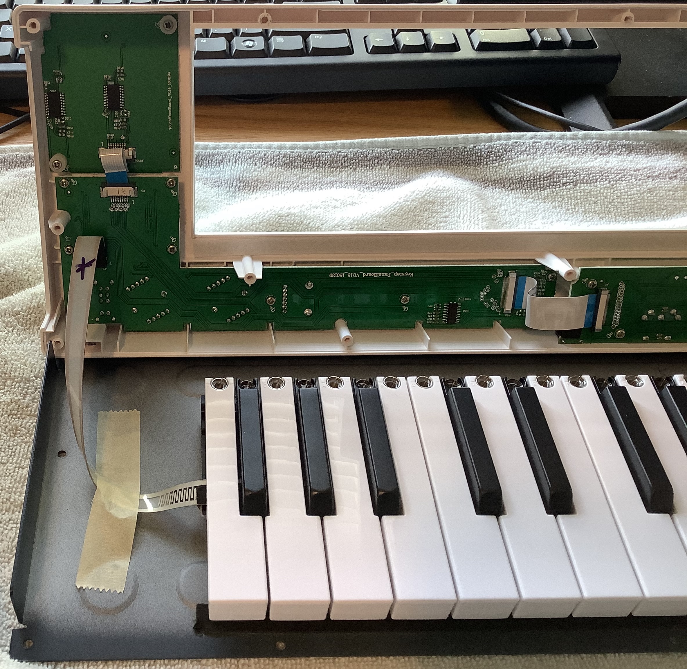
Arturia Keystep wide open
I watched a Youtube video covering repair of the aftertouch ribbon. Initial disassembly is straightforward: 1. Pull off the knobs. 2. Remove the 14 large screws on the bottom. 3. Carefully open the top (white or black front panel.
Arturia Keystep aftertouch cable (connected)
The key assembly connects to the main electronics through two ribbon cables: the aftertouch cable and the key matrix cable. I marked the top side of each cable so I would know the correct cable orientation during re-assembly.
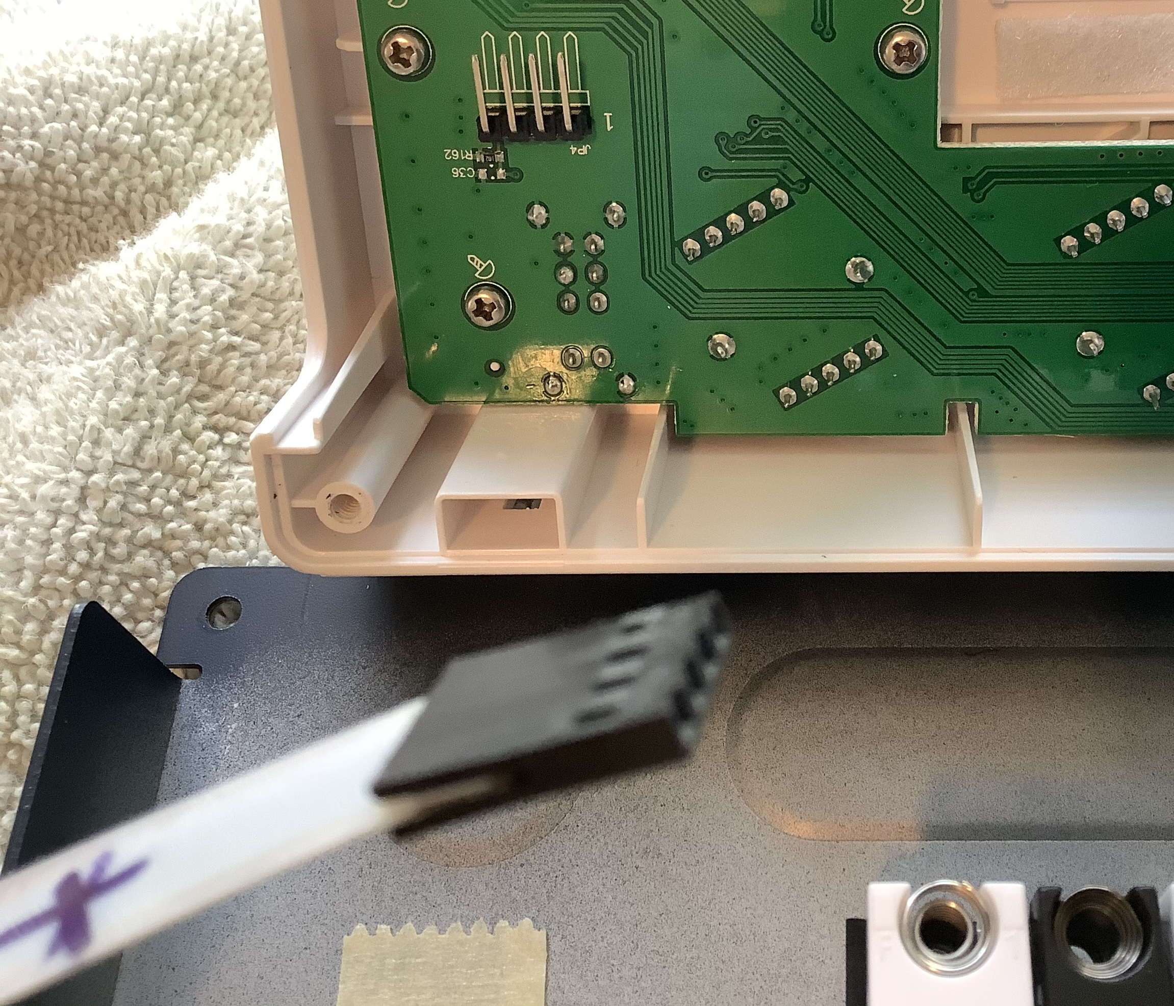
Keystep aftertouch cable (disconnected)
The aftertouch cable has a four socket connector that slides over four right angle pins on the printed circuit board. Disconnecting it is easy; just slide the connector out in the same direction as the pins. Please note the black X. That’s my mark so I know how to orient the cable when putting everything back together. This is important because there isn’t an indexing mechanism for the cable and it’s possible to insert it the wrong way.
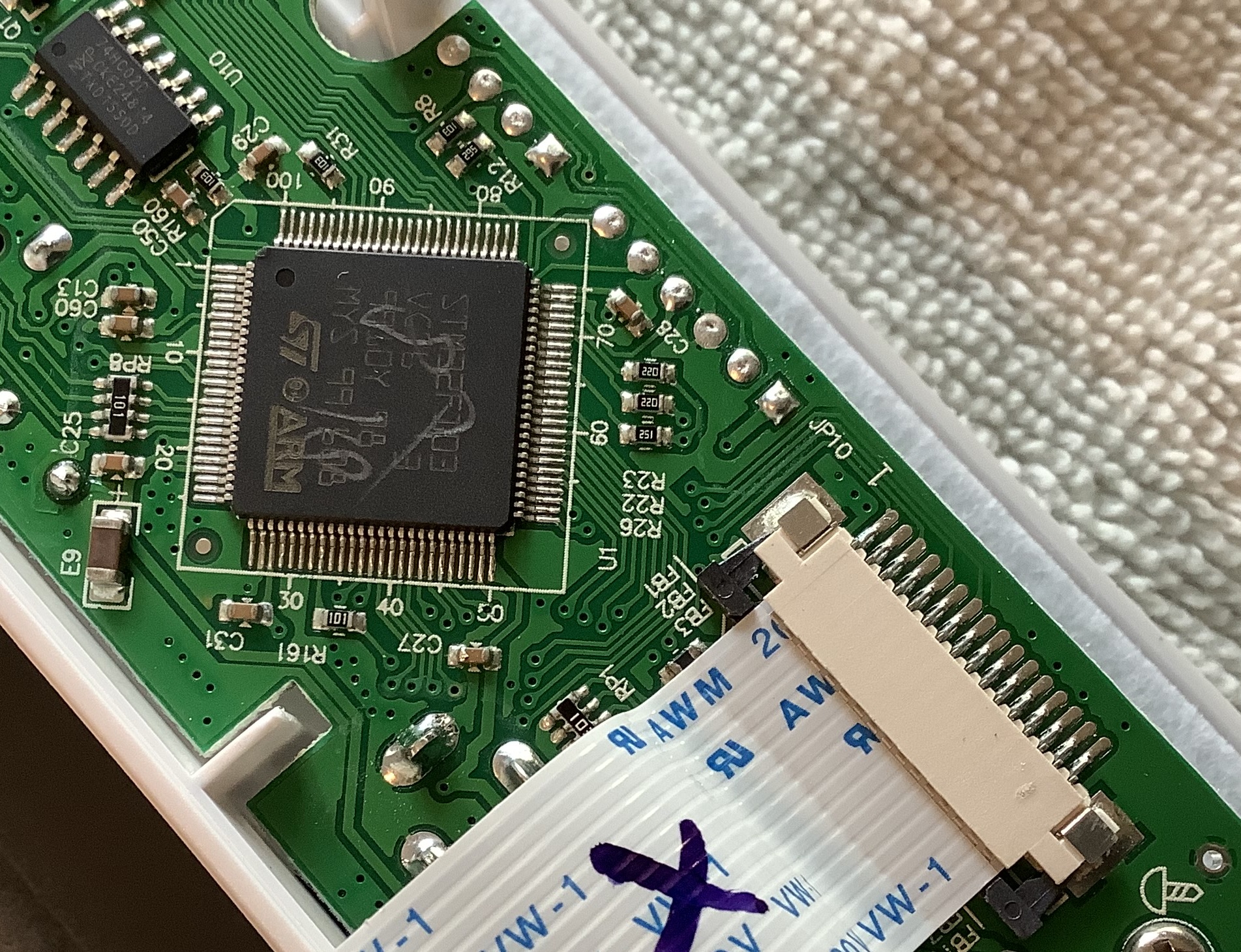
Next, one needs to disconnect the key matrix cable. Once again, I marked the cable in order to know its correct orientation. The cable is paper thin with exposed leads at the end. I always get faked out by these newfangled PCB cable connectors. Slide the two black tabs on either side of the connector in order to release the cable. During re-assembly, you’ll insert the cable and slide the tabs to lock the cable into place.
While we’re here, that’s an ST Micro STM32F103 ARM processor which is the brains of the whole operation. Ya know, for a 100 bucks (USD), there’s a lot of technology and quality built into this thing!
After disconnecting the cables, the front panel electronics can be separated from the keybed in the metal chassis tray. Now it’s time to remove the keybed itself by removing the 10 small screws on the bottom of the tray.
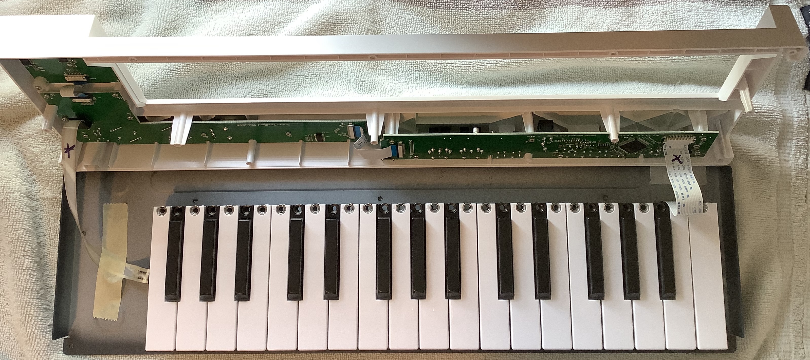
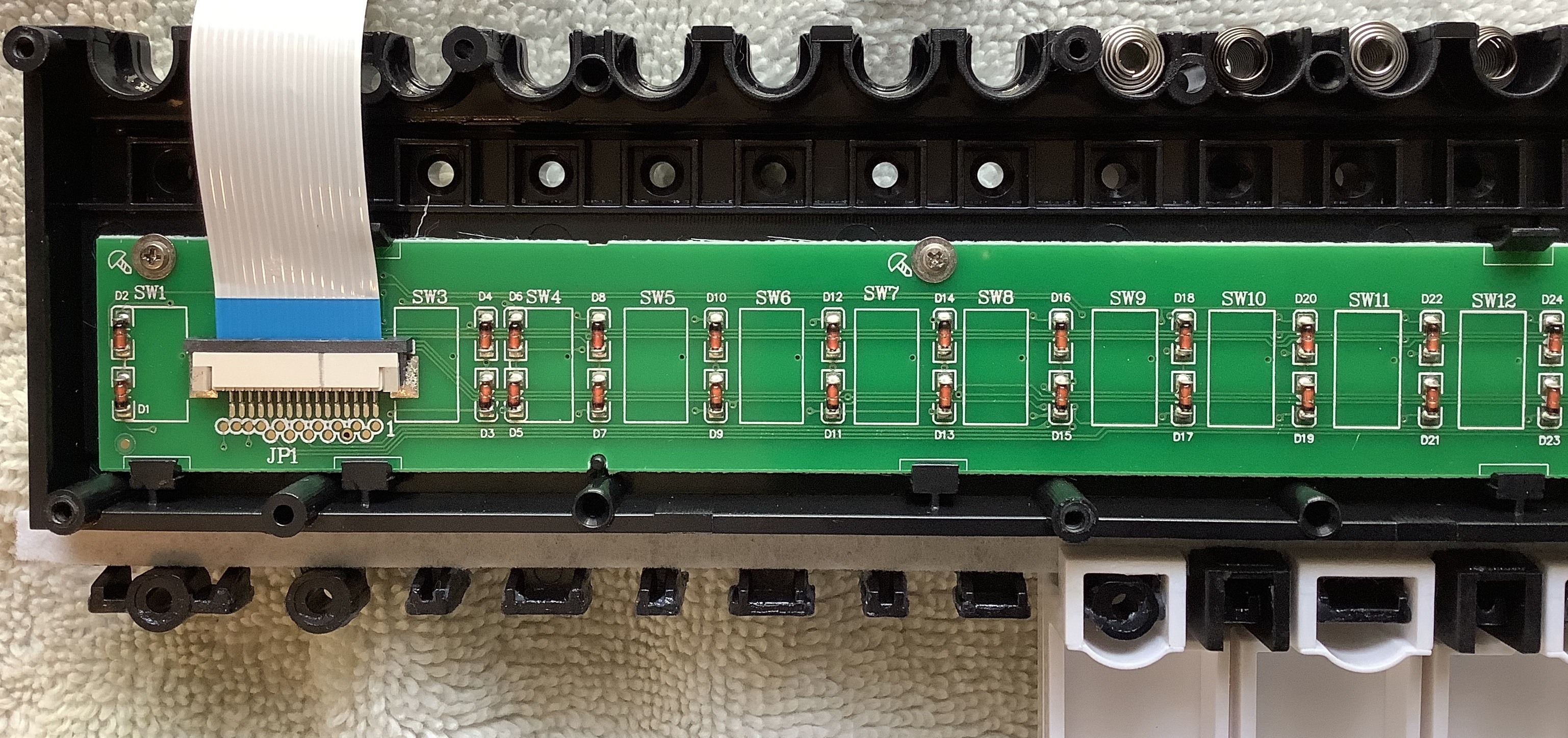
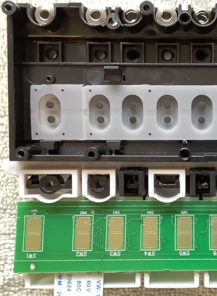
Keystep key switch matrix PCB (ignore the missing keys)
Flip the keybed over and you see the key matrix PCB. The key matrix lets the ARM scan the key contacts. The tiny components are switching diodes. For the time being, ignore the missing keys (!). I’ll explain later…
Next, remove the four tiny screws holding the key matrix PCB in place. Then, carefully push back the four black plastic tabs, one at a time. Remove the PCB and flip it over.
Now you see the actual key contacts. This is the money shot. The PCB has two maze-like traces for each contact. The black dots on the rubber contact strip make two separate electrical connections on the PCB when a key is pressed. One connection is made first, followed by the second connection. The ARM software senses the connections and measures the time between contact. The software maps this time into the MIDI note velocity.
At this point, I used alcohol prep pads (70% isopropyl alcohol) to clean both the PCB traces and each of the black dots on the rubber contact strip. These are the same small pads that doctors or nurses use before a finger stick test. Be gentle! I didn’t see any visible dirt, so maybe key flakiness is due to manufacturing residue. [I’m not a smoker.] Based on Web comments, flaky Keystep keys is a common problem — a frequent problem in what is otherwise a fine product.
From here, you need to reverse the disassembly steps in order to nail everything back together again.
Fixing broken keys or aftertouch
Now, to explain the missing keys. The original video demonstrates a repair to the aftertouch strip. I naively thought that I could get access to the key contacts through the top of the keybed. You only need to remove keys when fixing the aftertouch strip or broken keys. Do not remove keys if your goal is only contact cleaning.
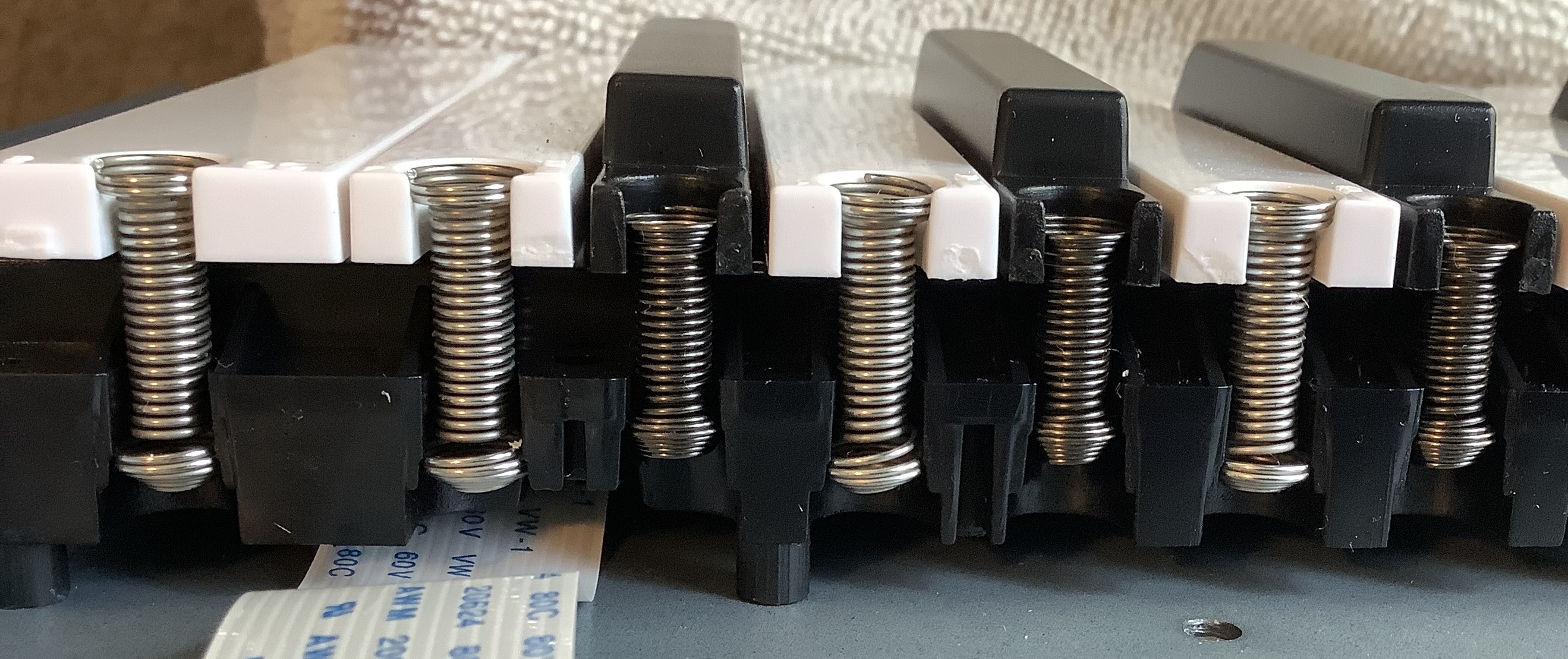
Keystep key spring detail
My mistake did create a photo-op, however. In the picture above, you see the springs which give the keys their bounce. The springs hold the keys in place. To remove a key, you need to gently push down on the spring and release the “rounded” end of the spring from the black keybed frame. These little buggers will fly off, so be careful! During re-assembly, the conical ends fit into the key holes. Stretch the spring until the rounded end fits into the corresponding pocket in the keybed frame. Another re-assembly tip: do all of the black keys first.
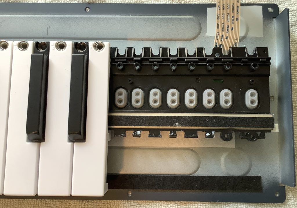
Keystep with keys removed
The final picture shows the top of each rubber contact pair poking up through the black keybed frame. These are the top sides of the rubber contacts that we cleaned. The black strip running along side the key contacts is the aftertouch strip.
I connected the reassembled Keystep to my PC (via USB) and got the familiar start-up light show. I launched MIDI OX and tested each key. All keys responded quickly and reliably.
All in all, the process was relatively easy although care must be taken. I like the Arturia Keystep and love it even more, now that all of the keys are working.