
Discussions about Yamaha Montage/MODX AWM2 and FM-X sent me digging into the past to unearth early AWM and FM implementations in order to get insight into today’s tone generation hardware. Although Yamaha do not publish design information about their proprietary SWP, SWX, SWL, etc. processors, they have published datasheets for their merchant line of LSI products. Yamaha were very active in the mid- to late-1990s when desktop music (Soundblaster, XG, Sondius, etc.) was king.
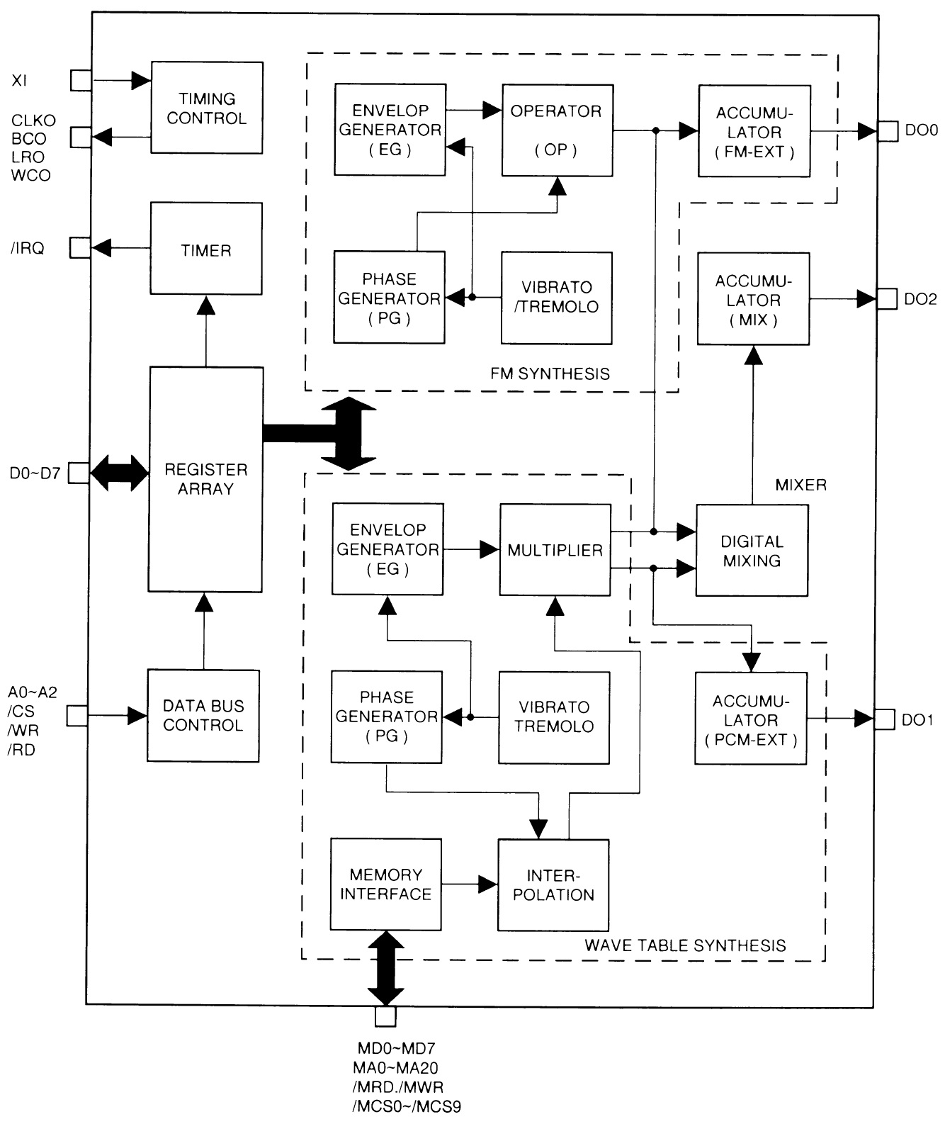
The Yamaha YMF278B OPL4 was one such LSI component. The OPL4 combines a 2-/4-op FM synthesizer and a wave table synthesizer on a single 80-pin quad flat pack (QFP). The FM synthesizer can:
- Generate 18 voices in 2-op modes or 15 2-op voices plus five rhythm sounds.
- Generate 6 voices in 4-op mode with an additional 6 voices in 2-op mode, or 6 voices in 4-op mode with an additional 3 voices in 2-op mode and five rhythm sounds.
The FM synthesizer has eight selectable waveforms and generates a stereo output. The wave table synthesizer can generate 24 voices simultaneously (i.e., 24 voice polyphony) producing stereo output at a 44.1kHz sampling rate with bit depths of 8-, 12- and 16-bits. Wave ROMs up to 32Mbits are supported with up to 512 wave tables.
The OPL4 has six sound channels which can be sent to an external DAC (YAC513) or a digital effects processor (YSS225). Sadly, documentation for the YSS225 cannot be found on-line. The YSS225 is said to perform reverberation, echo, flange and other effects.
The FM and wave table synthesizers are two separate hardware units. I wouldn’t be surprised if this is still the case in the modern day SWP70 Standard Wave Processor. Separation lets the engineers optimize the synthesis hardware for a particular synthesis type.
Wave table synthesis
The OPL4 does not implement AWM2 synthesis. The synthesizer does not have the AWM2 filter hardware. This is not too surprising because in that era, Yamaha regarded AWM2 and its analog-like filter as a special competitive advantage. Why would they give that same advantage to other sound card vendors? It’s a safe bet, however, that the XG-compliant variants are full AWM2.
Nonetheless, a peak inside gives us a look at Yamaha’s wave table machinery. The synthesizer consists of a synthesis core that fetches waveform samples and waveform meta-data from external wave memory.
Quoting the OPL4 data sheet:
The wave table synthesizer can generate up to 24 sounds simultaneously. Each sound is referred to as a “channel”. The channels are numbered from 1 to 24. These numbers are called “channel numbers”.
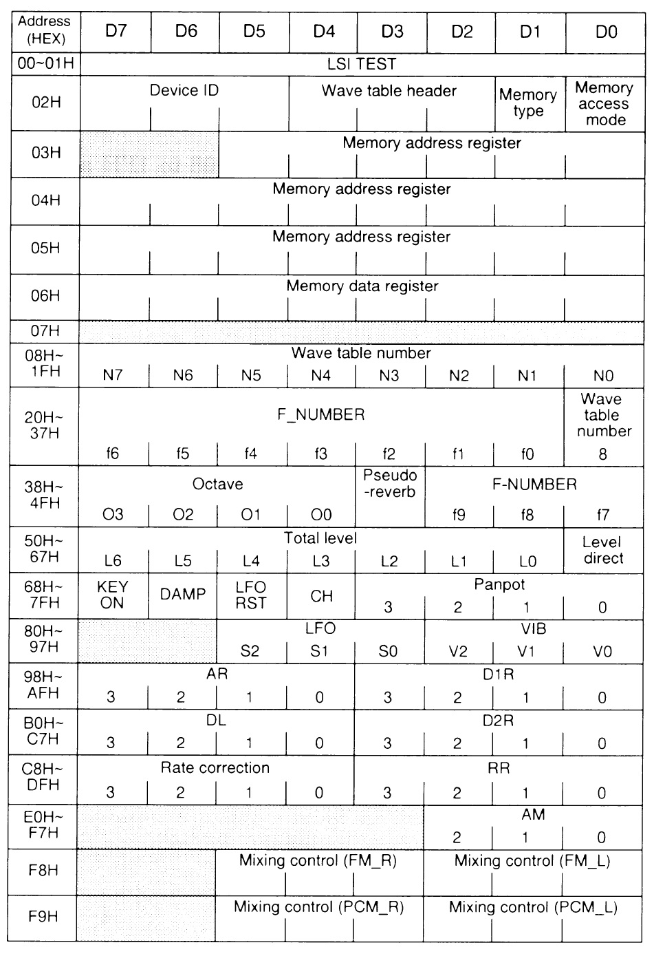
Wave table synthesis is controlled by a few hundred registers. The main control CPU writes common and channel-specific synthesis parameters into the registers. The synthesizer reads the registers during each synthesis macro-cycle and produces a new sound sample for each channel. The channel-specific control registers are organized into register groups. Each group consist of 24 registers, i.e., 24 values of a specific synthesis parameter type, one value per channel. A quick glance at the table below clarifies the register organization and the wave table synthesis parameters. Parameters for envelope generation, pan, LFO control, etc. are easily identifiable. (The YMF278B data sheet has the details).
I conjecture that today’s SWP70 is organized in a similar way. The CPU-SWP70 communication bus is a memory bus that gives the CPU direct access to the SWP70 synthesis control registers. Think about it. With 128 stereo AWM2 channels, there are several hundred (thousand!) synthesis values which must be configured at the hardware level. Software’s job is easier and fast by making the synthesis registers (channel-specific parameter value) directly accessible.
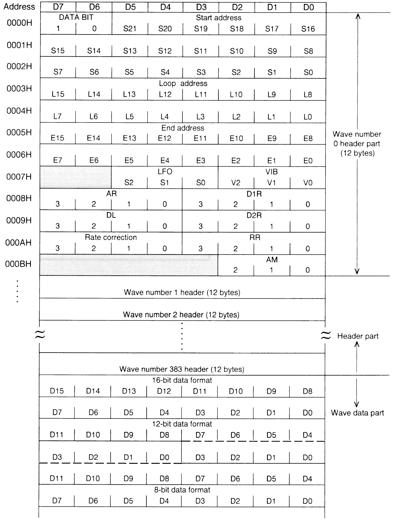
The waveform data and meta-information in external memory cosnsist of two parts: Up to 384 waveform headers and the waveform sample data. Each waveform header is 12 bytes containing:
- Wave data start address
- Loop address
- End address
- Voice parameters: LFO, VIB, ADSR, etc.
Today’s wave table is probably similar albeit much bigger. Explore Yamaha’s Universal Voice Format (UVF) and you’ll see what I mean.
FM synthesis
The OPL4 supports 2- and 4-op frequency modulation (FM) synthesis. Quoting the data sheet:
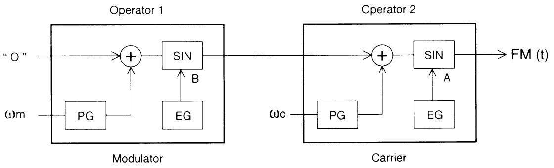
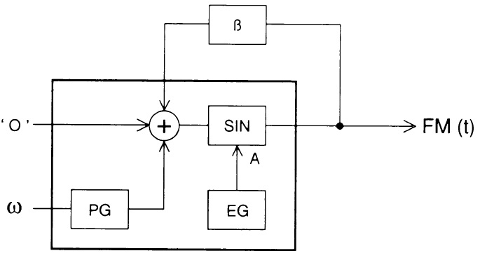
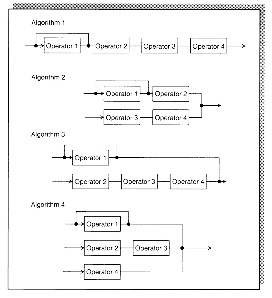
The part that generates one sine wave is called an “operator”. A combination of these operators is called an “algorithm”. The first stage operator (see diegram below) is called the “modulator” and the second stage operator is called the “carrier”. The frequency and envelope can be set for each operator. “Feedback FM” is available to generate a wider range of sounds.
Like the wave table synthesizer, the FM synthesizer has a large table of common and channel-specific synthesis parameters. The register table organization is a little more complicated. Quoting:
The OPL4 has 36 circuits that generate a sine wave. A circuit which generates a sine wave is called a “slot”. A sound unit which is generated by combining two or four operators is called a “channel”. There are two kinds of sound generation control registers: registers settable in slot units and registers set in channel units.
In 2-op mode, two slots are used to generate on FM sound. With 36 available slots, 18 channels of sound can be generated. In 4-op mode, four slots are used to generate one FM sound. Six channels are generated using 24 slots.
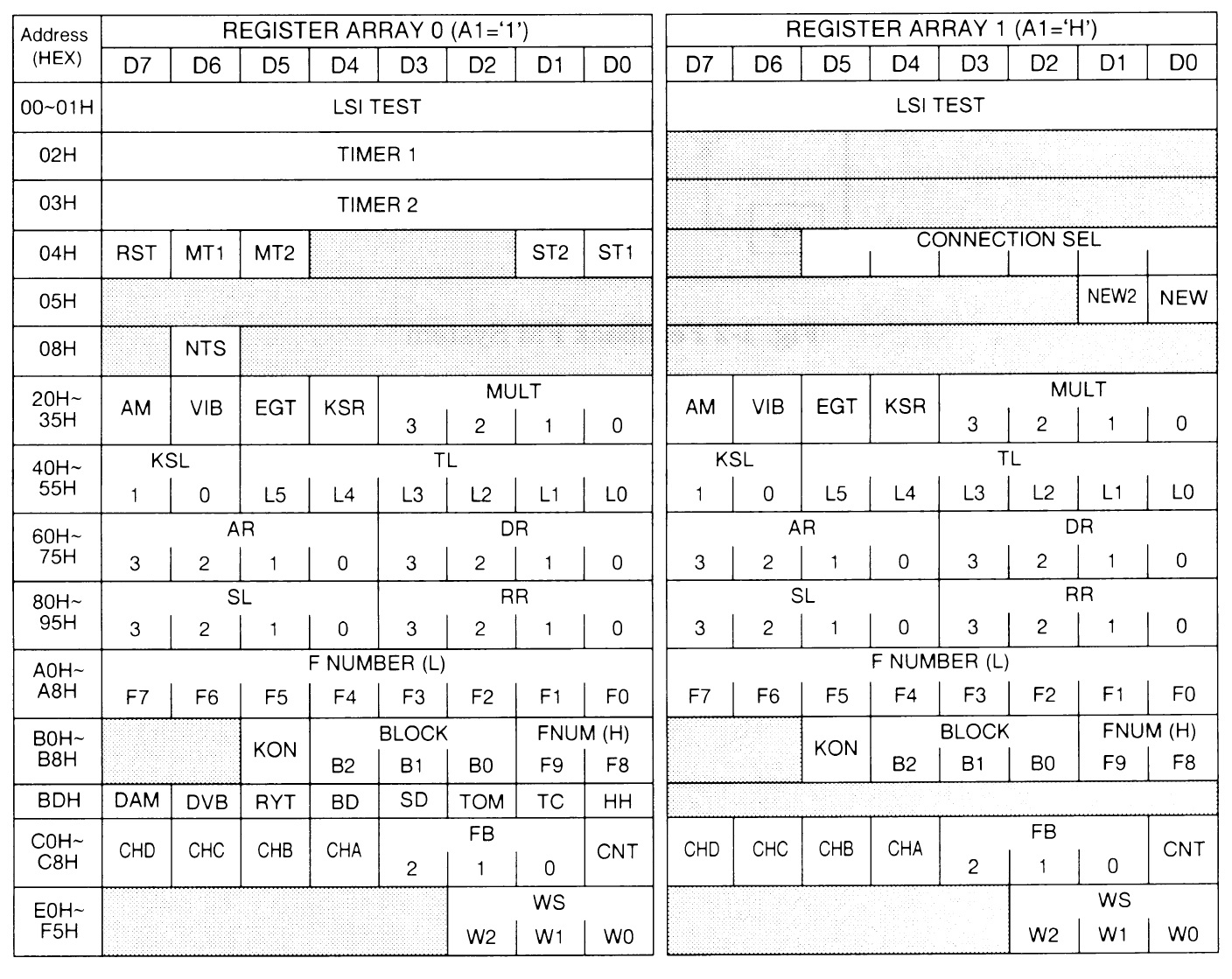
Whew! Given the two dimensional nature of register organization, addressing a specific parameter value for a specific operator is a complicated matter. (See the data sheet for details.) Without going a deep dive into register addressing, here is an image showing common and channel-specific synthesis parameters.
Summary
I would say that the overall architecture today (SWPxx) is not unlike the architecture of yesteryear. The number of synthesis parameters, of course, has exploded with new features in the wave table synthesis hardware (filtering!) and FM synthesis hardware. Modern FM can route FM output samples to AWM2 wave table filters, adding many wrinkles to datapath and control design.
The main CPU is responsible for channel allocation as notes are played and for channel deallocation as notes are released and completed. Once a channel is allocated, the main CPU must write the appropriate voice parameters into the channel registers. Then, it’s up to the synthesizer hardware to crank out a new sound sample at a 44.1kHz rate. Of course, the per-channel sound samples must be mixed and routed to the DSP effects processors. I would love to get a look at the mixing and DSP processing.
I hope this trip into the past gives you some insight into present-day AWM2 and FM-X hardware and an appreciation for the complexity and sheer number of details at the 10,000 foot level of digital synthesizer design.
Copyright © 2019 Paul J. Drongowski
Yamaha hold many patents on wave table and FM synthesis techniques. I recommend U.S. Patent 5,250,748 (1993) which describes the digital filter in AWM. For the modern era, I suggest U.S. Patents 8,779,267 (2014), 8,957,295 (2015) and 9,040,800 (2015).