I got the itch to experiment with analog audio processing and finally unpacked the old littleBits synth modules. Folks hack the Korg Monotron series, so why not hack littleBits modules instead? The modules are inexpensive when compared with Monotron and are easily reconfigurable while experimenting.
Since I last wrote about littleBits (circa 2017), Sphero purchased the littleBits company in 2019. Fortunately, they retained the littleBits forum.
Not so good, neither Sphero nor littleBits provide precise documentation about synth module functionality or the input and output signal characteristics. Precise information is needed especially when interfacing modules with the outside world including module synth gear. Timing information, in particular, is needed.
We do know a few things about littleBits, however. littleBits modules normalize input and output signals to a 0 to 5 Volt range. Both digital and analog signals are normalized. Normalization facilitates the plug-and-play module architecture and you can freely interchange analog for digital and vice verse.
Background
Before diving in, here is a little background information about the signal types and terminology commonly used in modular synthesis.
“Control voltage (CV)” is an analog signal which controls continuous functions like oscillator pitch generation, envelope and filter modulation, etc. CV sweeps continuously across an operational range, e.g., 0 to 5 Volts.
“Gate” is a digital signal. It is an ON/OFF signal. A keyboard, for example, asserts gate when a key is pressed and drops gate when the key is released. Gate indicates a condition, e.g., a key is pressed. The leading and trailing edge of the gate indicates a change in the condition.
“Trigger” is a digital signal similar to gate. However, trigger is usually a short digital pulse. Trigger is intended to indicate an event, like a clock tick, not just the presence or absence of a condition. Trigger signals often control synchronization.
Of course, electrons are electrons and one is free to combine CV, gate and tigger in any manner. Not all mixtures are meaningful (useful), however.
Details about CV, gate and trigger vary from manufacturer to manufacturer. Moog, for example, use the linear Volts per octave convention. On the other hand, old Yamaha and Korg synths use the Hertz per Volt convention. Maximum and minimum voltages level may differ by manufacturer and so on.
My goal here is understanding the convention used by littleBits.
littleBits MIDI and oscillator modules
I decided to start from the front of the synthesis signal chain and work back. The first stage in the synthesis chain is the littleBits MIDI module. A close look at the MIDI module signals in action should tell us how littleBits implement basic synthesizer control (CV, gate and trigger).
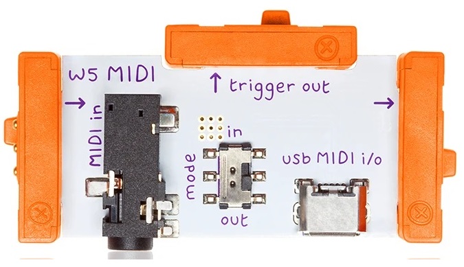
The MIDI module has a USB-B device port that presents itself to the USB-A host as a class-compliant MIDI device. The MIDI module supports both USB MIDI IN and USB MIDI OUT. However, the module operates in one mode (IN or OUT) at a time. The mode is selected by its mode switch (duh!).
- IN mode: Receives MIDI messages from the host.
- OUT mode: Sends MIDI messages to the host.
This blog post focuses on IN mode.
IN mode converts incoming MIDI note messages to two signals:
- Gated control voltage (gated CV)
- Trigger
Although littleBits call the digital output “Trigger,” it really is a gate signal, as we shall see.
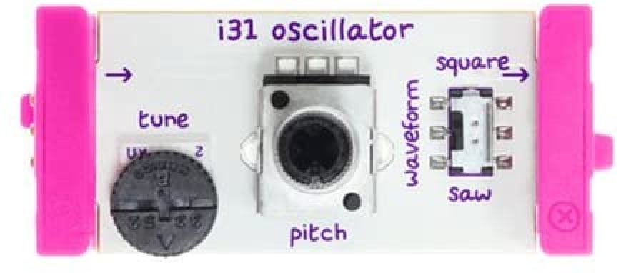
The littleBits Oscillator module is a pretty simple affair. The sole input is the (gated) control voltage which changes the pitch. The sole output is either square or saw wave as selected by the waveform switch.
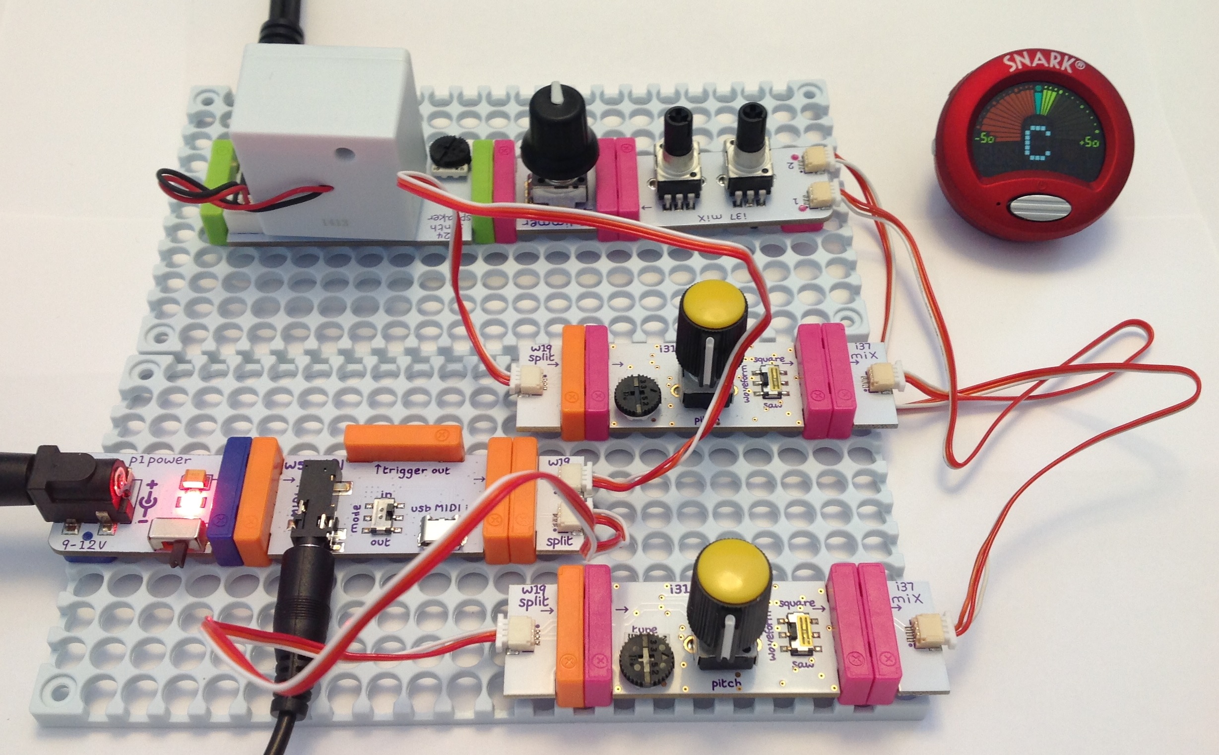
The test rig
Here’s my test and measurement approach.
The littleBits signal chain consists of a power module connected to the MIDI module which drives a littleBits oscillator module. I split the gated CV signal sending it to both the oscillator and a proto module. The oscillator output is sent to a speaker module, giving me aural feedback. Hey, is this thing on?
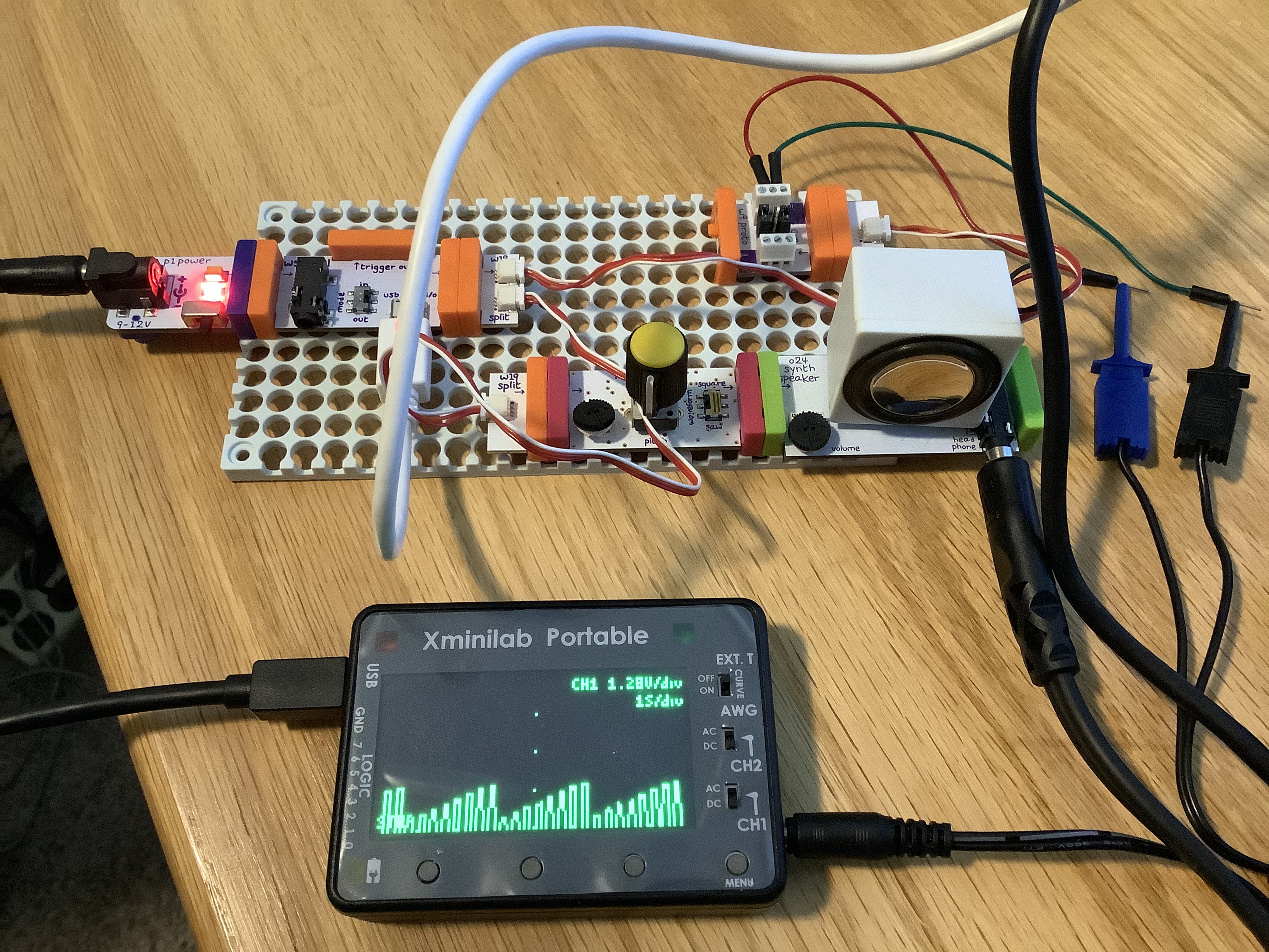
The GND and gated CV signal are sent from the proto module to a Gabotronics Xminilab oscilloscope. I attached another proto module to the MIDI module “trigger out.” The GND and “trigger out” from that proto module are went to the second channel of the oscilloscope. Thus, I can monitor both the gated CV and “trigger out” and see the timing relationships between the signals.
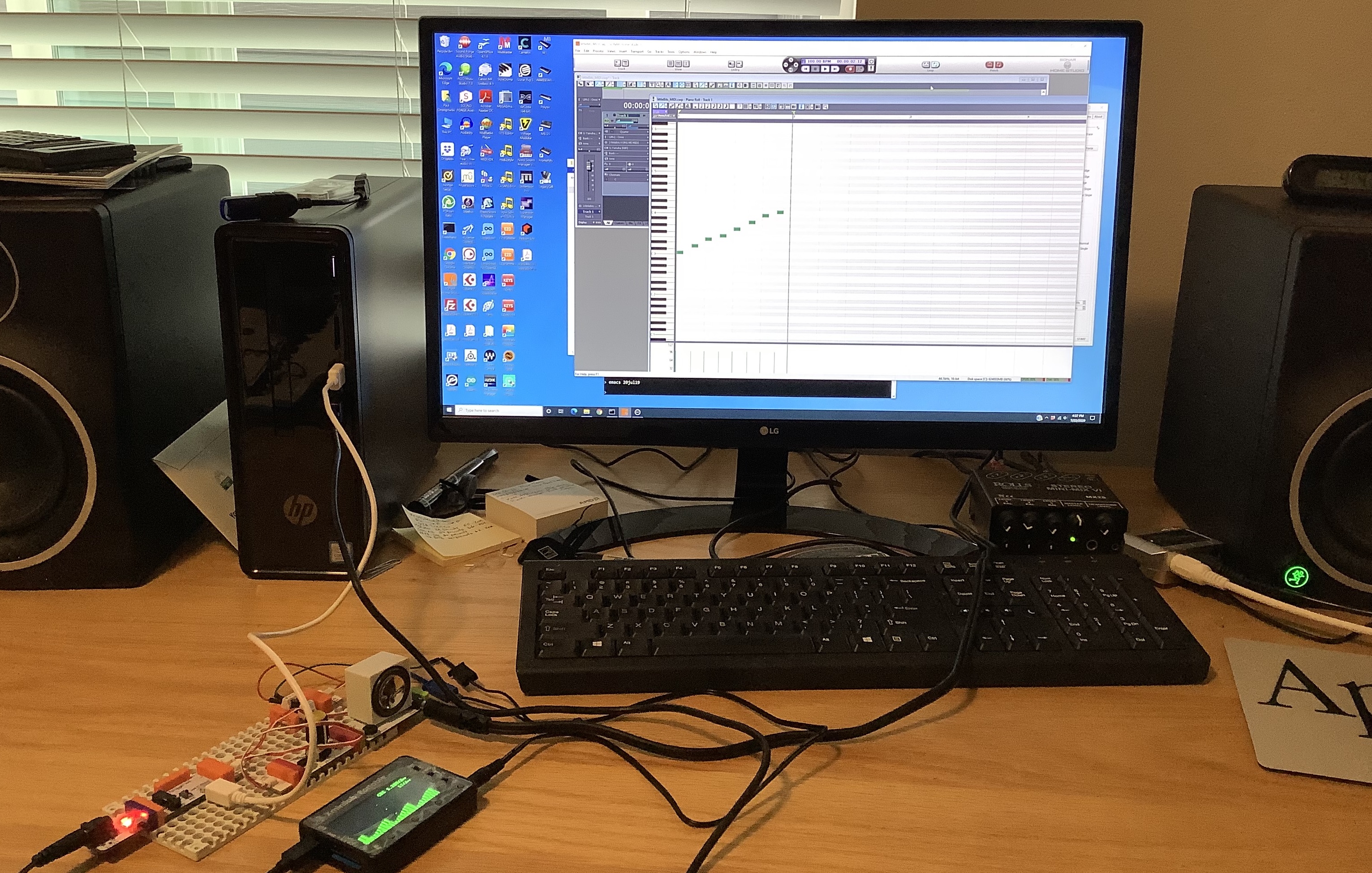
The Xminilab front panel user interface is a little fiddly. So, I connected the oscilloscope to a PC running the Gabotronix oscilloscope application. This arrangement makes it sooooo much easier to configure the oscilloscope and to capture screen shots.
The USB MIDI comes from the PC, too. SONAR generates MIDI messages and sends them to the littleBits MIDI module. Test messages are produced from a repeating one measure loop (80 BPM or so). The repeating loop gives me good repeatability.
The signals under test
As noted by other experimenters, littleBits combine gate with CV functionality. When the MIDI module receives a note ON message, it:
- Asserts the trigger signal, and
- Drives the gated CV output with a positive voltage proportional to the MIDI note number.
The MIDI note range is C2 to C6 (4 octaves). MIDI note C2 generates a gate CV voltage of 0.2 Volts. From there, the output voltage increases by 1 Volt per octave (1V/oct). Each semi-tone step increases the voltage by 1/12 Volts. The module asserts trigger by raising its output voltage to 5V.
When the MIDI module receives the corresponding note OFF message, it:
- Drops the trigger signal to 0V, and
- Drops the gated CV output to 0V.
Notice that the gated CV output is asserted and dropped in parallel with the trigger output. Trigger is always driven to 5V while the gated CV voltage is positive and is proportional to the MIDI note number.
The screenshot below illustrates the operation of these two signals. The top trace (green) is the gate CV voltage. The bottom trace (red) is the trigger voltage. [Click images to enlarge.]
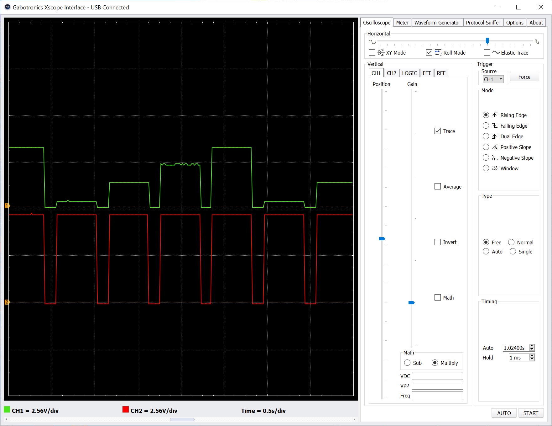
The MIDI test loop plays C2, C3, C4 and C5 in succession and repeats. The stair steps in the top trace show the effect of each successive note in the loop. The vertical display scale is 2.56V per grid division. You can see that each successive step is 1 Volt higher starting with C2 at 0.2V.
The trigger and gated CV traces are in temporal lock-stop, i.e., they rise and fall together. The width of the trigger signal is always the same width as the gated CV signal. Please recall that “trigger” in synth-speak is normally a fixed-width narrow pulse. That’s why I think the littleBits “trigger” signal is really a gate signal.
So, why do littleBits use a gated CV? Short answer: In conventional use cases, both gate and CV can be sent through a single wire (connection). The synthesist doesn’t have to route two separate wires (connections). The simplified wiring makes life easier for novice users (kids). The synthesist merely lines up a keyboard (sequencer, MIDI module) with an oscillator module and “it just works.” We will see other instances of the “It just works” philosophy in the envelope module, too.
C2, C3, etc. are MIDI note numbers and nice names. However, you’ll need to tune the Oscillator module to obtain the correct musical pitch.
Copyright © 2020 Paul J. Drongowski