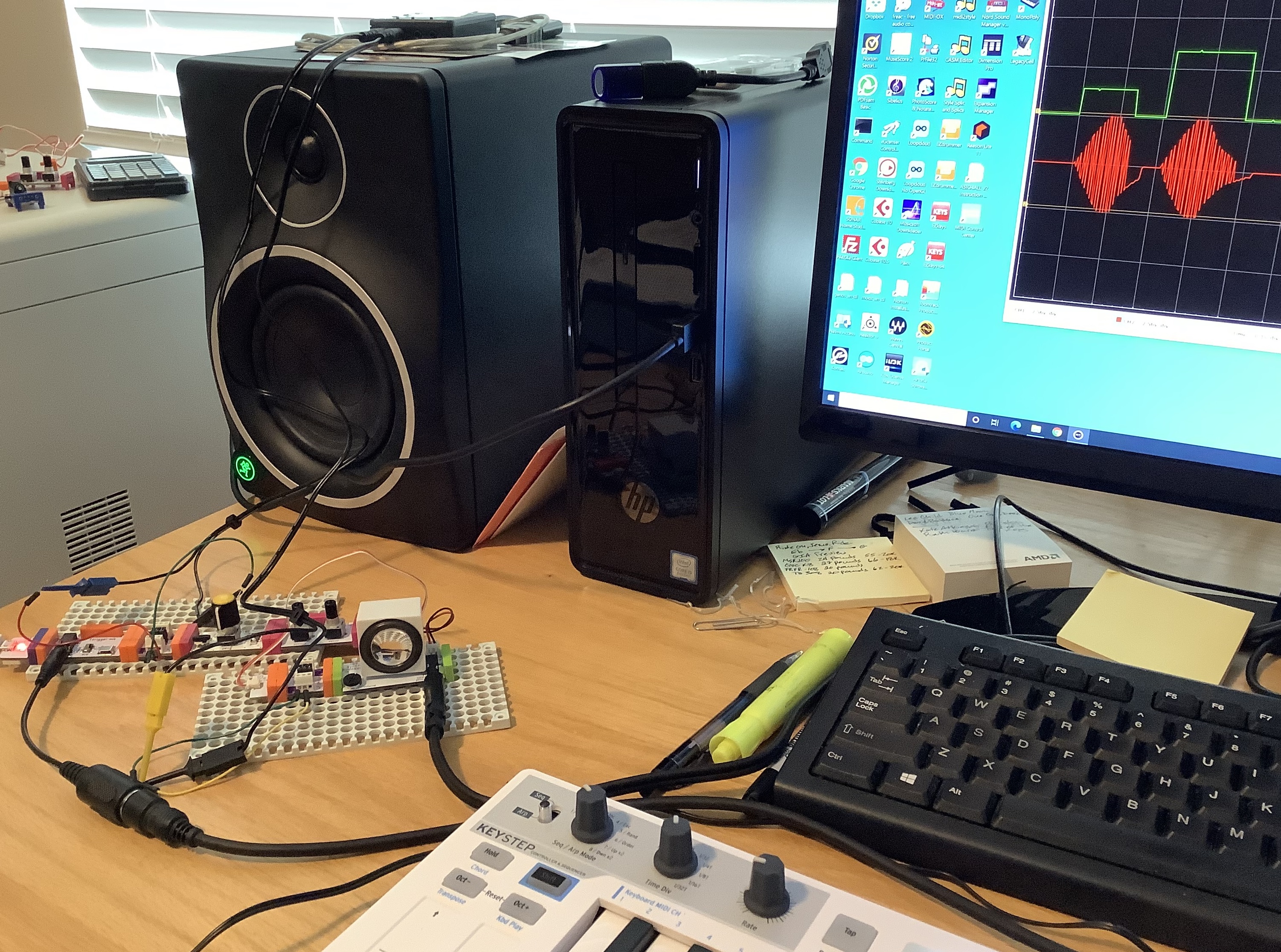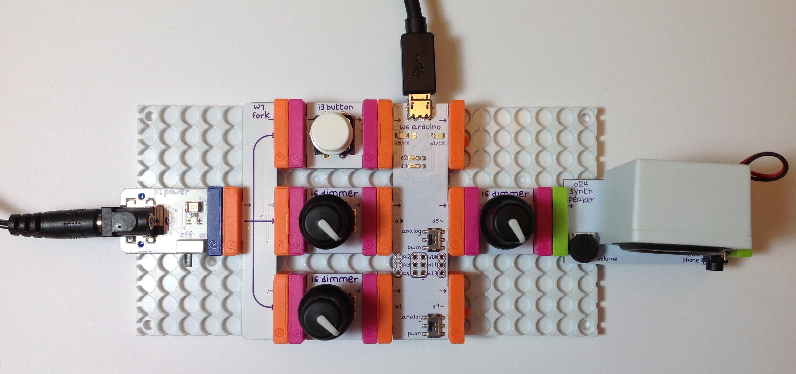
Here are a few experiments testing littleBits audio post-processing. In the first few cases, audio is produced by a Yamaha SHS-500 synthesizer fed into the LINE IN of a littleBits Microphone module. Outgoing audio is sent through a littleBits Speaker module connected to an external amplified speaker.
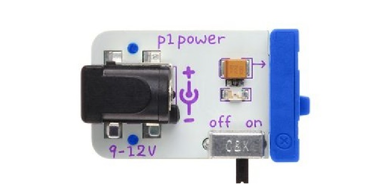
I did not draw the littleBits Power module into every example circuit. If you’re experimenting at home, hey, “One, Two, you know what to do…”
The first circuit filters incoming audio:
PowerSnap
|
V
Envelope <-- Button <-- PowerSnap
|
V
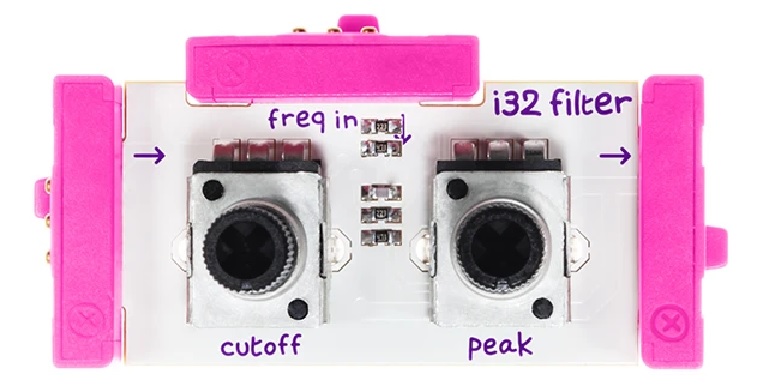
Mic --> Filter --> Speaker
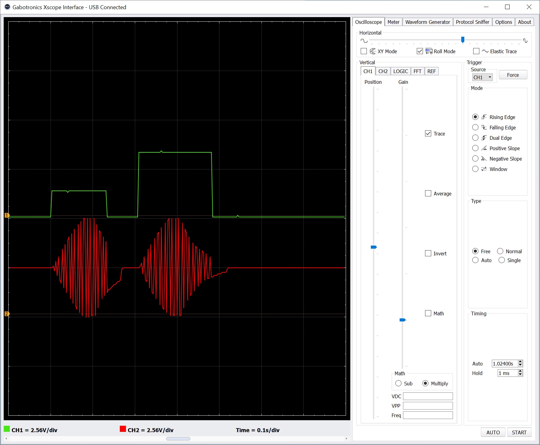
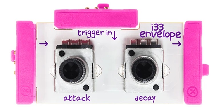
The Filter modulation input is driven by a littleBits Envelope module. The (audio) input of the Envelope is connected to a littleBits PowerSnap which supplies a constant +5 Volts to the input of the Envelope. A littleBits Button module is connected to the Envelope’s trigger input. (The second PowerSnap assures a full 5 Volt ON signal through the Button.) The Envelope sweeps from 0 to 5 Volts when the Button is pressed. Of course, the Envelope is shaped by its attack and release settings.
The first circuit operates successfully. The audio is filtered according to the Filter’s cut-off and resonance settings. The Filter quacks (a very scientific term!) when the Button is pushed.
The second circuit replaces the Button with a littleBits Pulse module:
          PowerSnap
              |
              V
           Envelope <-- Pulse <-- PowerSnap
              |
              V
    Mic --> Filter --> Speaker
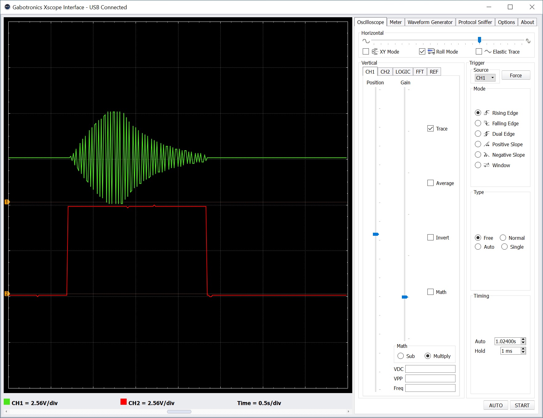
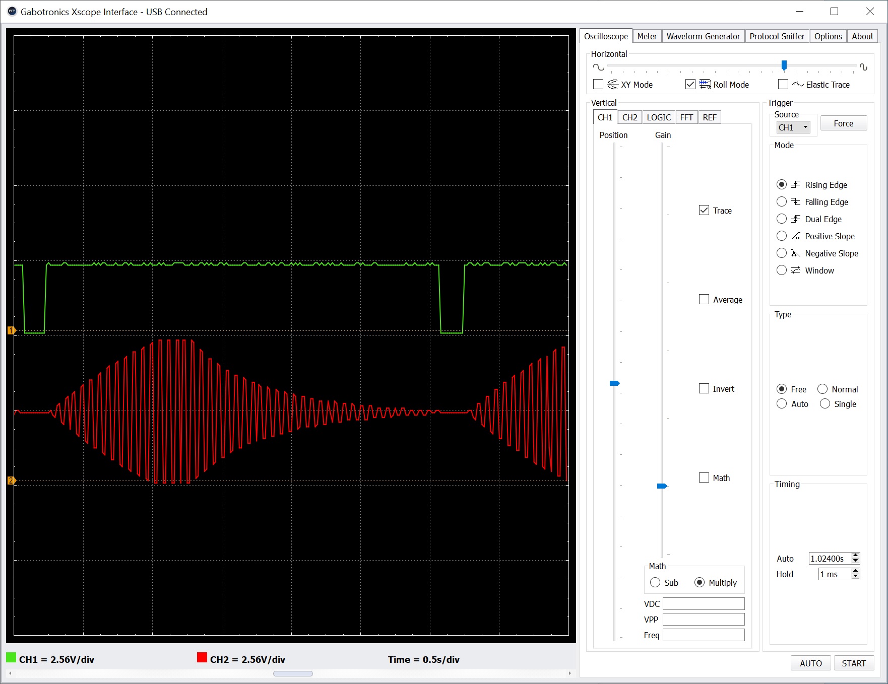
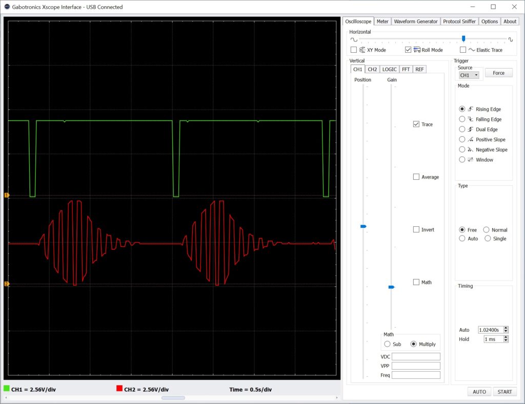
The Pulse module repeatedly sends a trigger signal to the Envelope module. The triggers cause the Filter to quack correctly. However, there is an audible click when the Pulse module fires — even if no audio is playing. This noise is unacceptible and I don’t know why it is occurring. Power glitches perhaps?
At this point, I began experimenting with the littleBits Threshold module. The (third) simple test circuit below:
Power --> Dimmer --> Threshold --> Number
demonstrated that my intuition about the Threshold behavior is correct: when the voltage into the Threshold exceeds the threshold setting, the Threshold turns ON and outputs +5 Volts. When the input voltage falls below the threshold setting, the Threshold output turns OFF (0 Volts).
Testing tip: The Number module has a “Voltage” setting in which Number displays the incoming input voltage. You can use a Number module as an in-circuit volt meter.
Given that, I couldn’t determine why the Threshold was not acting like a gate generator when driven by a littleBits audio signal, i.e., driven by the Microphone module in its “Sound” setting. Turns out, the littleBits Microphone module converts the incoming LINE IN signal into its own notion of audio — a signal centered around 2.5 Volts. I connected a Bargraph (or Number) module to the output of Microphone, and indeed, the Microphone sends 2.5 Volts when the audio is silent.
Arg! Once again bitten by the lack of signal documentation! When the Microphone is in its “Other” setting, it converts the input signal to swing from 0 to 5 Volts. Bad news, however. The Speaker module expects audio in the 2.5 Volt centered, littlebits convention and it distorts like a bandit when driven with the “Other” setting.
The 2.5 Volt convention also explains why some folks have observed only a 2.5 Volt sweep in the Envelope output. All of this has serious implications when mixing audio and control signals in littleBits. I need to think about this for a while…
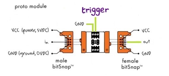
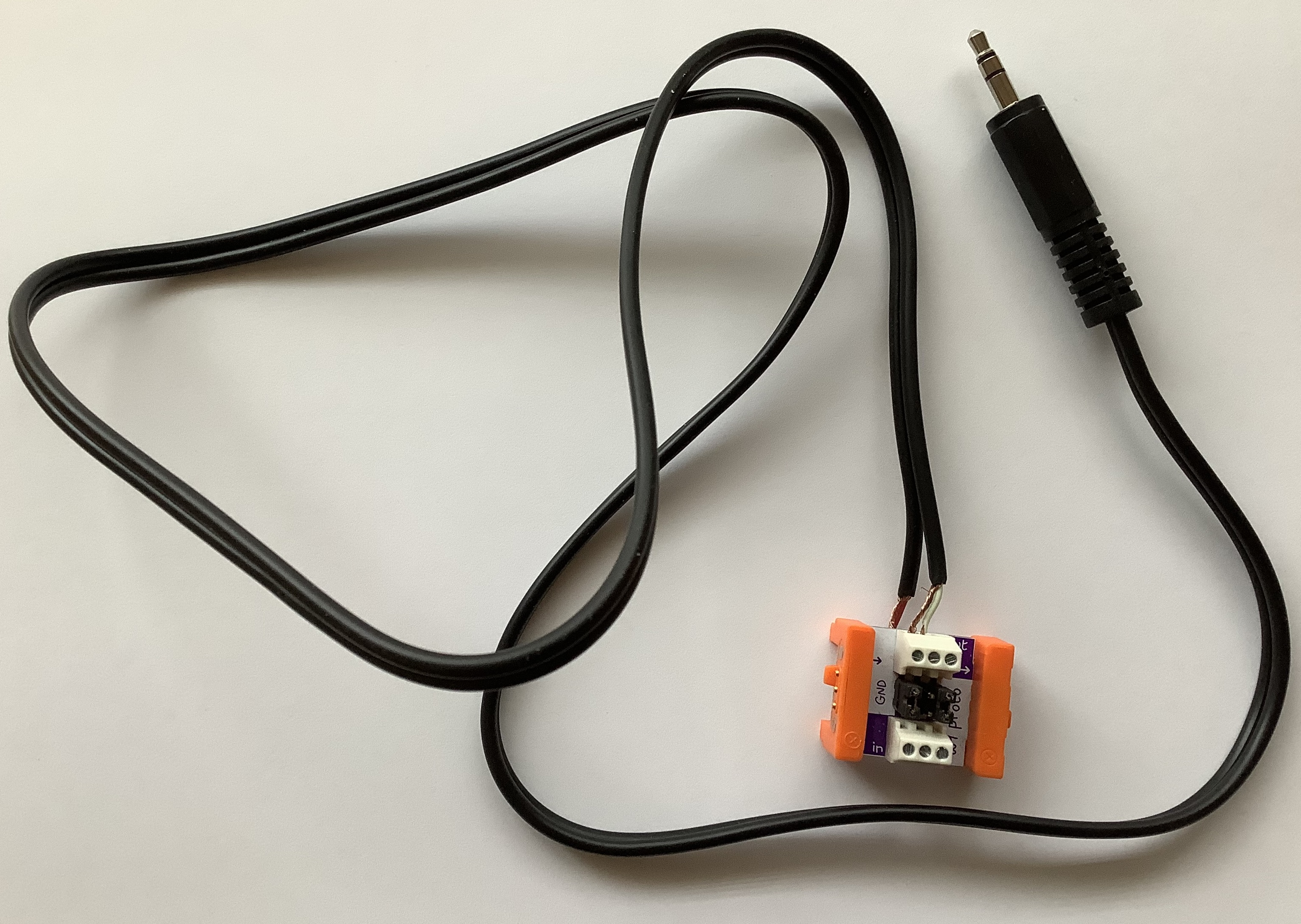
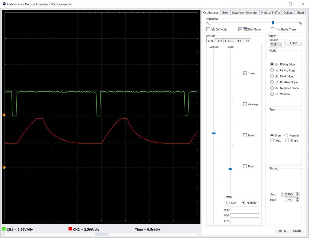
The fourth test circuit demonstrates filtering of regular line level audio:
                              Powered Speaker
                                  LINE IN
                                     |
    Power --> Proto --> Filter --> Proto
                |
           Synthesizer
            LINE OUT
This circuit filters incoming audio. Fortunately, the 2.5 Volt convention does not preclude a simplified signal chain, that is, a chain omitting the littleBits Microphone and Speaker modules. A filter is a filter is a filter, I guess.
Although the Filter module operates on a “regular” audio signal, the Delay module does not. Substituting the Delay module into the fourth test circuit produces nasty noise and a whine. It will process the audio (you can hear repeats, etc.), but the noise/whine is horrible. Screams like a banshee. Bummer.
Bottomline, the littleBits Filter module has potential as an add-in for a PSS-A50 mod (or any other mod) without Microphone and Speaker modules. The littleBits Delay is simply too noisy by itself; one needs the Microphone and Speaker to perform signal conversion. As to the Filter, I need to explore alternatives for modulation. Experiments with using the Oscillator module as an LFO were underwhelming. So far, I haven’t successfully cobbled together an envelope following or audio-trigger envelope. Stay tuned.
Interested in littleBits synth control signals?
Copyright © 2021 Paul J. Drongowski