littleBits Arduino: More observations

Back with a few more quick observations as I get started with the littleBits Arduino module. (Please see my first review.)

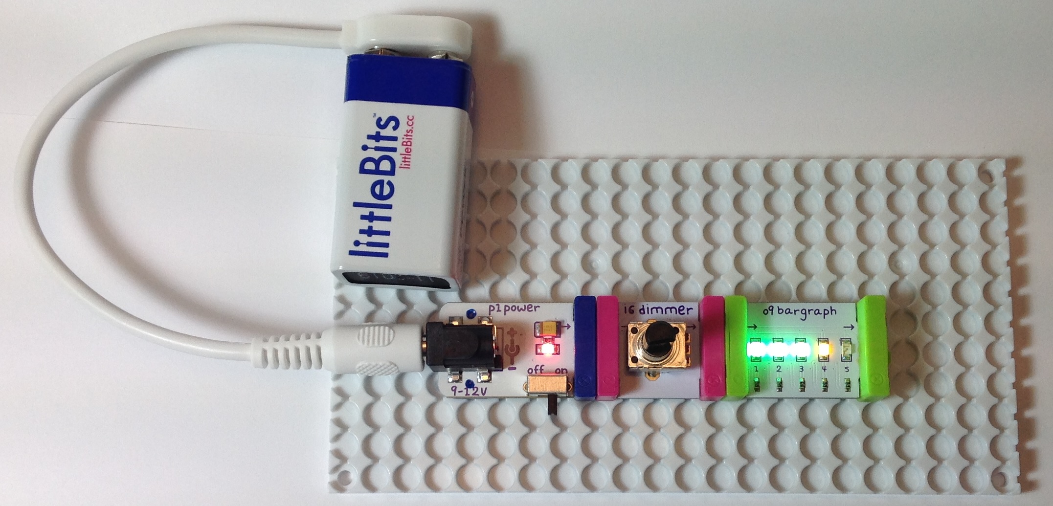
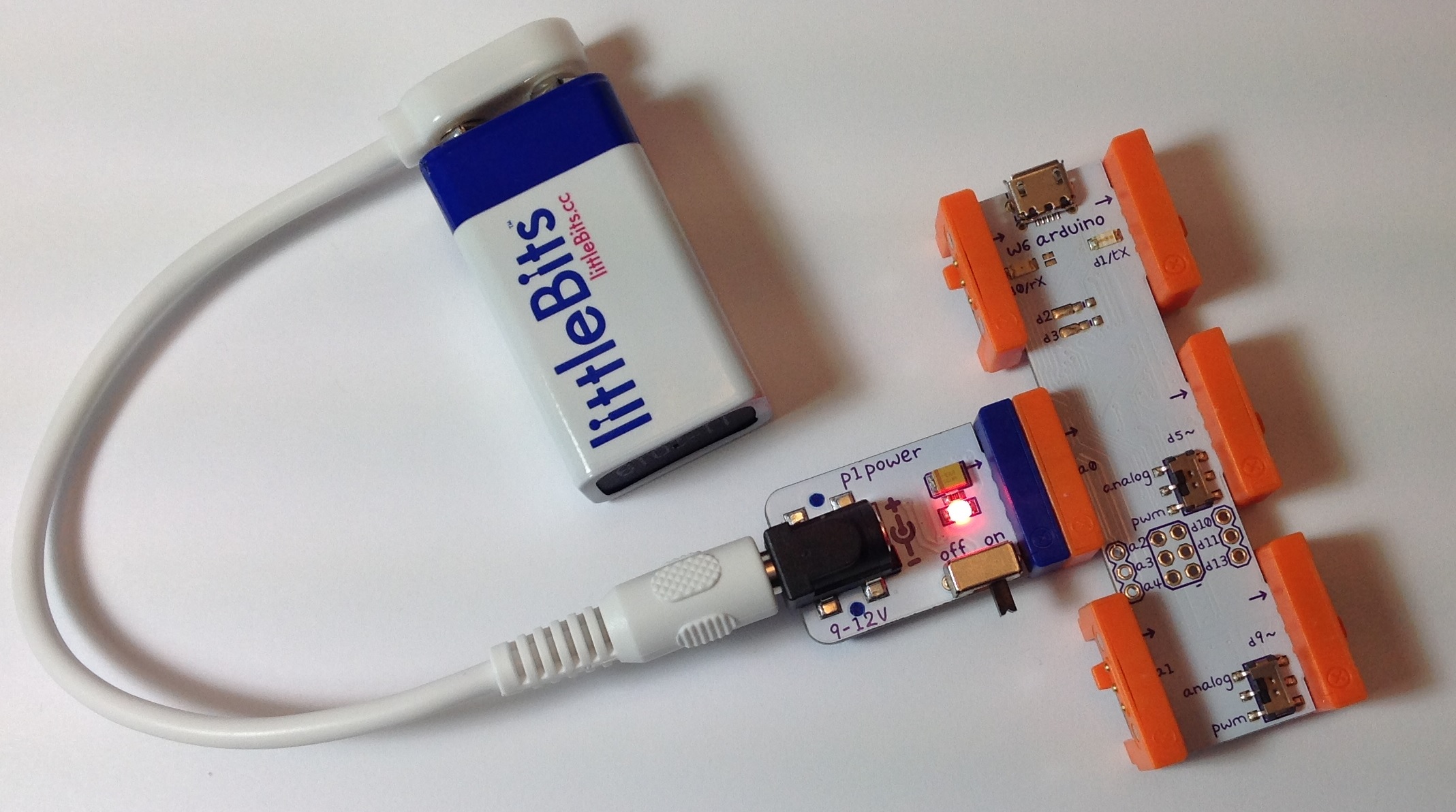
I decided to see how much stuff I could cram around the littleBits Arduino. (Click on the image below for full resolution.) This configuration starts with the power module on the left hand side. The power module is connected to a 9V 1500mA (1.5A) center positive power adapter with a 2.1mm plug. As I mentioned in my previous post, this is the same adapter that I use with my Arduino UNO. Already, I like the power switch on the power module — a very handy touch.

arduino_full_up

The power module drives three input modules (a button and two dimmers) via the fork module which is included in the Arduino Development Kit. The button module is connected to Arduino digital input D1 and the dimmer modules are connected to the Arduino analog inputs A0 and A1.

The Arduino D5 output is connected to a dimmer module that adjusts the volume (amplitude) of the signal sent to the synth speaker module. Yep, the synth speaker module has a volume control of its own. It’s that little trim pot in the lower left corner of speaker module. I find it difficult to adjust the tiny trim pot. Trim pots are designed for “set and forget” applications and have a limited rotational life (number of cycles). So, I splurged and inserted a dimmer module on the input to the speaker module.

I love the bargraph. You can use it as a poor man’s volt meter or logic indicator. I connected the bargraph module to Arduino output D9. Before I forget, the switches for D5 and D9 are set to the “analog” position.

I didn’t connect anything to Arduino digital output D1. A good first sketch would be blinking the on-board D1 LED on and off. So, I left the bitSnap empty.

The knobs on the dimmer modules are my own doing. The knobs do not come with the dimmer modules. I have a dozen or so of these basic knobs. The equivalent knobs are:

  • Multicomp CR-BA-7C6-180D ($0.35 per knob through MCM Electronics)
  • Sparkfun COM-08828 (now retired)

Knobs just make life easier and make things a little more dressed up.

I was hoping that littleBits had preloaded a sketch to the Arduino module and they did. The preloaded sketch makes the bargraph “breathe.” The sketch repeatedly ramps up the output voltage from zero volts to the MAX (5 volts) and ramps the voltage back down to zero volts. The dimmer connected to A1 controls the ramping speed, i.e., how fast the bargraph breathes.

I wish that littleBits made the preloaded sketch available on their web site. I couldn’t find it. Quite frequently, it’s handy to have a known-good sketch for testing purposes. I’m a stickler for testing and diagnostic programs. Too much emphasis on coding, not enough emphasis on testing, I say.

The littleBits site has a good introduction to installing and using the Arduino Integrated Development Environment (IDE). If you’re confused about the “analog” and “pwm” switch settings, be sure to scroll down into the comments section on this page. There is a good explanation. A short bit of advice: If you need to send an analog signal that varies anywhere from 0 to 5 volts, then put the switch into the “analog” position. If you need to send a purely digital signal (ON: 5V, OFF: 0V), then put the switch in the “pwm” position. (A pulse chain is, of course, a type of digital signal.)

If you’ve taken a look at the Arduino module schematic, you know that the switch enables (or disables) two extra stages of low pass filtering. The low pass filters (when enabled) generate an analog signal by smoothing out a PWM signal. This is essentially a poor man’s digital to analog converter (DAC) although it isn’t very hi-fi.

The littleBits web site has ten sketches to get you started. This part of their site could use a little polishing. First, I couldn’t find the source code for the sketches! At last, I realized that the link to a sketch is under the “ADDITIONAL FILES” section on the right hand side of the page — beneath the relatively huge “ADD ALL TO CART” button. Ah, sales before service. Beginning users may not realize that this is the link to the code. They may not know that the “ino” file extension refers to an Arduino IDE code file! Maybe kids are less confused than adults, but details like this could easily turn off a youngster who is lacking self-confidence.

The sketch file names are a little whack and don’t always directly refer to the section or page titles on the sketch web pages. Here is a correspondence table that I put together:

Example                     Source code file
--------------------------  ------------------------------
Blink                       blink.ino
Hold An On/Off State        buttonRead_stateChange.ino
Blink Speed Control         analogRead_digitalOutput.ino
LED Fading Effect           analogRead_analogOutput.ino
Servo Sequence Recorder     Sequence_Recorder_Starter.ino
DIY Etch A Sketch           etchasketch_arduino.ino
Analog Pong                 analog_pong_arduino.ino
DIY Computer Mouse          mouseMoveNClick.ino
Play A Melody               toneMelody.zip
Change The Pitch            tonePitchFollower.ino

Again, littleBits need to reduce the frustration barrier especially since kids are involved or teachers who have suddenly been assigned to computer science.

In my first review, I mentioned how mounting boards are essential for building mechanically robust and electrically reliable littleBits systems. Definitely true. However, littleBits still have room for improvement. The current mounting boards have quite a bit of flex in them and the pegs still pop out easily. I had a heck of a time getting the system (pictured above) to stay firmly put in the mounting board. It’s takes a lot of pressure to get a big system into a mounting board. I’m afraid that the pressure will weaken the board connections. Perhaps things will get better with practice or use…

If you’re interested in the backstory about the littleBits Arduino module, then read this article.

littleBits: First review

Some things are inevitable…

I taught undergraduate and graduate hardware design for many years. It was always a challenge to give students hands-on experience with digital logic circuits, especially for large-scale digital systems. Gosh, I could write several long blog posts that recount the various breadboarding, prototyping and simulation approaches that my students used in the lab. Along with the achievements came many horrors.

So, picking up littleBits was inevitable.

littleBits are so cute. Just in case you’ve been in an isolated cave, littleBits modules are small building blocks with magnetic “bitSnaps” at opposing ends. The magnetic bitSnaps sort the ports into inputs and outputs, and enforce an output-to-input connection rule. Each bitSnap carries the positive voltage rail, the ground rail and a signal. (Click images to get full resolution.)

dimmer_bargraph

The littleBits range covers basic digital logic and analog building blocks including audio. The Synth Kit — designed in collaboration with Korg — has perhaps done the most to promote widespread discovery and use of littleBits. The Synth Kit certainly placed littleBits in relatively non-traditional hands and sources, namely, musicians and musical instrument retailers. Before their recent bankruptcy proceedings, one could find individual ‘Bits in Radio Shack stores.

According to the manager of a local Radio Shack, the littleBits suffered a very high theft rate. Shame on anyone who unlawfully filched these!

Most retailers today (like Barnes and Noble bookstores) sell littleBits kits. The kits make it easier for people to get started and it reduces the number of separate SKUs at point-of-sale. With Radio Shack’s reorganization, these days, it is more difficult to buy individual modules a la carte. The littleBits on-line shop carries the full range, of course. Still, one rarely finds ‘Bits or kits at a discount.

The kits are also a little less easy to steal although a Barnes and Noble shopkeeper acknowledged high theft potential, too. Stop stealing!

One reason why people may feel entitled to boost littleBits with sticky fingers is their perceived expense. An LED at $7.95 may seem grossly overpriced. However, each individual module has at least two bitSnaps and there is value-added design and electronics on board. The LED module, for example, has a voltage protected input and a driver. In fact, all signals in the littleBits series are driven and normalized; that’s what makes them special. If all you want is a naked LED with two leads, then by all means pass up littleBits and try something else!

Signal standardization is what makes littleBits what they are. littleBits are very close to the plug-and-play electronic LEGO™ blocks that educators have wanted for a zillion years.

I decided to forego prepackaged kits and buy a la carte. The kits usually have modules which I probably won’t use and it just seems like a waste to buy them. That includes the Synth Kit, too. (Are you surprised?) I don’t have any interest in the tiny keyboard or the sequencer. I’m not that interested in the oscillators for that matter. I want to drive my synth and other experiments with Arduino. Thus, the only kit that I have purchased is the Arduino Coding Kit. Everything in this kit is quite useable with the exception of the servo module. (Although a Neil Young Whizzer would be a unique project!)

The littleBits Arduino board is a good example of value-added engineering. Sure, the Arduino ‘Bit doesn’t provide all of the ins and outs of a stock Arduino UNO, for example. However, the bitSnap signals are standardized with protection on the inputs and (switchable) low pass filters on the PWM outputs. The serial transmit (TX) and receive (RX) signals are made available through bitSnaps, making MIDI IN and OUT a future possibility. Programming is supported through either USB or ICSP. You’ll need to add header pins for ICSP, but if you’re using ICSP, you already ride tall in the saddle.

arduino_battery

I intend to whip up MIDI IN and MIDI OUT circuits using PROTO modules. I thought long and hard about the options. The Hardware Development Kit contains two PROTO modules, one PERF module and 12 bitSnaps (6 male, 6 female). I am not a fan of pad-per-hole perf board, so the PERF module is not that attractive to me. I much prefer “DIP style” prototyping boards that accomodate full size, through hole DIP ICs. This is sooooo much easier to solder. For similar reasons, I’m not sure that I want to fiddle around crafting circuit boards to conform to the bitSnaps. Overall, I will probably buy two PROTO modules a la carte.

The littleBits web site is a little sketchy on certain vital details:

  • The Arduino board USB port is a micro USB port.
  • The power module can be driven by a 9V, center positive, 2.1mm power adapter — the same as an Arduino UNO.
  • The power module can drive any input bitSnap (any port in a storm).
  • The Arduino IDE should be configured for the Leonardo board.

I don’t like hunting around for this kind of information and I especially do not want to watch videos to find it! In fact this information should be printed on the plastic purple baggy containing the Arduino board. (Also, the link to Arduino sketches on the current baggy is dead.)

Thank goodness that the Arduino Development Kit comes with two mounting boards. A mounting board holds a littleBits circuit in place and makes connections reliable. I whipped together a simple circuit without using a mounting board and the relatively heavy adapter cable kept pulling the power module away from the other boards. The bitSnap magnets are simply not that big and strong. Programming and using an Arduino module without a mounting board would be a nightmare.

So far, a favorable, somewhat vanilla review. Here’s a bit of my own value-added as a computer science educator.

When I first powered up the pulse module — a 555 timer-based circuit that generates a regular stream of digital pulses — I didn’t necessarily see a clock. I saw a token generator. I thought, “Given the current design of the logic elements, wouldn’t it be neat to build and visualize a one-hot state machine (controller)?” If each latch module had a built-in LED showing the state of the latch, this application would be a natural for littleBits.

Even better, why not bag synchronous control altogether and go asynchronous, self-timed?

Ivan E. Sutherland, Turing Award paper, Communications of the ACM, Volume 32, Number 6, June 1989, pages 720-738. And don’t forget everything written by Chuck Seitz, too!

This immediately raises the question of what we want students to learn from their experience with littleBits. I want students to learn that:

Electronic systems are inherently parallel.

Students need to be exposed to concurrency and parallelism before their minds are corrupted by the sequential, synchronous paradigm in conventional programming languages.

The other question that pops up is scalability. littleBits logic elements currently operate at the bit level. However, I’d love to have modules at the bus level such that students could build their own CPUs, GPUs, whatever. Plug-and-play busses are a tougher design challenge electrically and mechanically. One possible solution is to transmit data words serially from module to module. Pass the word size along with the data in order to simulate any (reasonable) bus width. littleBits could then keep the current bitSnap form factor.

Finally, I would like to mention the module technology that gave me a start in digital electronics: DEC Register Transfer Modules, also called the “PDP-16” or “RTMs.” RTMs use a flowchart-like notation for control design. This approach opened a whole world to me including ISP, Petri Nets and eventually dataflow computing. Most importantly, RTMs taught my 19 year-old mind that computation is fundamentally parallel and we should design for and exploit concurrency right from the get-go. Nico Habermann, God bless him, did the same in the sophomore programming course at C-MU. This point of view influenced my entire professional life!

If you would like to know more about RTMs, then read “Designing Computers and Digital Systems Using PDP-16 Register Transfer Modules,” by C. Gordon Bell, John Grason and Allen Newell, 1972. I was one of the first guinea pigs to use RTMs in the computer design course taught by John Grason. Thanks, John!

See also “The Description and Use of Register-Transfer Modules,” C. Gordon Bell, J.L. Eggbert, J. Grason, and P. Williams, IEEE Transactions on Computers, Volume C-21, Number 5, May 1972, pages 495-500.