
My last blog post took a look at the Pitch and Gate control voltages (CV) generated by the Arturia Keystep. Keystep’s Pitch and Gate behave conventionally. I also took note of how they differ from the littleBits gate CV signal, which combines pitch and gate control into a single signal. I mentioned two potential approaches for interfacing Keystep to littleBits:
- Driving littleBits with Keystep’s Pitch and Gate, and
- Sending MIDI to a littleBits MIDI module that handles conversion to littleBits gated CV.
I tried each approach. Here’s what I learned.
Keystep Pitch and Gate circuit
In this approach, the littleBits Oscillator is always running, always generating an audio signal. The Oscillator tracks the Gate voltage generated by the Keystep. The trick is opening up and shutting off the audio signal. For that, I put a littleBite Envelope module after the Oscillator and triggered the Envelope with the Keystep Gate voltage.
The resulting circuit is:
            Keystep Pitch                Keystep Gate
                  |                           |
                  V                           V
    Power --> CV Module --> Oscillator --> Envelope --> Speaker
The Keystep Pitch output is connected to the “CV IN” connector on the CV Module. The CV Module routes the incoming control voltage to its output, which sends the pitch control voltage to the Oscillator Module. The Keystep Gate output is connected to the Envelop’s Trigger input.
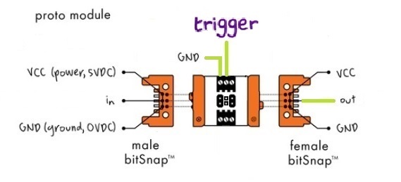
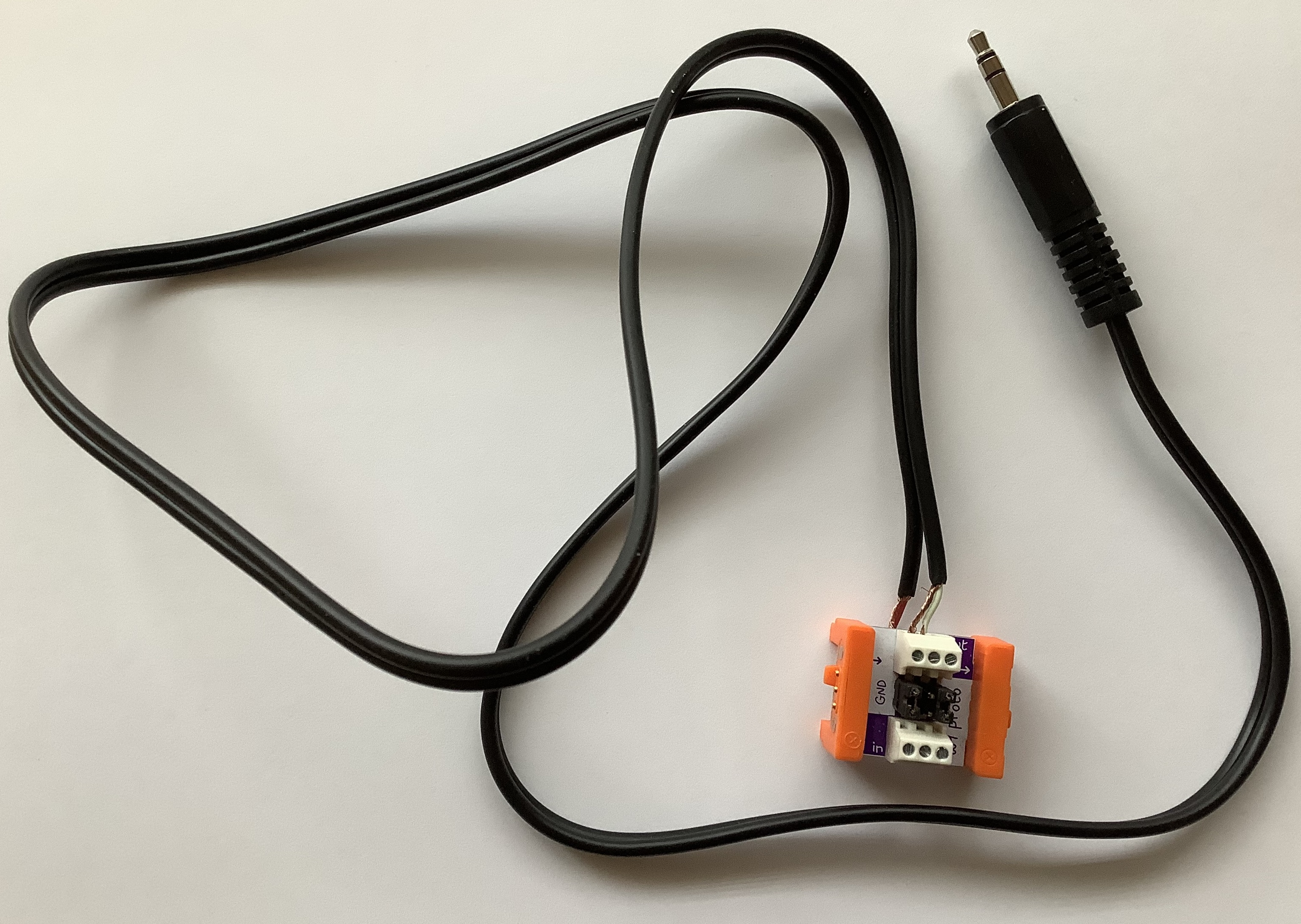
The Pitch output to CV IN connection is a standard 3.5mm patch cable. But, how is the 3.5mm Gate jack connected to the Trigger bitSnap? The littleBits Proto Module provides the solution. I cut a (stereo) patch cable in two and connected the shield and tip wires to the littleBits Proto Module as shown above. The Proto Module sends the incoming trigger signal (the Keystep Gate) to the output bitSnap. From the output bitSnap, the trigger signal goes to the Envelope Trigger input.
Properly, I should have used a mono patch cable, but I didn’t have one to sacrifice. I connected the TIP and SHIELD wires, leaving the RING unconnected.
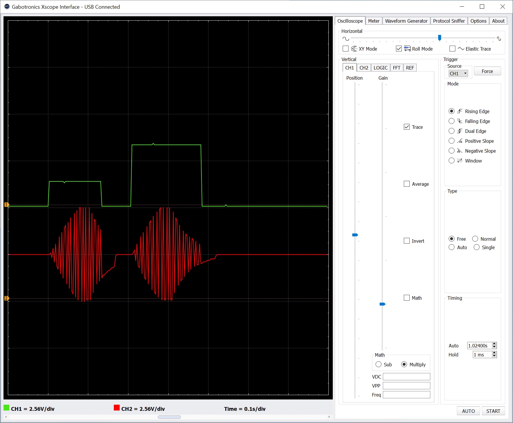
That’s the entire setup! For testing purposes, I attached oscilloscope probes to the trigger (Keystep Gate) and the Envelope’s audio output. I also verified correct operation at intermediate points along the main signal path.
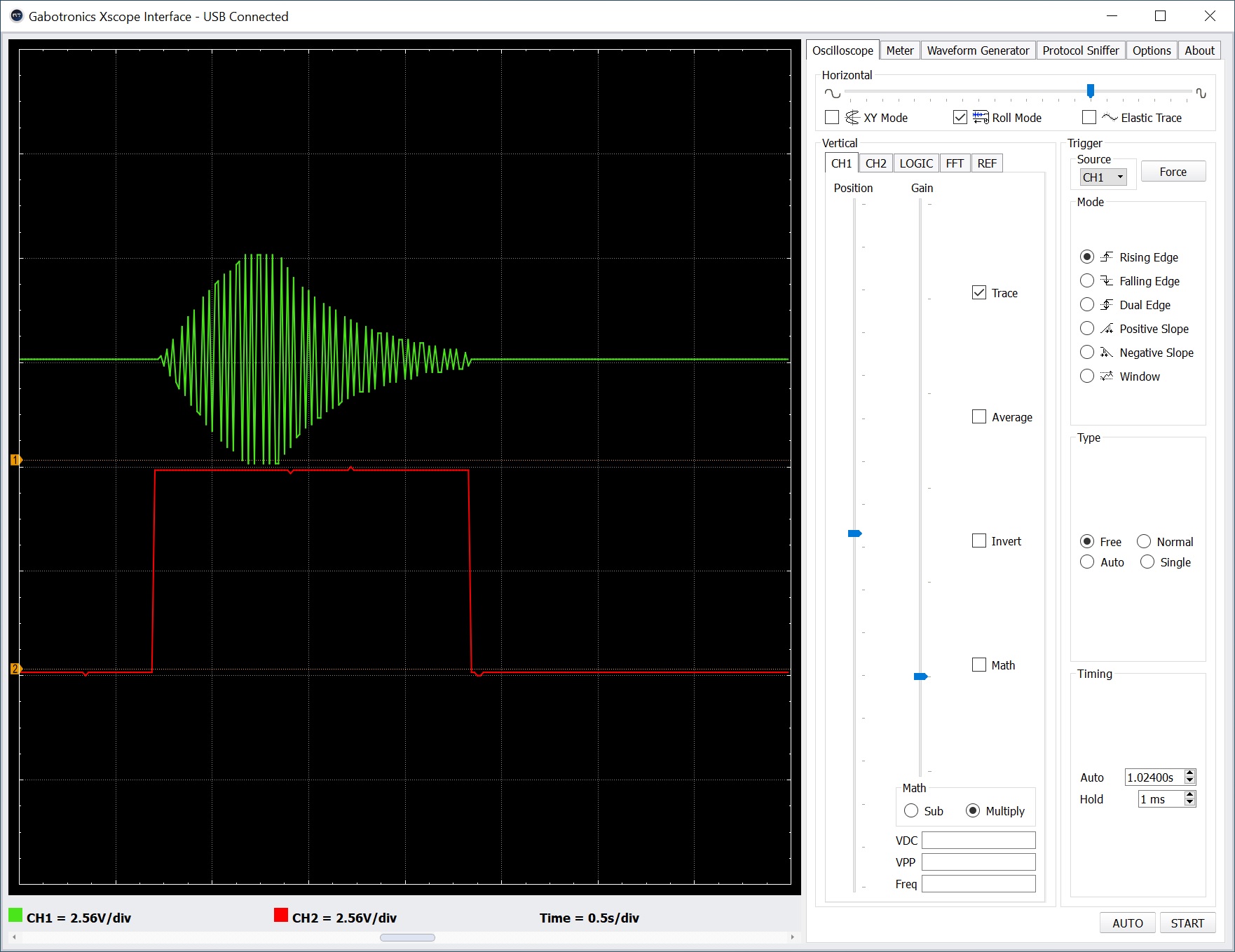
The screenshot above shows two oscilloscope traces. The top trace (green) is the final audio signal. Note the attack-release envelope around the oscillator signal. The bottom trace (red) is the trigger (Keystep Gate) signal. If the trigger is dropped before the entire envelop completes, the audio cuts off (i.e., it’s truncated). If the trigger is held beyond the combined attack plus release time, the audio signal merely stays at zero. The audio signal remains shut off until another trigger (the rising edge of Gate) is received.
Although this circuit gives us the desired behavior, it wasn’t easy getting things to work reliably. I seemed to suffer more than the usual loose connections and other lab-bench gremlins.
MIDI Module circuit
The MIDI Module approach is very similar to driving the littleBits Oscillator Module by MIDI over USB from a PC DAW:
           Keystep MIDI OUT
                   |
                   V
    Power --> MIDI Module --> Oscillator --> Envelope --> Speaker
MIDI arrives on the MIDI Module’s 3.5mm connector instead of the USB port. Otherwise, the main signal flow is the same.
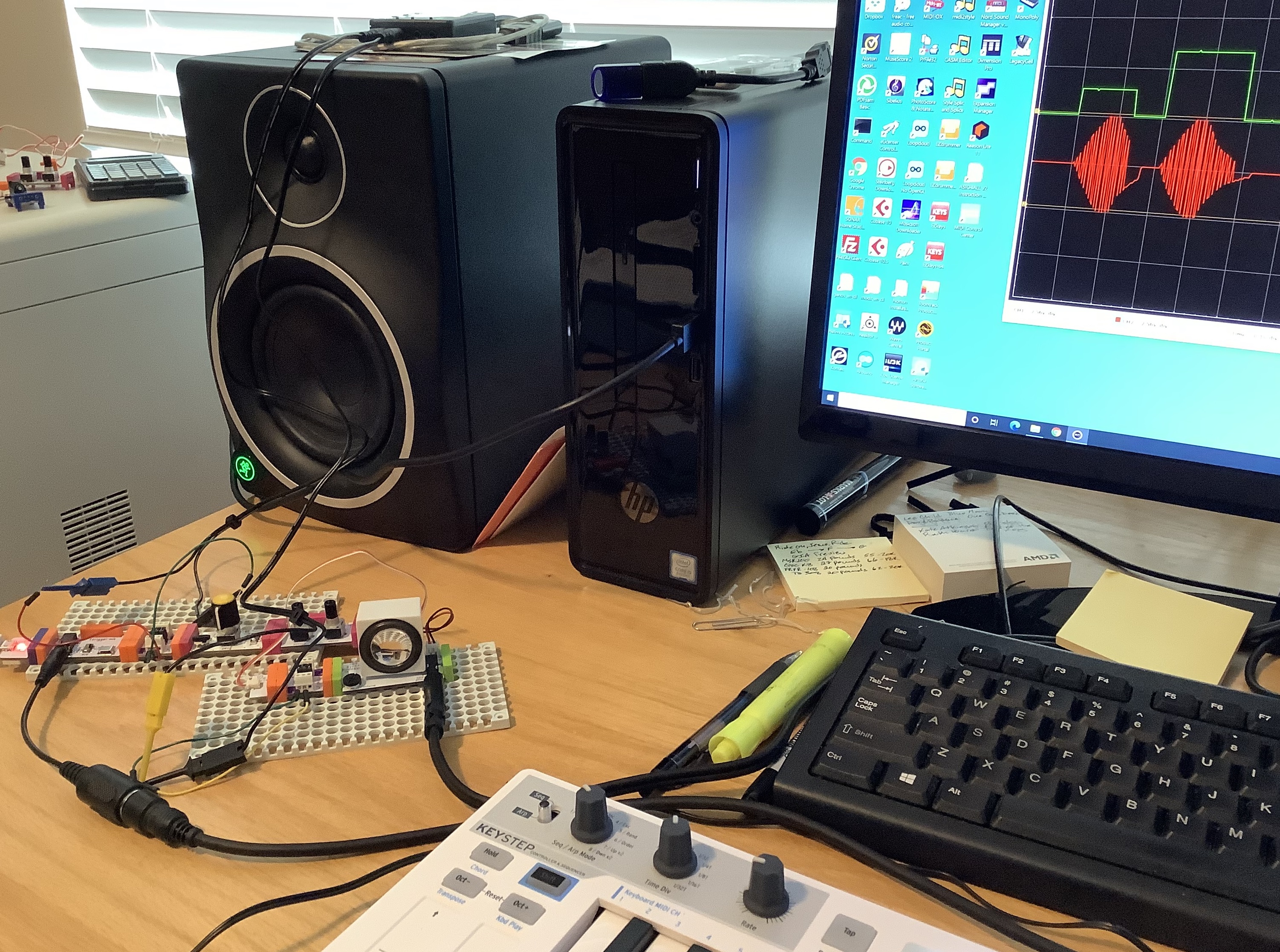
I monitored the gated CV signal produced by the MIDI Module and the audio signal generated by the littleBits Envelope using the oscilloscope. I played two notes in quick succession. The second note is two octaves higher than the first note.
In the screenshot above, the top oscilloscope trace is the gated CV signal. The bottom trace is the synthesized audio. Not any different than the Pitch and Gate control volltage approach, eh?
Since the final audio is much the same, I would go with the MIDI Module circuit. It is simpler and its wiring is less touchy. The circuit uses the littleBots modules pretty much as intended by the littleBits engineers.
The MIDI Module approach makes the Keystep Pitch, Gate and MOD outputs available for other duties such as key-scaling (i.e., varying the effect of a sound modifier by keyboard pitch), modulation and user control. Don’t forget to insert littleBits Dimmer Modules (potentiometers) along control paths in order to set modulation level and so forth.
Copyright © 2020 Paul J. Drongowski