Back with a few more quick observations as I get started with the littleBits Arduino module. (Please see my first review.)
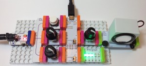
I decided to see how much stuff I could cram around the littleBits Arduino. (Click on the image below for full resolution.) This configuration starts with the power module on the left hand side. The power module is connected to a 9V 1500mA (1.5A) center positive power adapter with a 2.1mm plug. As I mentioned in my previous post, this is the same adapter that I use with my Arduino UNO. Already, I like the power switch on the power module — a very handy touch.
The power module drives three input modules (a button and two dimmers) via the fork module which is included in the Arduino Development Kit. The button module is connected to Arduino digital input D1 and the dimmer modules are connected to the Arduino analog inputs A0 and A1.
The Arduino D5 output is connected to a dimmer module that adjusts the volume (amplitude) of the signal sent to the synth speaker module. Yep, the synth speaker module has a volume control of its own. It’s that little trim pot in the lower left corner of speaker module. I find it difficult to adjust the tiny trim pot. Trim pots are designed for “set and forget” applications and have a limited rotational life (number of cycles). So, I splurged and inserted a dimmer module on the input to the speaker module.
I love the bargraph. You can use it as a poor man’s volt meter or logic indicator. I connected the bargraph module to Arduino output D9. Before I forget, the switches for D5 and D9 are set to the “analog” position.
I didn’t connect anything to Arduino digital output D1. A good first sketch would be blinking the on-board D1 LED on and off. So, I left the bitSnap empty.
The knobs on the dimmer modules are my own doing. The knobs do not come with the dimmer modules. I have a dozen or so of these basic knobs. The equivalent knobs are:
- Multicomp CR-BA-7C6-180D ($0.35 per knob through MCM Electronics)
- Sparkfun COM-08828 (now retired)
Knobs just make life easier and make things a little more dressed up.
I was hoping that littleBits had preloaded a sketch to the Arduino module and they did. The preloaded sketch makes the bargraph “breathe.” The sketch repeatedly ramps up the output voltage from zero volts to the MAX (5 volts) and ramps the voltage back down to zero volts. The dimmer connected to A1 controls the ramping speed, i.e., how fast the bargraph breathes.
I wish that littleBits made the preloaded sketch available on their web site. I couldn’t find it. Quite frequently, it’s handy to have a known-good sketch for testing purposes. I’m a stickler for testing and diagnostic programs. Too much emphasis on coding, not enough emphasis on testing, I say.
The littleBits site has a good introduction to installing and using the Arduino Integrated Development Environment (IDE). If you’re confused about the “analog” and “pwm” switch settings, be sure to scroll down into the comments section on this page. There is a good explanation. A short bit of advice: If you need to send an analog signal that varies anywhere from 0 to 5 volts, then put the switch into the “analog” position. If you need to send a purely digital signal (ON: 5V, OFF: 0V), then put the switch in the “pwm” position. (A pulse chain is, of course, a type of digital signal.)
If you’ve taken a look at the Arduino module schematic, you know that the switch enables (or disables) two extra stages of low pass filtering. The low pass filters (when enabled) generate an analog signal by smoothing out a PWM signal. This is essentially a poor man’s digital to analog converter (DAC) although it isn’t very hi-fi.
The littleBits web site has ten sketches to get you started. This part of their site could use a little polishing. First, I couldn’t find the source code for the sketches! At last, I realized that the link to a sketch is under the “ADDITIONAL FILES” section on the right hand side of the page — beneath the relatively huge “ADD ALL TO CART” button. Ah, sales before service. Beginning users may not realize that this is the link to the code. They may not know that the “ino” file extension refers to an Arduino IDE code file! Maybe kids are less confused than adults, but details like this could easily turn off a youngster who is lacking self-confidence.
The sketch file names are a little whack and don’t always directly refer to the section or page titles on the sketch web pages. Here is a correspondence table that I put together:
Example                     Source code file
--------------------------  ------------------------------
Blink                       blink.ino
Hold An On/Off State        buttonRead_stateChange.ino
Blink Speed Control         analogRead_digitalOutput.ino
LED Fading Effect           analogRead_analogOutput.ino
Servo Sequence Recorder     Sequence_Recorder_Starter.ino
DIY Etch A Sketch           etchasketch_arduino.ino
Analog Pong                 analog_pong_arduino.ino
DIY Computer Mouse          mouseMoveNClick.ino
Play A Melody               toneMelody.zip
Change The Pitch            tonePitchFollower.ino
Again, littleBits need to reduce the frustration barrier especially since kids are involved or teachers who have suddenly been assigned to computer science.
In my first review, I mentioned how mounting boards are essential for building mechanically robust and electrically reliable littleBits systems. Definitely true. However, littleBits still have room for improvement. The current mounting boards have quite a bit of flex in them and the pegs still pop out easily. I had a heck of a time getting the system (pictured above) to stay firmly put in the mounting board. It’s takes a lot of pressure to get a big system into a mounting board. I’m afraid that the pressure will weaken the board connections. Perhaps things will get better with practice or use…
If you’re interested in the backstory about the littleBits Arduino module, then read this article.


