In the first few articles of this series:
Get started with Raspbian Jessie and RPi2
Get started: Linux ALSA and JACK
Raspberry Pi soft synthesizer: Get started
we used the built-in, 3.5mm audio output from the Raspberry Pi 2 (RPi2) to produce sound through powered monitors. If you tried this with your own RPi2, you realize that the sound quality is good enough for initial experiments, but not good enough for production — unless you’re into lo-fi.
This article starts with background information about the built-in audio circuit and why it is lo-fi. Then, I briefly mention a few alternative approaches for high quality audio output and audio input. Finally, I describe my experience bringing up the Behringer UCA-202 USB audio interface on RPi2 and Raspbian JESSIE.
Built-in audio
The Raspberry Pi Foundation has not yet published a schematic for the Raspberry Pi 2. However, Adafruit (and others) claim that the audio circuit is the same as the earlier, first generation Raspberry Pi. Let’s take a look at that.
The Raspberry Pi drives a pulse width modulated (PWM) signal into a passive low pass audio filter. (See the schematic below. Click on images to enlarge and get full resolution.)
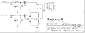
The PWM technique produces OK audio, but not good, clean audio. The software performs RPDF dithering and noise shaping to improve quality. Later RPi models (like the B+ and generation 2) have better power regulation and produce less digital noise at the audio output. There is much on-line debate about further improvements, but the PWM technique seems is limited by the 11-bit quantization. (This latter point alone is subject to debate!)
JACK seems to modify the audio sample stream as well. I can hear a loud hiss from my speakers when JACK is running and sending audio through the built-in DAC circuit. Ideally, the speaker should be completely silent.
Raspberry Pi 2 does not have an audio input. Thud!
Alternatives to built-in audio
If you want better audio quality or need to record an external audio signal, there are two approaches:
- Buy and install an audio board.
- Buy and install a USB audio interface.
With respect to the first approach, I briefly explored two of the available Raspberry Pi add-on audio boards:
- Cirrus Logic Audio Card
- HiFiBerry DAC Pro+
The Cirrus Logic board is well-specified with a WM5102 audio hub, WM8804 S/PDIF transceiver, and two WM7220 digital microphone integrated circuits. Those in the know will recognize these parts as Wolfson designs. The HiFiBerry DAC+ Pro is output only and uses an equally well-respected Burr Brown digital-to-audio converter (DAC).
Potential users are advised to be careful and to check compatibility with their particular model of Raspberry Pi. Adafruit cautions that the Cirrus Logic board may not be compatible with Raspberry Pi 2.
Both boards have drivers. However, both vendors eshew device configuration and prefer to distribute full OS images that include the requisite drivers. This approach puts existing users at a disadvantage. Now that I have Raspbian JESSIE installed and running, I would like to build and install the driver by itself, not write another micro SD card and go through the bring up process again.
With these issues in mind, I decided to go the USB audio interface route. It’s also the lowest cost option for me because I already have a Behringer USB audio interface in hand.
Behringer UCA-202 audio interface
The Behringer UCA-202 is an inexpensive ($30 USD) USB audio input/output interface. Analog signals are transfered on RCA connectors (left/right IN and left/right OUT). The UCA-202 also has a headphone output and an S/PDIF optical output. The UCA-202 is bus-powered and class-compliant. Conversion is 16-bit at 32kHz, 44.1kHz or 48kHz. The UCA-202 has a sister, the UCA-222, with the same spec.
I have used the UCA-202 as a plug-and-play audio interface with both Windows and Mac OS X. Now, I can claim success with Raspbian JESSIE Linux, too. This thing is the “pocket knife” of low-cost USB audio interfaces.
Even though I’m using a Behringer UCA-202, the directions below should also apply to other class-compliant USB audio interfaces. It never hurts to search the Web for directions, problems and tips for your particular audio interface. Just sayin’.
Before plugging in the UCA-202, run aplay -l and aplay -L to see a list of the sound cards (-l) and PCMs (-L) that are installed on your machine.
Next, plug the UCA-202 into one of the USB ports. Run the aplay commands, again, and look for a new audio device. On my machine, a new sound card appears in the aplay -l output:
    card 1: CODEC [USB Audio CODEC], device 0: USB Audio [USB Audio]
      Subdevices: 1/1
      Subdevice #0: subdevice #0
The new sound card is named “CODEC”, it is ALSA card number 1, and it has one subdevice (number 0). The aplay -L output lists a whole slew of new PCMs:
    sysdefault:CARD=CODEC
        USB Audio CODEC, USB Audio
        Default Audio Device
    front:CARD=CODEC,DEV=0
        USB Audio CODEC, USB Audio
        Front speakers
    surround21:CARD=CODEC,DEV=0
        USB Audio CODEC, USB Audio
        2.1 Surround output to Front and Subwoofer speakers
    surround40:CARD=CODEC,DEV=0
        USB Audio CODEC, USB Audio
        4.0 Surround output to Front and Rear speakers
    surround41:CARD=CODEC,DEV=0
        USB Audio CODEC, USB Audio
        4.1 Surround output to Front, Rear and Subwoofer speakers
    surround50:CARD=CODEC,DEV=0
        USB Audio CODEC, USB Audio
        5.0 Surround output to Front, Center and Rear speakers
    surround51:CARD=CODEC,DEV=0
        USB Audio CODEC, USB Audio
        5.1 Surround output to Front, Center, Rear and Subwoofer speakers
    surround71:CARD=CODEC,DEV=0
        USB Audio CODEC, USB Audio
        7.1 Surround output to Front, Center, Side, Rear and Woofer speakers
    iec958:CARD=CODEC,DEV=0
        USB Audio CODEC, USB Audio
        IEC958 (S/PDIF) Digital Audio Output
    dmix:CARD=CODEC,DEV=0
        USB Audio CODEC, USB Audio
        Direct sample mixing device
    dsnoop:CARD=CODEC,DEV=0
        USB Audio CODEC, USB Audio
        Direct sample snooping device
    hw:CARD=CODEC,DEV=0
        USB Audio CODEC, USB Audio
        Direct hardware device without any conversions
    plughw:CARD=CODEC,DEV=0
        USB Audio CODEC, USB Audio
        Hardware device with all software conversions
Not all of these PCMs are defined and configured by the way. Take note of the PCM named “hw:CARD=CODEC,DEV=0”. This is essentially the raw interface to the UCA-202. This PCM, at the very least, is defined.
Connect the audio outputs of the UCA-202 to powered monitors. Test the audio output interface by playing an audio (WAV) file:
aplay -D hw:1,0 HoldingBackTheYearsDb.wav
or:
aplay -D hw:CARD=ALSA,DEV=0 HoldingBackTheYearsDb.wav
Please note that you need to pass in the entire PCM name “hw:CARD=CODEC,DEV=0“.
Connect an audio source to the inputs of the UCA-202. Test the audio input interface by recording to an audio (WAV) file:
arecord -D hw:CARD=ALSA,DEV=0 -f cd test.wav
I had trouble with the duration (-d) option. YMMV. Type Control-C to stop recording. Then, play back the test audio file through the UCA-202.
That’s all there is to it! The UCA-202 is truly plug and play.
Configure JACK and other applications
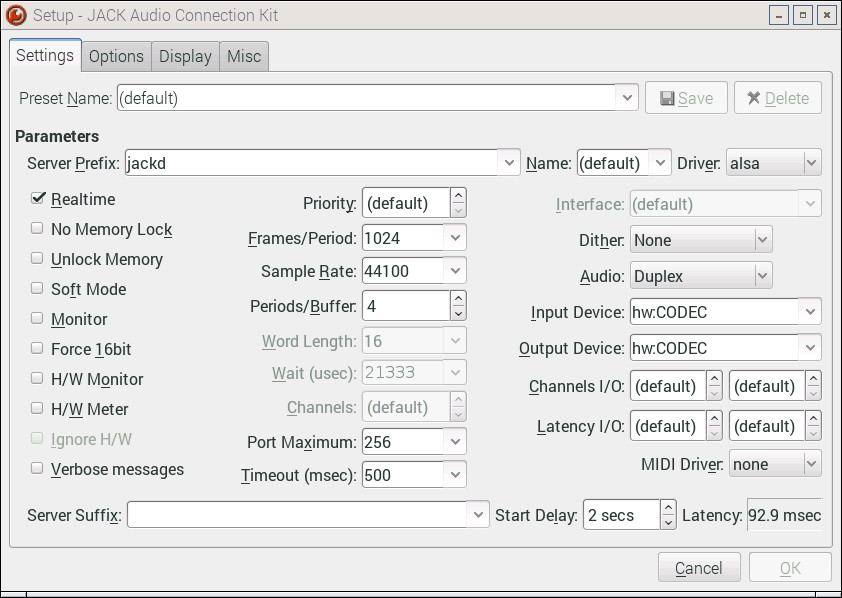
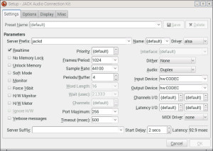
You need to tell the JACK audio server to use the UCA-202 instead of the RPi’s built-in audio device. Run qjackctl and click the Settings button. Select “hw:CODEC” as the Input Device and Output Device. (See the image below.) Click OK to return to the main control panel and start the JACK server. The server routes digital audio to and from the UCA-202 and JACK clients. Launch amsynth and click its Audition button. You should hear sound from the powered monitors that are connected to the UCA-202.
ALSA’s aplay and arecord commands are OK for testing, but are clunky for practical use. Let’s install Audacity:
sudo apt-get install audacity
Audacity is the well-known cross-platform, open source, audio editing tool.
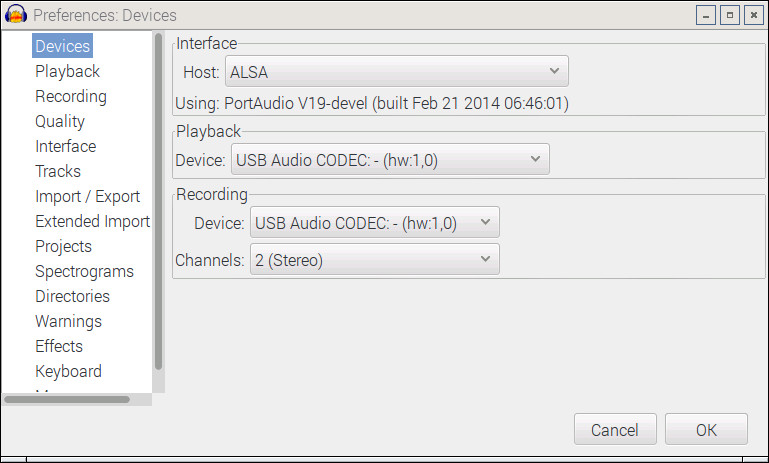
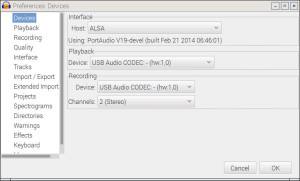
Edit Audacity’s preferences to set the audio interface. (See the following image.) If you want to use ALSA directly, set the interface Host to ALSA. Then set the Playback and Recording Devices to “USB Audio CODEC”. Audacity should now be able to play and record through the UCA-202.
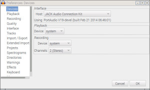
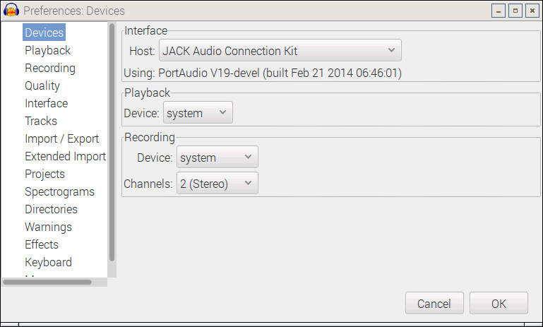
If you prefer to use JACK instead, once again edit Audacity’s preferences. (See the following image.) Set the interface Host to “JACK Audio Connection Kit”. Set the Playback and Recording Device to “system”. Make sure the JACK audio server is running. You may need to restart Audacity at this point. Play back an audio file or try recording a new file. JACK should serve the UCA-202 audio to/from Audacity.