Connect a MIDI shield to littleBits Arduino

My do-it-yourself MIDI interface for littleBits Arduino probably isn’t for everyone. Constructing the DIY interface requires circuit layout skills and not everyone wants to whip up a board from scratch and a schematic.

Fortunately, there are a couple of alternatives: the Olimex SHIELD-MIDI and the Sparkfun MIDI Shield. I don’t have any direct experience with the Olimex, but I have built and used the Sparkfun MIDI Shield (Sparkfun product number DEV-12898) and the now retired MIDI Breakout Board. The Olimex SHIELD-MIDI is very similar to the retired breakout board. In this post, I show how to hookup the Sparkfun MIDI Breakout Board to the littleBits Arduino. The wiring is the same for the Sparkfun MIDI Shield. That’s the neat thing about the standard Arduino form factor.

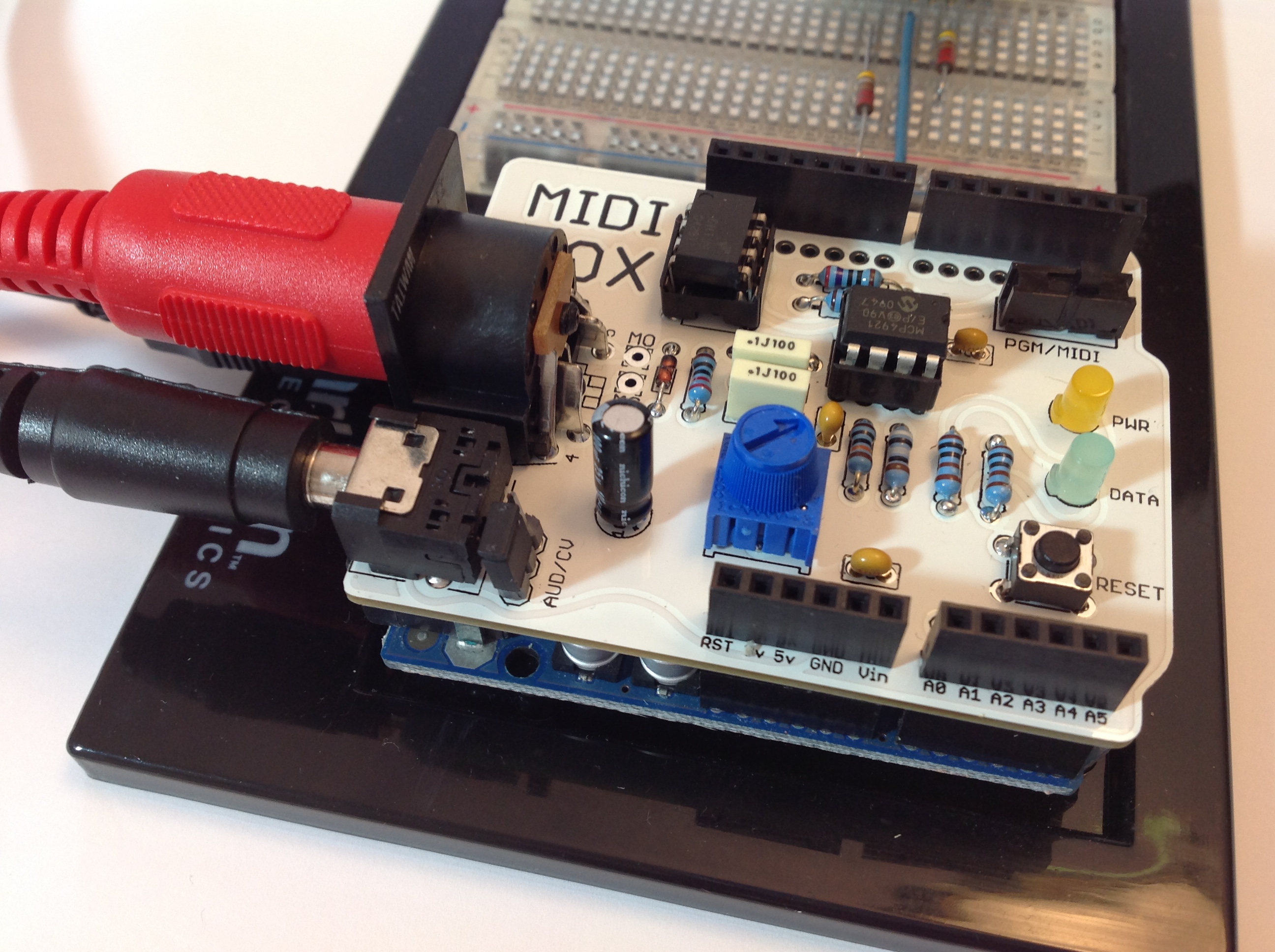
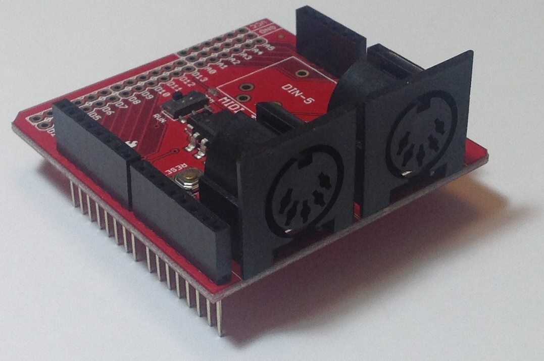
I would demonstrate with a Sparkfun MIDI Shield, but all of my MIDI Shields are customized in some way! The Sparkfun MIDI Breakout Board is basically the same as the MIDI Shield except that it doesn’t have the potentiometers and tactile switches. The image below is a picture of the Sparkfun MIDI Breakout board. (Click on the image to get higher resolution.) The two 5-pin DIN connectors are the MIDI IN and MIDI OUT ports. The long pins extending below the breakout board plug into a standard Arduino like an UNO or Leonardo.

sparkfun_midi_breakout

The Sparkfun MIDI breakout board (or shield) arrives as a kit, so you still need to do some assembly. Sparkfun has already installed and soldered the tough stuff like the optoisolator, resistors and so forth. The MIDI Shield is a good beginner’s kit because the components to be installed are large and easy to solder. If you skip installing the potentiometers and tactile switches, the job is even easier!

You might want to add an Arduino Stackable Header Kit (PRT-10007), however. With the header kit, you’ll be able to interconnect using standard jumper wires. Once the headers are installed, no further soldering is necessary. Just plug the jumpers into the headers and play. Mistakes are easier to correct with jumper wires, too.

Here is the top-view of the MIDI breakout board, an Arduino UNO processor board and a Sparkfun MIDI Shield. Click the image for higher resolution. You’ll want to take a closer look at the three boards in order to see the signal name associated with each header pin. (You can really zoom in if you download the image and load it into a paint program.)

midi_bob_uno_shield

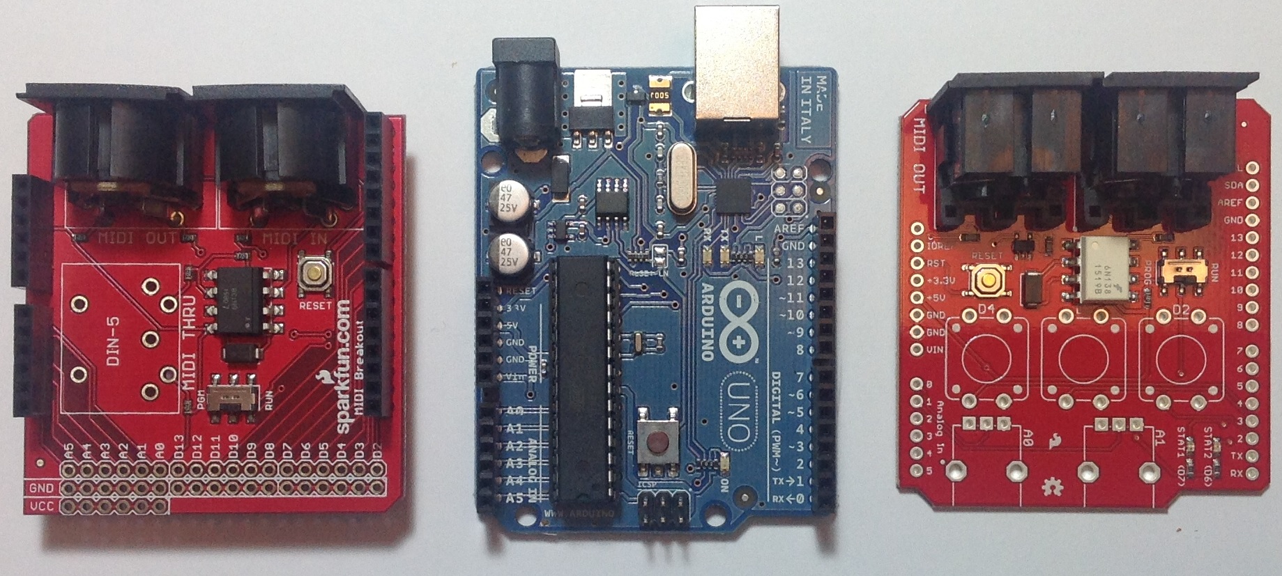
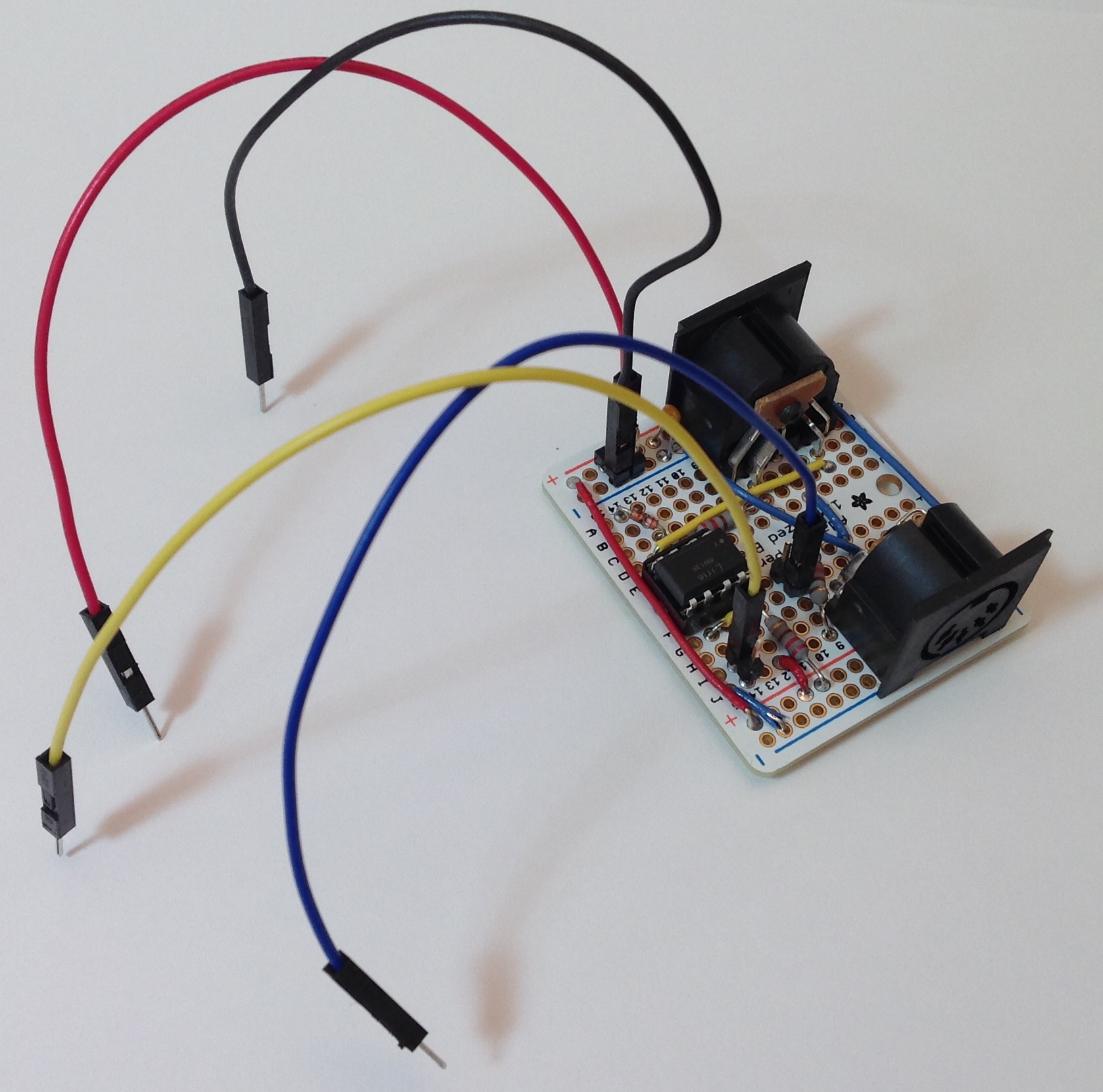
The breakout board has a position for a MIDI THRU connector. This position is empty as the headers would block the opening of the 5-pin DIN connector. We don’t need the THRU port, so this isn’t a deal-breaker.

As I mentioned before, the long pins extending below the headers normally plug into a standard Arduino processor board (e.g., UNO or Leonardo). Each header pin effectively mirrors the electrical signals of the underlying Arduino board. So, in order to hookup to the littleBits Arduino, we just need to connect the appropriate Arduino board signals to the corresponding bitSnaps on the littleBits Arduino. That’s why you really want to zoom in and see the signal names. The board labels tell us where to plug in jumper wires.

We need four connections:
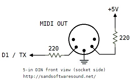
  • +5 Volts: Red wire
  • Ground: Black wire
  • RX (digital pin D0): Yellow wire
  • TX (digital pin D1): Blue wire

Our old high school shop teacher would yell at us if we didn’t use the right color wire for power, ground, etc. I will say, different wire colors make it easier to check and debug wiring!

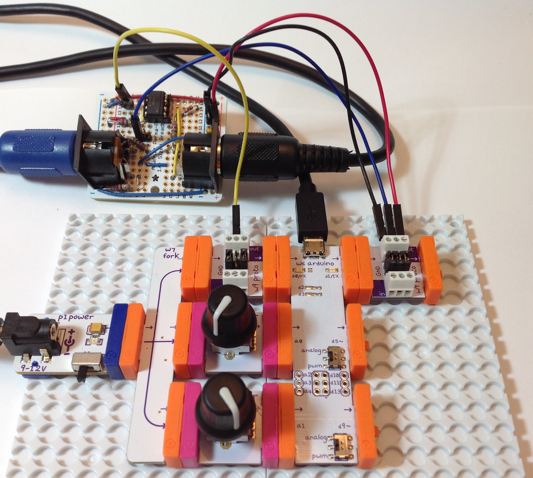
So, how do we make connections to the littleBits Arduino? I used two littleBits proto modules: one proto module for the MIDI input side and one proto module for the MIDI output side. The other end of each jumper terminates in a screw connector on a proto module. Please see the image below. (Click to enlarge.)

sparkfun_midi_littlebits_arduino

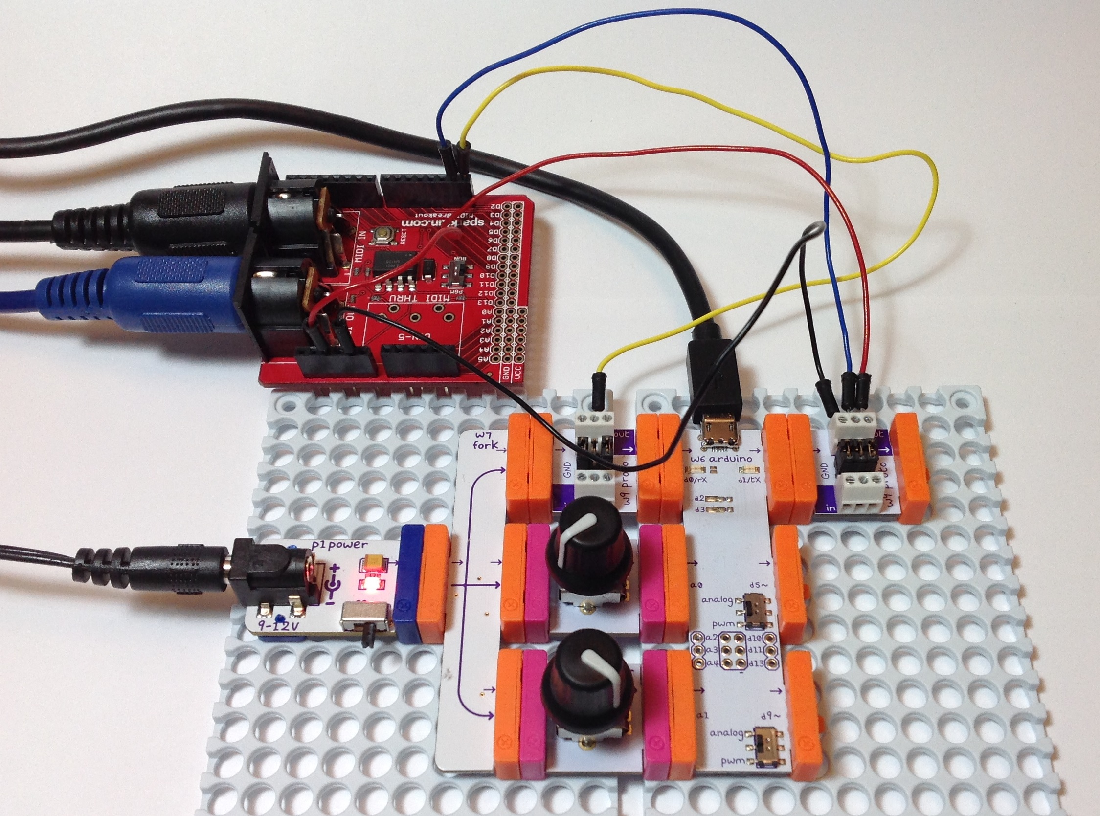
RX is connected to RX, TX to TX, +5 Volts to +5 Volts, and Ground to Ground. The MIDI IN goes to the Arduino’s RX pin and the the Arduino’s TX pin goes to MIDI OUT.

You must configure the jumpers on each proto module. The MIDI OUT side is easy; just leave all three jumpers installed. One the MIDI IN side, remove the center jumper on the proto module. This breaks the connection from the proto board input to the proto board output. You must remove this jumper or the input signal will interfere with the incoming MIDI data.

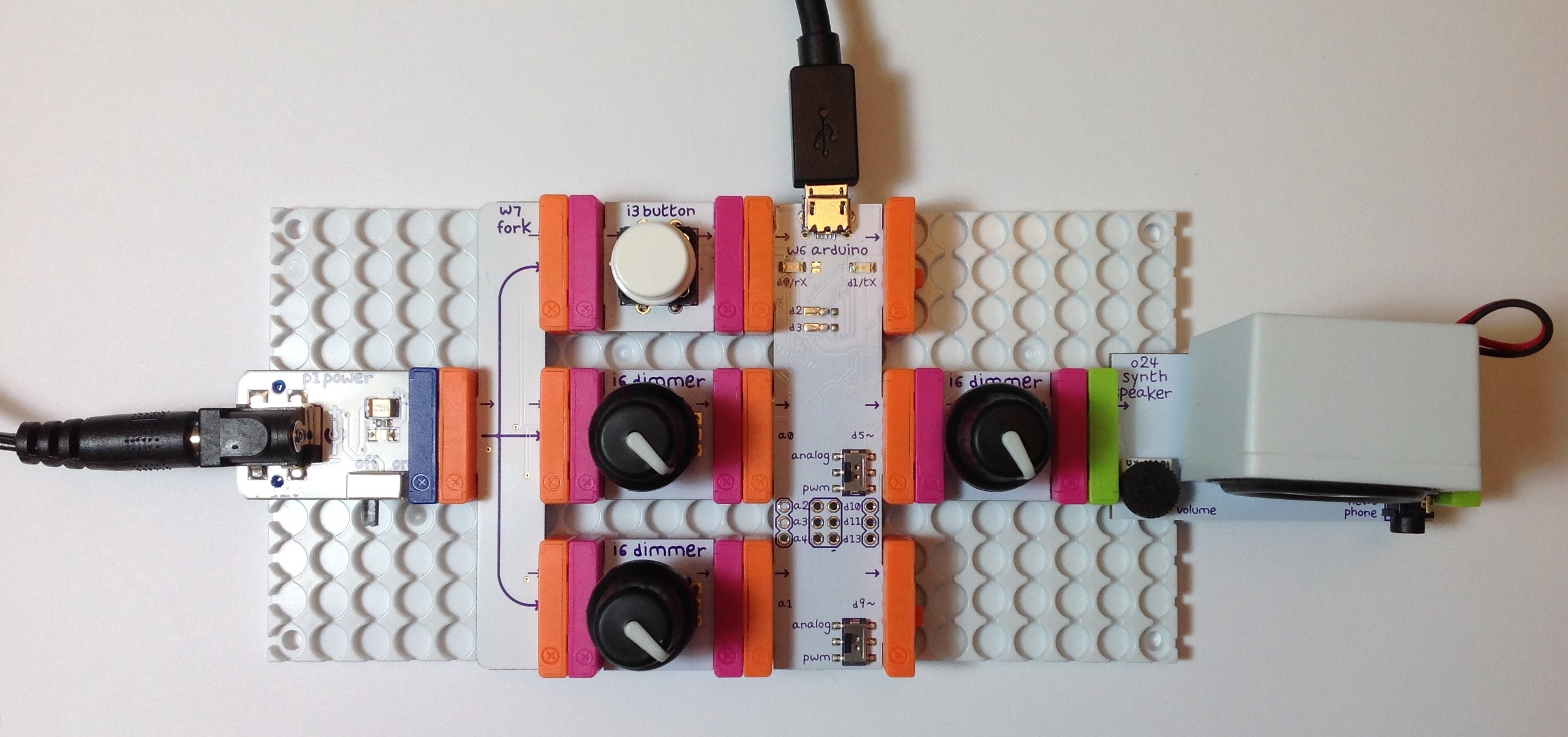
Once all of the connections are made, you’ll need sketches to test the connections. Please see my article about testing an Arduino MIDI interface. The article describes a simple testing process. The article also has links to a simple MIDI sequencer sketch and the source code for a MIDI IN to MIDI OUT sketch. The MIDI sequencer sketch checks the MIDI OUT side. Once you know the MIDI OUT is good, then the MIDI IN to MIDI OUT sketch checks the MIDI IN side. (The sketch echoes MIDI IN to MIDI OUT.)

That’s it! You should now have your 5-pin MIDI equipment talking with the littleBits Arduino. If this project has bolstered your confidence with hardware — and I hope that it has — then please take a look at the DIY 5-pin MIDI interface project.

littleBits Arduino MIDI interface

I thought, “When it comes time to test the 5-pin MIDI interface with the littleBits Arduino, just hook it up. Download the sketches. Take a victory lap.”

Instead, I got an “opportunity” to discover and learn. Not so fast, but not so bad, either.

Please recall that a few posts ago I described the design of a 5-pin MIDI interface for Arduino. The MIDI IN part of the interface attaches to the Arduino RX pin (pin D0) and the MIDI OUT part connects to the TX pin (pin D1). I tested the 5-pin MIDI interface with an Arduino UNO board using the simple MIDI sequencer sketch and a sketch to echo MIDI IN to MIDI OUT. My original plan was to connect the 5-pin MIDI interface to the littleBits Arduino via two protoboards, then run the sketches, again, for testing.

First, the hook up. The image below shows the littleBits hardware. (Click the image for full resolution.) The Arduino is “at the heart” and communicates with a PC through the USB port. The littleBits proto module directly to the left of the USB port brings the logic-level MIDI IN signal to the Arduino RX pin. The proto module directly to the right of the USB port sends the Arduino TX signal to the MIDI OUT circuit. The signals to and from the 5-pin MIDI interface board are:

  • Yellow wire: Logic-level MIDI IN
  • Blue wire: Logic-level MIDI OUT
  • Red wire: +5 Volts (Vcc)
  • Black wire: Ground

MIDI is a serial communication standard operating at a rate of 31,250 bits per second. RX and TX are the Arduino’s digital serial receive and transmit pins, respectively.

littlebits_arduino_midi_interface

So far, so good. There are a few extra details to consider. The positive supply voltage (+5 Volts) and ground are distributed throughout the whole interface board. Only one set of power supply connections are needed to power the interface board. I attached the power supply connections to the proto module handing the MIDI OUT. Next, the proto module jumpers are configured a little bit differently on the MIDI IN and MIDI OUT sides. Having all three jumpers in place, the MIDI OUT proto module passes all signals: Vcc, ground and the data signal arriving from TX. The MIDI IN proto module only passes Vcc and ground. It does not pass the signal from its input bitSnap. The output from the proto module is generated by the signal coming from the 5-pin MIDI interface board (i.e., the yellow wire). This signal is send to the RX pin.

Adhering to my original test plan, I downloaded the simple MIDI sequencer sketch. This sketch tests the MIDI OUT circuit by sending MIDI note on and note off messages. I attached the MIDI OUT connector to a MIDI tone module, flipped the power switch, and no sound. MIDI data was not being sent to the MIDI tone module. After much wailing, gnashing of teeth and browsing, I remembered that the Arduino Leonardo board has two serial ports, not one port like the UNO. One serial interface handles RX/TX and another serial interface handles USB communications.

The littleBits Arduino is a Leonardo board. Was the MIDI data being sent to the USB port? I turned on the Serial Monitor in the IDE. Yep, the Serial Monitor was showing jibberish arriving from the Arduino. I expected jibberish because the bit rate was all wrong, but nonetheless, observations confirmed that MIDI data was going to the wrong port (USB instead of TX).

The Arduino IDE exposes two serial ports for a Leonardo board:

  • Serial” refers to the virtual serial port over USB.
  • Serial1” refers to the serial port through RX/TX.

Originally, I wrote and compiled the MIDI sequencer sketch for an Arduino UNO board. The calls to write() refered to Serial. That’s fine on the UNO because the UNO uses the same serial port for RX/TX and USB communication and everything works. On Leonardo (littleBits), however, the sketch refers to the USB serial port, not RX/TX as I had intended.

I solved the problem with conditional compilation. Here is the new code for the function MidiSend() in the MIDI sequencer sketch:

//
// Send a short, 3-byte MIDI message
//
void MidiSend(byte cmd, byte data1, byte data2)
{
#ifdef LEONARDO
  Serial1.write(cmd | CHANNEL) ;
  Serial1.write(data1) ; 
  Serial1.write(data2) ; 
#else
  Serial.write(cmd | CHANNEL) ;
  Serial.write(data1) ; 
  Serial.write(data2) ; 
#endif
}

The symbol “LEONARDO” determines the code to be compiled into the sketch. If LEONARDO is defined then the sketch sends MIDI bytes to Serial1. If LEONARDO is not defined, then the sketch sends MIDI bytes to Serial. I also needed to fix up the code in setup():

#ifdef LEONARDO
  Serial1.begin(31250) ;
#else
  Serial.begin(31250) ;
#endif

After making these changes and defining LEONARDO at the beginning of the sketch:

#define LEONARDO 1

I compiled and uploaded the sketch. Voila! I heard music from the tone module! MIDI data was now being sent to the appropriate Arduino serial port (TX).

Along the way, I also learned some useful information about the RX and TX LEDs. The RX and TX LEDs flash when data is transfered through the USB port. They do not flash when data is sent through the RX/TX pins. If you want to flash the LEDs yourself, then use the following macros:

    RXLED0;
    RXLED1;
    TXLED0;
    TXLED1;

These macros are a feature of the Leonard board and are not recognized on UNO.

Two separate, independent serial ports has its advantages. First, it isn’t necessary to disconnect the 5-pin MIDI interface board when uploading a sketch. With only one serial port on UNO, TX/RX and USB communication cannot peacefully co-exist. On Leonardo (littleBits), they do peacefully co-exist and you can use the virtual serial port over USB (i.e., Serial Monitor) to trace program execution and print debug messages while using RX/TX for MIDI communication. Finally, if we don’t ever touch Serial1, we should be able to configure D0 and D1 as regular Arduino digital input and output pins (respectively).

By now, you realize that I had to modify the sketch that echoes MIDI IN to MIDI OUT, too. Instead of conditional compilation, this sketches defines a symbolic constant, “SERIALPORT,” which expands to the name of the serial port to be read and written. Full disclosure: I did not test the MIDI library version on littleBits (Leonardo).

//
// Send MIDI IN to MIDI OUT (THRU)
//

// Author:  P.J. Drongowski
// Date:    6 June 2016
// Version: 1.1
//
// Copyright (c) 2016 Paul J. Drongowski
// Permission granted to use, copy and distribute

// Uncomment the following line to use the Arduino 
// MIDI library instead of serial read() and Write().
// #define USE_MIDI_LIBRARY 1
// This has not been tested/debugged on LEONARDO!

// Define the symbol SERIALPORT to select the appropriate
// serial port:
//    Serial    UNO
//    Serial1   LEONARDO/littleBits
#define SERIALPORT Serial1


#ifdef USE_MIDI_LIBRARY

#include <MIDI.h>
MIDI_CREATE_DEFAULT_INSTANCE() ;

void setup() {
  MIDI.begin(MIDI_CHANNEL_OMNI) ;
}

void loop() {
  if (MIDI.read())
  {
    MIDI.send(MIDI.getType(),
              MIDI.getData1(),
              MIDI.getData2(),
              MIDI.getChannel());
  }
}

#else

int midiByte = 0 ;

void setup() {
  // Initialize the serial port for MIDI
  SERIALPORT.begin(31250) ;
}

void loop() {
  if (SERIALPORT.available() > 0) {
    midiByte = SERIALPORT.read() ;
    SERIALPORT.write(midiByte) ;
  }
}
#endif

MIDI sequencer: Testing your MIDI interface

Now that you’ve assembled the MIDI interface for your Arduino, it’s time to try it out. That means you need a few basic sketches to test and debug the interface.

First, a philosophical word or two. Testing is one of the most neglected and least emphasized topics in engineering. Other than careful design, assembly and coding, nothing else is as important to the success of a project as testing. In practice, you should be thinking about testing while you design, code, layout and solder. Without getting too computer science-y, it all comes down to controllability and observability — the ability to apply a stimulus (test input) and the ability to measure and assess a response (expected vs. actual test output).

Take the case of our MIDI interface. There are two major subsystems: the MIDI IN circuit and the MIDI OUT circuit. We must drive the MIDI IN circuit with a keyboard (or some other device) that sends MIDI to the 5-pin MIDI IN connector. The Arduino reads the logic level bit-stream through its RX pin (pin D0). The messages in the bit-stream need to conform to the MIDI message standard. On the MIDI OUT side, the Arduino sends a logic level bit-stream into the MIDI OUT circuit via the TX pin (pin D1). Again, the bit-stream carries standard MIDI messages. We must observe the outgoing MIDI messages, perhaps by playing the MIDI stream into a MIDI-compatible keyboard or tone module.

In addition to controllability and observability, you also need a test plan that identifies the features to be tested and the order in which you intend to test those features. A carefully constructed plan can make your work more efficient and systematic. Again, taking the case of the MIDI interface, I intend to test the MIDI OUT side first because I can easily write a sketch to generate MIDI messages and that sketch does not require a working MIDI IN circuit. Once I know that the MIDI OUT is correct, I can use the MIDI OUT as part of MIDI IN testing. By testing MIDI OUT first, I can work around the limited controlability and observability of our system.

I hope this plan makes sense to you. Here’s a few additional points. We don’t need to test all MIDI standard messages and can restrict testing to simple 3-byte messages like NOTE ON and NOTE OFF. We need to have a reliable, known-good MIDI sender (like a keyboard or other controller) and MIDI receiver (like a tone module). I have two MIDI-compatible devices — a Roland SK-88 Pro Sound Canvas keyboard and a Boss DS-330 Dr. Synth module — that I like to use for testing. Both devices now have emeritus status, meaning that I won’t cry too much if I blow them up! I send the MIDI OUT from the Arduino to both devices and play the audio through self-powered speakers. I play the SK-88 keyboard and send MIDI NOTE ON and NOTE OFF messages to the MIDI IN circuit under test and read those messages on the Arduino.

With these preliminaries out of the way, let’s dive into the details.

MIDI OUT: Simple MIDI Sequencer

In order to test MIDI OUT, we need a sketch that sends MIDI NOTE ON and NOTE OFF messages via the TX pin into the MIDI OUT circuit. With a MIDI tone generator connected to the 5-pin MIDI OUT connector, we just need to listen to the audio from the tone generator to determine if the outgoing notes are correct.

I took the simple Arduino tone sequencer sketch and modified it to send MIDI NOTE ON and NOTE OFF messages. I replaced calls to the Arduino tone() function with code to send MIDI NOTE ON and NOTE OFF as appropriate. (Reusing code this way is known as “copy and modify.”) The new sketch is a simple MIDI sequencer that repeatedly plays back a musical sequence of notes through the MIDI OUT port. The sketch is a useful little program in itself — not just a specialized test.

Here are direct links to the source code for the sketch:

MidiNoteNum.h: Defines symbolic constants for the note names
ToneNote.h: Defines symbolic constands for note/rest durations
MidiSeq.ino: The simple MIDI sequencer Arduino sketch

The sketch does not use the Arduino MIDI library. It sends messages by making calls to the Arduino Serial library. I will use the Arduino MIDI library in future projects, especially when we need to parse complicated incoming messages.

The sketch sends messages on MIDI channel 1. So, be sure to have the destination tone generator configured to receive on channel 1 (or OMNI).

Here’s a possible gotcha that could drive you insane. The Arduino’s serial port is used for both uploading sketches and for MIDI communications. MIDI operates at a rather “unusual” data rate of 31,250 bits per second and most likely does not match the default rate established by the Arduino IDE. Even worse, the MIDI devices used for testing (i.e., keyboard controller) may be sending real time status messages that collide with commands from the IDE. Soooo, you may see messages about “sync” failure when uploading a sketch. If that is the case, then temporarily disconnect the MIDI IN circuit while uploading a sketch. Also, you will not be able to print to the serial port, etc. and see text serial messages in the IDE’s Serial Monitor window. Unfortunately, this limits the use of serial communication for tracing and debugging purposes when MIDI is connected and active.

MIDI IN: Echo MIDI IN to MIDI OUT

Once we know that the MIDI OUT port is working, it’s time to check the MIDI IN port. An easy way to test is to simply echo the incoming MIDI messages to the MIDI OUT port. If we have a MIDI keyboard connected to MIDI IN and a tone generator connected to MIDI OUT, then anything that we play on the keyboard should be heard through the tone generator. If the keyboard and tone generator are part of the same instrument (e.g., a synthesizer workstation, arranger or digital piano), be sure to turn LOCAL off. You want to hear the MIDI messages coming in through the instrument’s MIDI IN port.

Here is the code for the MIDI IN to MIDI OUT sketch.

//
// Send MIDI IN to MIDI OUT (THRU)
//

// Author:  P.J. Drongowski
// Date:    30 May 2016
// Version: 1.0
//
// Copyright (c) 2016 Paul J. Drongowski
// Permission granted to use, copy and distribute

// Uncomment the following line to use the Arduino 
// MIDI library instead of serial read() and Write().
// #define USE_MIDI_LIBRARY 1

#ifdef USE_MIDI_LIBRARY

#include <MIDI.h>
MIDI_CREATE_DEFAULT_INSTANCE() ;

void setup() {
  MIDI.begin(MIDI_CHANNEL_OMNI) ;
}

void loop() {
  if (MIDI.read())
  {
    MIDI.send(MIDI.getType(),
              MIDI.getData1(),
              MIDI.getData2(),
              MIDI.getChannel());
  }
}

#else

int midiByte = 0 ;

void setup() {
  // Initialize the serial port for MIDI
  Serial.begin(32500) ;
}

void loop() {
  if (Serial.available() > 0) {
    midiByte = Serial.read() ;
    Serial.write(midiByte) ;
  }
}
#endif

There are two ways to echo the incoming MIDI message stream. One way is to echo the bytes arriving on the serial input to the serial output. This is the most straightforward method. The other way is to use the Arduino MIDI library to read incoming MIDI messages and send the messages to the MIDI OUT port. The code (above) implements both methods and uses conditional compilation (#ifdef) to select and compile one of the methods. If you want to get your feet wet with the Arduino MIDI library, then define the symbol USE_MIDI_LIBRARY before the #ifdef.

Here are a few links for the Arduino MIDI library to help you get started.

Arduino MIDI Library site
Arduino MIDI Library Documentation
Deprecated site

The current version is 4.2. The Arduino IDE has a nice library management system: Sketch > Include Libraries > Manage Libraries.

5-pin MIDI IN/OUT for Arduino

I hope you enjoyed the last post about a simple tone-based sequencer for littleBits Arduino. My next goal is to make the littleBits Arduino fluent in MIDI. Then we can turn the littleBits Arduino into the heart of MIDI-based tools like real time controllers and synthesizers.

At the time of this writing, littleBits does not offer a 5-pin MIDI input module or a 5-pin MIDI output module. That shouldn’t stop us. With a little know-how and some soldering, it’s easy to whip up 5-pin MIDI IN and MIDI OUT circuits. I will show you how. Even though this discussion is in the context of littleBits Arduino, the circuits below will work with any Arduino. The circuits will even work with Raspberry Pi or Beaglebone for that matter! Once I get a couple littleBits proto modules, I’ll show you how to connect the MIDI interface circuits to the littleBits Arduino.

5-pin MIDI is a mature standard and is one of the most successful, long-running standards in personal computing. Most musicians are familier with MIDI cables and MIDI connections. MIDI cables have familiar 5-pin DIN connectors at either end. Wiring is symmetric. Unlike USB, there isn’t an A side and a B side. Connect a MIDI OUT to a MIDI IN and you’re good to go.

Even though a connector has five pins (and associated wires), only three pins are really involved in MIDI data communication. One of the three pins — “the one in the middle” — carries electrical ground. The other two pins form a current loop from the sender to the receiver and back to the sender. “Current loop” means that we are communicating 0’s and 1’s using the presence or absence of electrical current.

Everyday logic like CMOS or TTL digital circuits use voltage level to represent logical zero and logical one. Low voltage (nominally 0 Volts) represents logical zero and high voltage (nominally 5 Volts in a 5 Volt system) represents logical one. Digital circuits actually switch through a transition zone between 0 and 5 Volts. Logical 0 and 1 are defined by threshold voltages, and now we’re getting too far afield! You get the idea — the representations and electrical mode of operation are different.

Let’s start with the receiver (MIDI IN) because that’s where all of the interesting action takes place. Here is the schematic for a very basic MIDI IN. (Click on images to get full resolution.)

schematic_midi_in

The incoming current flows through a 220 ohm resistor into the optical side of a 6N138 optoisolator. That may sound scary, but Arduino folks already know how to blink an LED on and off. That’s what the current loop does. It blinks an LED in the optoisolator. The LED shines on a photodiode that controls two transistor switches. The transistors switch the output (pin 6 of the optoisolator) between logical 0 and logical 1 (in voltage-ese). Pin 6 is connected to the Arduino serial receive port (pin D0, also known as “RX”). That’s all there is to it!

The optoisolator isolates the sender and receiver electrically. This is a good thing in stage environments and any place rife with grounding problems, connection mistakes, etc. The resistor before the LED limits the current through the loop and into the LED. This resistor plus the 1N4148 diode provide input protection.

Here is the schematic for a basic MIDI OUT circuit.

schematic_midi_out

All the sender needs to do is to drive or remove an electrical current through the loop. When the loop is driven, the LED at the other end of the loop shines. When the current is removed, the LED turns off. The current loop is controlled by the Arduino send port (pin D1, also known as “TX”). The 220 ohm resistors are current limiting resistors that put a limit on the amount of current driven into the loop.

This MIDI OUT circuit gets the job, but is a little basic. Most practical commercial circuits use a driver (such as a CMOS 74HC125 buffer/driver IC) or a transistor switch. The driver provides a little more electrical assurance and protection on the sender’s side. Better to blow up an inexpensive driver IC than your Arduino!

I built both the MIDI IN and MIDI OUT circuits on an Adafruit Perma-Proto quarter-sized breadboard PCB. I like the layout of these boards and they have nice through-holes for soldering. They have the same layout as a quarter-sized solderless breadboard. In this case, you solder connections instead of inserting jumper wires and component leads into solderless breadboard holes. Please, note. If you want to use the circuits above, but are reluctant to solder, then by all means, use a solderless breadboard!

The following image shows the final result looking at the MIDI IN connector. Click the image for full resolution.

board_midi_in

The jumper wires sprouting from the board are not intended to make the board look like a court-jester. They are the connections to be made to the Arduino:

  • Red: +5 Volts
  • Black: Ground
  • Yellow: Connect to D0 / RX
  • Blue: Connect to D1 / TX

My construction style uses 2×1 and 2×2 headers to make external connections. The header pins mate up neatly with either Female/Female or Female/Male jumper wires. I used F/M jumpers in order to plug into the signal headers on a standard Arduino UNO for testing.

The next image shows the final resulting looking at the MIDI OUT connector.

board_midi_out

If you don’t mind soldering, but don’t want to go free-style on a prototyping board, then I recommend the Sparkfun MIDI Shield (DEV-12898). The latest revision of the MIDI Shield has good input protection and output drivers. It also has a RUN/PROG switch that is handy when uploading a sketch to the Arduino. MIDI and PC communications share the same serial port and conflicts must be avoided. (More about this issue in another post.) With the prototyping board, I just pull the yellow jumper wire when I upload a sketch.

The Sparkfun MIDI Shield has two knobs and three switches. This is a bonus if you are working with a standard Arduino. The knobs and switches go unused if you are working with a littleBits Arduino. In either case, the Sparkfun MIDI Shield is a viable alternative to “roll you own.”

Next time, I’ll describe the sketches that I wrote in order to test the MIDI IN and MIDI OUT.

Update: Use this simple MIDI sequencer sketch to test the MIDI OUT portion of the 5-pin interface.

littleBits Arduino tone sequencer

The littleBits Arduino module has the potential to be a MIDI-driven tone generator for a mono or paraphonic synthesizer. After getting the module, I was anxious to try it out even though I haven’t built a MIDI interface for it (yet).

Here is a picture of the littleBits hardware. (Click the image to get full resolution.) The Arduino module is in the middle between the controls at the left (button and dimmers) and the synth speaker at the right. The controls on the left hand side don’t do anything at the moment. I put a dimmer between the output pin (D5) and the synth speaker in order to control audio volume. It’s just more convenient to control the volume with a dimmer than the tiny trim pot on the synth speaker module. The knobs on the dimmers are my own touch; they aren’t standard-issue with the littleBits dimmers.

arduino_dimmer_speaker

To keep things simple, I wrote a sketch that implements a basic note sequencer. Each note has a pitch (frequency) and a duration (milliseconds). The notes are stored in an array. The Arduino loop() function steps through the array of notes and plays one note at a time. After the loop plays the last note in the array, it goes back to the beginning of the array. The loop has a delay() in it and the loop keeps track of the remaining duration of the currently playing note. The sketch calls the Arduino tone() function to play notes by sending a square wave at the desired frequency to output pin D5.

If you would like to learn more about this project, then read about the design of this simple Arduino-based sequencer and tone generator. Here are links to the source code:

ToneTest.ino: Main sketch
ToneFreq.h: Note frequencies
ToneNote.h: Note durations

The D5 and D9 output pins on the littleBits Arduino module have a switch that enables or disables low pass filtering. The “analog” switch position turns on the filtering. The “pwm” position turns filtering off. Should you build this project yourself, try both switch positions. The “pwm” position doesn’t filter the square wave and you will hear it loud and nasty. The “analog” position produces a quieter, mellower timbre thanks to the low pass filter. Be sure to try the littleBits synth filter, envelope and delay modules, too.

One more tidbit. Pictures of the littleBits envelope, filter and delay modules usually show the top-view. The picture below flips the modules over and shows the bottom-view.

envelope_filter_delay

From left to right, the modules are the envelope, filter and delay, respectively. There is some serious electronics on these boards! (Click the image for full resolution.) I hope to use these modules to mangle audio, not just synthesis.

All the best.

Update: 28 June 2016. If you enjoyed this project and have the littleBits Synth Kit, then check out an expanded version of the tone sequencer which drives the filter and envelope modules.

littleBits Arduino: More observations

Back with a few more quick observations as I get started with the littleBits Arduino module. (Please see my first review.)

I decided to see how much stuff I could cram around the littleBits Arduino. (Click on the image below for full resolution.) This configuration starts with the power module on the left hand side. The power module is connected to a 9V 1500mA (1.5A) center positive power adapter with a 2.1mm plug. As I mentioned in my previous post, this is the same adapter that I use with my Arduino UNO. Already, I like the power switch on the power module — a very handy touch.

arduino_full_up

The power module drives three input modules (a button and two dimmers) via the fork module which is included in the Arduino Development Kit. The button module is connected to Arduino digital input D1 and the dimmer modules are connected to the Arduino analog inputs A0 and A1.

The Arduino D5 output is connected to a dimmer module that adjusts the volume (amplitude) of the signal sent to the synth speaker module. Yep, the synth speaker module has a volume control of its own. It’s that little trim pot in the lower left corner of speaker module. I find it difficult to adjust the tiny trim pot. Trim pots are designed for “set and forget” applications and have a limited rotational life (number of cycles). So, I splurged and inserted a dimmer module on the input to the speaker module.

I love the bargraph. You can use it as a poor man’s volt meter or logic indicator. I connected the bargraph module to Arduino output D9. Before I forget, the switches for D5 and D9 are set to the “analog” position.

I didn’t connect anything to Arduino digital output D1. A good first sketch would be blinking the on-board D1 LED on and off. So, I left the bitSnap empty.

The knobs on the dimmer modules are my own doing. The knobs do not come with the dimmer modules. I have a dozen or so of these basic knobs. The equivalent knobs are:

  • Multicomp CR-BA-7C6-180D ($0.35 per knob through MCM Electronics)
  • Sparkfun COM-08828 (now retired)

Knobs just make life easier and make things a little more dressed up.

I was hoping that littleBits had preloaded a sketch to the Arduino module and they did. The preloaded sketch makes the bargraph “breathe.” The sketch repeatedly ramps up the output voltage from zero volts to the MAX (5 volts) and ramps the voltage back down to zero volts. The dimmer connected to A1 controls the ramping speed, i.e., how fast the bargraph breathes.

I wish that littleBits made the preloaded sketch available on their web site. I couldn’t find it. Quite frequently, it’s handy to have a known-good sketch for testing purposes. I’m a stickler for testing and diagnostic programs. Too much emphasis on coding, not enough emphasis on testing, I say.

The littleBits site has a good introduction to installing and using the Arduino Integrated Development Environment (IDE). If you’re confused about the “analog” and “pwm” switch settings, be sure to scroll down into the comments section on this page. There is a good explanation. A short bit of advice: If you need to send an analog signal that varies anywhere from 0 to 5 volts, then put the switch into the “analog” position. If you need to send a purely digital signal (ON: 5V, OFF: 0V), then put the switch in the “pwm” position. (A pulse chain is, of course, a type of digital signal.)

If you’ve taken a look at the Arduino module schematic, you know that the switch enables (or disables) two extra stages of low pass filtering. The low pass filters (when enabled) generate an analog signal by smoothing out a PWM signal. This is essentially a poor man’s digital to analog converter (DAC) although it isn’t very hi-fi.

The littleBits web site has ten sketches to get you started. This part of their site could use a little polishing. First, I couldn’t find the source code for the sketches! At last, I realized that the link to a sketch is under the “ADDITIONAL FILES” section on the right hand side of the page — beneath the relatively huge “ADD ALL TO CART” button. Ah, sales before service. Beginning users may not realize that this is the link to the code. They may not know that the “ino” file extension refers to an Arduino IDE code file! Maybe kids are less confused than adults, but details like this could easily turn off a youngster who is lacking self-confidence.

The sketch file names are a little whack and don’t always directly refer to the section or page titles on the sketch web pages. Here is a correspondence table that I put together:

Example                     Source code file
--------------------------  ------------------------------
Blink                       blink.ino
Hold An On/Off State        buttonRead_stateChange.ino
Blink Speed Control         analogRead_digitalOutput.ino
LED Fading Effect           analogRead_analogOutput.ino
Servo Sequence Recorder     Sequence_Recorder_Starter.ino
DIY Etch A Sketch           etchasketch_arduino.ino
Analog Pong                 analog_pong_arduino.ino
DIY Computer Mouse          mouseMoveNClick.ino
Play A Melody               toneMelody.zip
Change The Pitch            tonePitchFollower.ino

Again, littleBits need to reduce the frustration barrier especially since kids are involved or teachers who have suddenly been assigned to computer science.

In my first review, I mentioned how mounting boards are essential for building mechanically robust and electrically reliable littleBits systems. Definitely true. However, littleBits still have room for improvement. The current mounting boards have quite a bit of flex in them and the pegs still pop out easily. I had a heck of a time getting the system (pictured above) to stay firmly put in the mounting board. It’s takes a lot of pressure to get a big system into a mounting board. I’m afraid that the pressure will weaken the board connections. Perhaps things will get better with practice or use…

If you’re interested in the backstory about the littleBits Arduino module, then read this article.

littleBits: First review

Some things are inevitable…

I taught undergraduate and graduate hardware design for many years. It was always a challenge to give students hands-on experience with digital logic circuits, especially for large-scale digital systems. Gosh, I could write several long blog posts that recount the various breadboarding, prototyping and simulation approaches that my students used in the lab. Along with the achievements came many horrors.

So, picking up littleBits was inevitable.

littleBits are so cute. Just in case you’ve been in an isolated cave, littleBits modules are small building blocks with magnetic “bitSnaps” at opposing ends. The magnetic bitSnaps sort the ports into inputs and outputs, and enforce an output-to-input connection rule. Each bitSnap carries the positive voltage rail, the ground rail and a signal. (Click images to get full resolution.)

dimmer_bargraph

The littleBits range covers basic digital logic and analog building blocks including audio. The Synth Kit — designed in collaboration with Korg — has perhaps done the most to promote widespread discovery and use of littleBits. The Synth Kit certainly placed littleBits in relatively non-traditional hands and sources, namely, musicians and musical instrument retailers. Before their recent bankruptcy proceedings, one could find individual ‘Bits in Radio Shack stores.

According to the manager of a local Radio Shack, the littleBits suffered a very high theft rate. Shame on anyone who unlawfully filched these!

Most retailers today (like Barnes and Noble bookstores) sell littleBits kits. The kits make it easier for people to get started and it reduces the number of separate SKUs at point-of-sale. With Radio Shack’s reorganization, these days, it is more difficult to buy individual modules a la carte. The littleBits on-line shop carries the full range, of course. Still, one rarely finds ‘Bits or kits at a discount.

The kits are also a little less easy to steal although a Barnes and Noble shopkeeper acknowledged high theft potential, too. Stop stealing!

One reason why people may feel entitled to boost littleBits with sticky fingers is their perceived expense. An LED at $7.95 may seem grossly overpriced. However, each individual module has at least two bitSnaps and there is value-added design and electronics on board. The LED module, for example, has a voltage protected input and a driver. In fact, all signals in the littleBits series are driven and normalized; that’s what makes them special. If all you want is a naked LED with two leads, then by all means pass up littleBits and try something else!

Signal standardization is what makes littleBits what they are. littleBits are very close to the plug-and-play electronic LEGO™ blocks that educators have wanted for a zillion years.

I decided to forego prepackaged kits and buy a la carte. The kits usually have modules which I probably won’t use and it just seems like a waste to buy them. That includes the Synth Kit, too. (Are you surprised?) I don’t have any interest in the tiny keyboard or the sequencer. I’m not that interested in the oscillators for that matter. I want to drive my synth and other experiments with Arduino. Thus, the only kit that I have purchased is the Arduino Coding Kit. Everything in this kit is quite useable with the exception of the servo module. (Although a Neil Young Whizzer would be a unique project!)

The littleBits Arduino board is a good example of value-added engineering. Sure, the Arduino ‘Bit doesn’t provide all of the ins and outs of a stock Arduino UNO, for example. However, the bitSnap signals are standardized with protection on the inputs and (switchable) low pass filters on the PWM outputs. The serial transmit (TX) and receive (RX) signals are made available through bitSnaps, making MIDI IN and OUT a future possibility. Programming is supported through either USB or ICSP. You’ll need to add header pins for ICSP, but if you’re using ICSP, you already ride tall in the saddle.

arduino_battery

I intend to whip up MIDI IN and MIDI OUT circuits using PROTO modules. I thought long and hard about the options. The Hardware Development Kit contains two PROTO modules, one PERF module and 12 bitSnaps (6 male, 6 female). I am not a fan of pad-per-hole perf board, so the PERF module is not that attractive to me. I much prefer “DIP style” prototyping boards that accomodate full size, through hole DIP ICs. This is sooooo much easier to solder. For similar reasons, I’m not sure that I want to fiddle around crafting circuit boards to conform to the bitSnaps. Overall, I will probably buy two PROTO modules a la carte.

The littleBits web site is a little sketchy on certain vital details:

  • The Arduino board USB port is a micro USB port.
  • The power module can be driven by a 9V, center positive, 2.1mm power adapter — the same as an Arduino UNO.
  • The power module can drive any input bitSnap (any port in a storm).
  • The Arduino IDE should be configured for the Leonardo board.

I don’t like hunting around for this kind of information and I especially do not want to watch videos to find it! In fact this information should be printed on the plastic purple baggy containing the Arduino board. (Also, the link to Arduino sketches on the current baggy is dead.)

Thank goodness that the Arduino Development Kit comes with two mounting boards. A mounting board holds a littleBits circuit in place and makes connections reliable. I whipped together a simple circuit without using a mounting board and the relatively heavy adapter cable kept pulling the power module away from the other boards. The bitSnap magnets are simply not that big and strong. Programming and using an Arduino module without a mounting board would be a nightmare.

So far, a favorable, somewhat vanilla review. Here’s a bit of my own value-added as a computer science educator.

When I first powered up the pulse module — a 555 timer-based circuit that generates a regular stream of digital pulses — I didn’t necessarily see a clock. I saw a token generator. I thought, “Given the current design of the logic elements, wouldn’t it be neat to build and visualize a one-hot state machine (controller)?” If each latch module had a built-in LED showing the state of the latch, this application would be a natural for littleBits.

Even better, why not bag synchronous control altogether and go asynchronous, self-timed?

Ivan E. Sutherland, Turing Award paper, Communications of the ACM, Volume 32, Number 6, June 1989, pages 720-738. And don’t forget everything written by Chuck Seitz, too!

This immediately raises the question of what we want students to learn from their experience with littleBits. I want students to learn that:

Electronic systems are inherently parallel.

Students need to be exposed to concurrency and parallelism before their minds are corrupted by the sequential, synchronous paradigm in conventional programming languages.

The other question that pops up is scalability. littleBits logic elements currently operate at the bit level. However, I’d love to have modules at the bus level such that students could build their own CPUs, GPUs, whatever. Plug-and-play busses are a tougher design challenge electrically and mechanically. One possible solution is to transmit data words serially from module to module. Pass the word size along with the data in order to simulate any (reasonable) bus width. littleBits could then keep the current bitSnap form factor.

Finally, I would like to mention the module technology that gave me a start in digital electronics: DEC Register Transfer Modules, also called the “PDP-16” or “RTMs.” RTMs use a flowchart-like notation for control design. This approach opened a whole world to me including ISP, Petri Nets and eventually dataflow computing. Most importantly, RTMs taught my 19 year-old mind that computation is fundamentally parallel and we should design for and exploit concurrency right from the get-go. Nico Habermann, God bless him, did the same in the sophomore programming course at C-MU. This point of view influenced my entire professional life!

If you would like to know more about RTMs, then read “Designing Computers and Digital Systems Using PDP-16 Register Transfer Modules,” by C. Gordon Bell, John Grason and Allen Newell, 1972. I was one of the first guinea pigs to use RTMs in the computer design course taught by John Grason. Thanks, John!

See also “The Description and Use of Register-Transfer Modules,” C. Gordon Bell, J.L. Eggbert, J. Grason, and P. Williams, IEEE Transactions on Computers, Volume C-21, Number 5, May 1972, pages 495-500.

We need “code-able” MIDI controllers!

All MIDI controllers for sale are rubbish!

Eh?

OK, here comes a rant. I’ve been working on two Arduino-based MIDI controllers in order to try out a few ideas for real time control. I’m using homebrew microcontrollers because I need the flexibility offered by code in order to prototype these ideas.

None of the commercial available MIDI controllers from Novation, Korg, AKAI, Alesis and the rest of the usual suspects support user coding or true executable scripts. Nada. I would love it if one of these vendors made a MIDI controller with an Arduino-compatible development interface. Connect the MIDI controller to a Mac or PC running the Arduino IDE, write your code, download it, and use it in real time control heaven! Fatal coding mistakes are inevitable, so provide an “Oops” button that automatically resets program memory and returns the unit to its factory-fresh state.

Commercial MIDI controllers have a few substantial advantages over home-brew. Commercial controllers are nicely packaged, are physically robust and do a good job of integrating keyboard, knob, slider, LED, display, etc. hardware resources into a compact space. Do I need to mention that they look good? Your average punter (like me) stinks at hole drilling and chassis building.

Commercial controllers, on the other hand, stink at flexibility and extensibility. Sure, the current crop of controllers support easy assignment of standard MIDI messages — usually control change (CC), program change (PC), and note ON/OFF. Maybe (non-)registered parameter number messages (RPN or NRPN messages) are supported. System exclusive (SysEx) most certainly is not supported other than maybe a fixed string of HEX — if you’re incredibly fortunate to have it.

The old JL Cooper FaderMaster knew how to insert control values into simple SysEx messages. This is now lost art.

Here are a few use cases for a fully user-programmable MIDI controller.

The first use case is drawbar control. Most tone-wheel clones use MIDI CC messages for drawbar control, but not all. The Yamaha Tyros/PSR “Organ Flutes” are controlled by a single SysEx message. That SysEx message sets everything at once: all the drawbar levels, percussion parameters and vibrato. Drawbar control requires sensing and sending all of the controller’s knob and switch settings in one fell swoop. None of the commercially available MIDI controllers can handle this.

If you’re interested in this project, check out these links: Dangershield Drawbars, design and code.

The second use case is to fix what shouldn’t have been broken in the first place. The Korg Triton Taktile is a good MIDI controller. I like it and enjoy playing it. However, it’s brain-damaged in crazy ways. The function buttons cannot send program change messages! Even worse, the Taktile cannot send a full program change: bank select MSB followed by bank select LSB followed by program change. This makes the Taktile useless as a stage instrument in control of a modern, multi-bank synthesizer or tone module. If the Taktile allowed user scripting, I would have fixed this nonsense in a minute.

The third use case is sending a pre-determined sequence of pitch bend messages to a tone generator. Yes, for example, you can twiddle a controller’s pitch bender wheel (or whatever) to send pitch bend. However, you cannot hit a button and send a long sequence of pitch bend messages to automatically bend a virtual guitar string or to play a convincing guitar vibrato. Punters (like me) have trouble playing good guitar articulations, but we do know how to hit buttons at the right time. Why not store and send decent sounding pitch bend and controller values in real time as the result of a simple button press?

The fourth use case is an example of the “heavy lifting” potential of user code. Many sample players and libraries (like the Vienna Symphonic Library) assign a range of keys to articulations or other methods of dynamically altering the sound of a notes played elsewhere on the keyboard (i.e., the actual melody or chord). I claim that it’s a more natural gesture to control articulations through the keyboard than to reach for a special function button on the front panel. User coding would allow the redefinition of key presses to articulations — possibly playing a different sample or sending a sequence of controller messages.

Let me give you a more specific example, which is an experiment that I have in progress. Yamaha instruments have Megavoices. A Megavoice is selected as a single patch. However, different samples are mapped to different velocity ranges and different key ranges. As such, Megavoices are nearly impossible to play through the keyboard. Nobody can be that precise consistently in their playing.

I’m prototyping a MIDI controller that implements articulation keys to control the mapping of melody notes to the individual Megavoice samples. This involves mapping MIDI notes and velocities according to a somewhat complicated set of rules. Code and scripting is made for this kind of work!

Finally, the Yamaha Montage demonstrates how today’s MIDI controllers are functionally limited. Yamaha have created excitement promoting the “Superknob” macro control. Basically, the Superknob is a single knob that — among other things — spins the parameters which have been assigned to individual small knobs. Please note “parameters” is plural in that last sentence.

Today’s MIDI controllers and their limited configuration paradigm typically allow only one MIDI message to be assigned to a knob at a time. The target VST or whatever must route that incoming MIDI value to one or more parameters. (The controllers’ engineers have shifted the mapping problem to the software developers at the other end.) Wouldn’t it be cool if you could configure a controller knob to send multiple MIDI messages at once from the source? Then, wouldn’t it be cool if you could yoke two or more knobs together into a single macro knob?

If you had user coding, you would be there already.

All site content Copyright © Paul J. Drongowski unless otherwise indicated

Polyphonic Arduino synthesizer

If you’re interested in building an Arduino-based ROM-pler, this next project is for you!

One of my long term dreams is to build a low-cost 60s-style combo organ. My latest project uses an Arduino UNO as a sample playback, sound synthesis engine. Although the waveforms are taken from the old VOX Continental and Farfisa Mini Compact organs, the design and code could easily use single cycle waveforms from a vintage synth, a string machine, your first born child, whatever! The 60s combo organ project is essentially a software ROM-pler that plays back up to five waveforms at a 22,050Hz sampling rate.

The project hardware consists of an Arduino UNO and a Narbotic Instruments MidiVOX shield. The MidiVOX shield has a Microchip Technologies MCP4921 12-bit digital to analog converter (DAC) and an opto-isolated MIDI input. Although the MidiVOX is no longer in production, it’s basic circuitry is easy to recreate; several other popular audio shields use the MCP4921.

Waveforms are stored in the Arduino’s program memory (PROGMEM), just like code. Program memory is non-volatile and the waveforms are ready to go just like a pre-loaded sketch. The combo organ sketch sets up TIMER1 to generate interrupts at a 22,050Hz sample playback rate. The interrupt handler reads the next sample for each of five virtual tone generators, sums the samples together, and writes the next aggregate sample to the DAC.

MIDI communication is performed through the standard Arduino MIDI library (version 4.2). The sketch registers two callback functions via the library: a note ON handler and a note OFF handler. The MIDI note handlers configure the five virtual tone generators. The sketch’s loop() function is trivial — it merely calls the MIDI library read() function and checks a reset button on the MidiVOX shield.

We all know that Direct Digital Synthesis (DDS) — the usual approach for sample playback — is a compute intensive technique for sound synthesis. DDS dynamically shifts the pitch of a stored waveform from its root pitch (the frequency of the sampled note) to the target pitch (the frequency of the MIDI note played by the musician). DDS performs waveform pitch-shifting through phase accumulation and interpolation. Floating point arithmetic is too slow and most DDS implementations use fixed point arithmetic. Even then, the computational load is heavy.

So, how did I achieve five note polyphony? Instead of storing a single waveform at a single root pitch, my approach stores twelve waveforms — one waveform for each basic pitch in the chromatic scale. The algorithm uses integer phase increments, thereby eliminating floating or fixed point arithmetic and interpolation entirely. The approach requires more space, but is quite fast. Each sampled instrument occupies 20% of program memory, allowing up to four different instruments before running out of PROGMEM.

Here are two quick MP3 demo files: a Farfisa-type sound and a and a VOX-type sound. I created the vibrato by routing the audio signal through an inexpensive Behringer UV300 vibrato pedal.

As usual, we always publish code. Need a cheap ROM-pler? Now you’ve got one!

Update 22 July 2016: If you’re into retro, be sure to check out the Arduino lo-fi beat box project. Filled with lo-fi TR-808 goodness!

MidiVOX: An appreciation and review

They just don’t make ’em like they used to. In the case, of the Narbotic Instruments MidiVOX shield for Arduino, I really mean it!

The MidiVox is a bit of a blast from the past as Narbotic no longer manufacture and sell the MidiVOX shield kit. Major bummer. Luckily, I purchased one of these little gems from the MakerShed when the shields were available a few years ago. Narbotic kindly maintain the design information and code on their Web site.

To me, the MidiVox is a most logical combination of a MIDI IN port and a 12-bit digital-to-analog converter (DAC). The MIDI port incorporates a 6N138 optocoupler for electrical isolation and a 5-pin DIN connector. The port is connected through a “PGM/MIDI” switch to Arduino digital pin D0, also known as the serial receive (RX) pin. The PGM position connects the serial pin the usual way in order to download to the Arduino. The MIDI position connects the Arduino serial RX pin to the MIDI IN circuitry. The switch component is robust and is easily accessible when the MidiVOX is on top of the Arduino and/or other shields.

The 12-bit DAC is a Microchip Technology MCP4921. This DAC is used in several other audio shield designs including the Adafruit Wave Shield and the Nootropic Design Audio Hacker Kit. The MCP4921 connects to the Arduino SPI port through digital pins D13 (SCK), D11 (MOSI), and D9 (chip select/slave select). Conventional practice recommends using D10 as slave select (SS), but it isn’t a big deal to use D9 instead as this is mainly a software issue. Slave Select (called “chip select” in the MCP4921) chooses and enables communication with the slave device. This capability is essential when more than one device is connected to the same SPI interface as in the case of the Nootropic Audio Hacker shield.

Although it seems like a no-brainer to connect all SPI devices to the Arduino SPI pins, the Adafruit Wave Shield does not follow this approach. It connects the SD card interface to the SPI pins, but connects its MCP4921 to three ordinary digital pins. The Wave shield software bit-bangs the digital pins to transfer data to its DAC. I’m not a fan of this approach, preferring to use standard libraries instead of possibly buggy, poorly documented bit twiddling code.

The MidiVOX shield implements a 2-stage, passive filter following the DAC output. The MidiVOX sends a mono signal through an on-board trim pot into a 3.5mm audio output jack. Trim pots are usually rated for a relatively small number of operating cycles, so it’s best to set this level once and make volume adjusts at an external mixer, preamp, or whatever.

The MidiVOX shield provides a DATA LED controlled by digital pin D7. The shield also has a RESET button (momentary contact switch) connected to digital pin D6. This button is ACTIVE LOW, meaning that the button pulls D6 to ground when it is pressed. Therefore, the pin mode should be configured as INPUT_PULLUP such that D6 is pulled up internally when the button is not pressed (i.e., the momentary contact switch is open).

Construction was easy. The resistors have five color bands, but don’t let this throw you off. The construction directions give the correct color code and you can (and should!) always check resistor values with a meter before insertion and soldering. I replaced the basic header pins with “stackable headers” (two 8-pin and two 6-pin). Stackable headers provide a way to make easy external connections to the shield stack from a breadboard, etc.

The completed board is shown in the photo below. The MidiVOX is stacked on an Arduino UNO with the USB, audio and MIDI cables, and is ready to go.

MidiVox

I wrote a diagnostic sketch to check out the different parts of the MidiVOX. I wish manufacturers would provide check-out sketches instead of relying on somebody’s possibly flaky application sketch for smoke testing. If something is busted, it’s important to find it early through a directed test that isolates the failure. Fortunately, everything checked out OK the first time!

The MidiVOX diagnostic program is an Arduino sketch to check out parts of a Narbotic Instruments MidiVOX shield. Rename the “loop” functions and rebuild in order to test a particular section of the shield.

Since the MidiVOX is discontinued, we’re all out of luck if we want to get (another) one. However, I strongly recommend studying the MidiVOX design. When I first got started with Arduino and MIDI, I borrowed the MIDI IN circuitry and the low pass filter design. These are simple, solid circuits and are good basic building blocks for other designs and applications.

Where to next? My dream is to build a low-cost 60s combo organ with the era-appropriate look and sound. The organ would look like a Vox Continental with a Z-shaped chrome stand and bright red Tolex covering. It would sound like either a Farfisa or a Vox — nothing too nuanced with all of the drawbars or tabs turned on. I’d like to use a cheap and lightweight MIDI controller as the keyboard. The controller would drive a low-cost (Arduino-based?) sound generator. I’m hacking out a prototype using an Arduino UNO and the MidiVOX shield. More to come…