Preparing audio waveforms for Arduino PROGMEM

The Arduino lo-fi Beat Box is kicking up some activity and comments on the littleBits site. (Follow this link to the Beat Box project page at littleBits.)

Two littleBits inventors have made considerable progress in suppressing the noisy buzz which seems to plague the el-cheapo lo-fi DAC design. I eventually gave up fighting the buzz and built a proper Small Peripheral Interface (SPI) DAC for the littleBits Arduino. See this page and this page for more information about the SPI DAC design. The main component is the Microchips MCP4921 12-bit SPI-compatible DAC. The audio output is much quieter.

I built a littleBits song player that sings a song in Do-Re-Mi Solfege. It uses the SPI DAC for conversion. Although I completed the project at the beginning of September 2016, I’m just now getting to a write-up for the littleBits site!

If you’re still hacking the Beat Box project, you should check out the ongoing discussion in the littleBits forum. Inventor alexpikkert built a rather spiffy passive low pass filter module using littleBits bitSnaps. I’m waaay too ham-handed for that kind of work, so I’m quite impressed by his implementation.

Another inventor, Frankje, would like to contribute some new drum waveforms. He needs more information about the drum waveforms and the process that I used to make them. So, here goes.

The drum waveforms (AKA “the samples”) are stored in the Arduino’s program memory (PROGMEM). PROGMEM is the non-volatile flash memory where the uploaded sketch resides. PROGMEM is quite big by Arduino standards. The Leonardo (ATmega32u4) has 1K byte EEPROM, 2.5K bytes SRAM (read/write RAM for variables) and 32K bytes of flash memory (PROGMEM). The bootloader uses 4KBytes of PROGMEM leaving 28K bytes for user code and data.

Notice that I said “and data.” The Arduino developers wisely give a sketch direct access to data stored in PROGMEM. A sketch reads data from PROGMEM using an access functions such as pgm_read_byte_near(). Thanks to PROGMEM, Arduino programmers can store a reasonably large amount of non-volatile data along with their code.

By now, if you are using a modern day musical instrument library (i.e., 10+ GBytes of sampled instruments), you’re shreiking in horror. I wanted to keep the Beat Box design small, simple and self-contained — no SD card or bulk flash memory. That means cramming all of the percussion samples into less than 28KBytes. Please remember, our sketch needs to fit into that 28K bytes, too.

Immediately, I chose a sampling rate and size that minimized space without sacrificing too much quality. The Beat Box sample format is 22,050Hz, signed 8-bit, mono. I tried a 10,025Hz sampling rate, but too much of the top end (high frequency brightness) was lost. The Arduino PWM conversion technique provides, at best, 8 or 9 bits of resolution, so its was easy to settle on 8-bit signed. Going mono cut waveform size in half. Stereo would require a second lo-fi DAC as well as upping memory consumption by a factor of two.

I started out sampling a TR-808 kit here and a TR-808 kit there. Nothing sounded as good as the TR-808 samples produced by Michael Fischer. Michael sampled a TR-808 back in September 1994 (!) and his sample set is excellent. He sampled each of the TR-808 voices over a range of knob (parameter) values. I went through the sample set, found the sounds which (to me) represent the 808, and chose sounds with the smallest WAV files from that representative subset.

Then, the torture began.

Michael’s samples are 44,100Hz, 16-bit, mono. So, I first down converted the chosen few waveforms to 22,050Hz, 8-bit, mono and I trimmed the samples as short as I could dare. My main audio editing tool is Sony Sound Forge Audio Studio, but any good audio editor could do the job. I’m most familiar with Sound Forge and can fly with it.

The next step is getting each waveform into a compilable, C-language source file. I converted each 22,050Hz, 8-bit mono WAV file to a RAW audio file. A RAW audio file does not have a header and contains only waveform samples. I wrote a program, raw2c.c, to convert a raw file to a C-language include file containing a formatted, C-language array that is initialized with the waveform samples. The program counts the number of samples and generates a #define for the array length.

Here is the source code for raw2c.c.

I also wrote a simple command script to batch convert all sixteen RAW files and to concatenate the individual include files into a single include file, waveforms.h.

Once I had the waveform.h file, I compiled the entire sketch to see if everything would fit into 28K bytes.

Then I repeated the trim, convert and compile process, again. And, again. And, again. You get the picture. I eventually had to mangle the waveforms. Truly a shame. The final cymbal sounds have only a brief shimmer of their true glory.

There you have it! I applied the same development process to the Do-Re-Mi waveforms although I started out with samples of my vocoded voice. Memory space requirements were even tighter (!) and I had to reduce the sampling rate to 11,025Hz.

Good luck, squeeze away and convert!

Copyright © 2017 Paul J. Drongowski

Beat Box at littleBits!

Apologies in advance as I spend more time remembering to be a musician, not a technology blogger. I bought a few MIDI files during the last Yamaha Musicsoft sale and I’m massaging them into PJ-approved backing tracks. Plus, I’m learning about the joys of the key of D-flat!

I posted the Beat Box drum machine project to the littleBits invention site. The littleBits project format is more “step-by-step” than the document that I post on this site. The step-by-step directions should help anyone interested in building the Beat Box without diving into the details of the design. Of course, you can still check out the Beat Box design at this site, too. (MP3 Demo)

Just so you don’t think I’ve been totally idle, I tried adapting the code to sing “Do-Re-Mi” solfege. This involved recording and editing my voice. I used my old trick of singing through the Yamaha PSR-S950 vocoder in order to pitch correct my rocky intonation. I had to lower the sample rate to 11,025Hz in order fit all eight syllables into the very small Arduino program memory (PROGMEM). Unfortunately, I cannot get clear audio at 11,025Hz. There is this raucous buzz which cannot be eliminated through filtering. I suspect that the problem is in the PWM generation itself. The waveforms play back fine at 22,050Hz, sounding like chipmunk solfege.

After hitting that brick wall, I’ve decided to take a different approach which has better long term possibilities. I’ve ordered a handful of MCP4921 12-bit SPI DAC ICs and intend to try them with the littleBits Arduino module. The littleBits Arduino is a Leonardo where the SPI interface is the (unpopulated) ICSP pads. The new approach requires soldering, but it should be worth the effort. Stay tuned.

Still tempted by the Reface CP and YC. But, $400USD street? C’mon, Yamaha!

Arduino lo-fi beat box

Here’s another Arduino-based music project for ya — the Beat Box — a lo-fi, TR-808 drum machine. If you ever wanted to try your hand at DIY electronics, this one is a good starting point. Here is a short list of features:

  • 16 grungy, TR808-like rhythm instruments
  • Up to eight instruments per pattern
  • Up to five selectable patterns
  • Adjustable tempo (60 BPM to 188 BPM)
  • Full source code available including waveforms (samples)
  • Write and compile your own patterns, drum kits and waveforms
  • Built-in PWM signal generation into an external low pass filter
  • 22,050Hz, 8-bit signed, mono waveforms for true lo-fi grunge

The Beat Box uses the Arduino’s internal high resolution timer (TIMER1) to produce audio. The timer converts samples to a pulse-width modulated (PWM) bit stream which is sent into a simple low pass filter. The filter converts the PWM bit stream into an audio signal to be sent to a powered speaker, LINE IN, or what have you. This is absolutely the cheapest way to generate digital audio with an Arduino and it only requires four simple components, a solderless breadboard and a few jumper wires.

If you want to make assembly even easier, start with the littleBits Arduino Coding Kit, a Proto module and a Synth Speaker Module. I built the Beat Box using the littleBits Arduino Coding Hit and assembly was, literally, a snap.

The Beat Box source code includes drum waveforms and several classic drum patterns. With a 22,050Hz sampling rate and 8-bit samples, you get genuine lo-fi, bit-crunched TR-808 grunge. Purely optional, I added a littleBits synth Filter module and Delay module to the audio signal chain. Listen to the MP3 demo. In the demo, I sweep the filter frequency from low to open. At about 10 seconds in, you hear what is essentially the unfiltered sound of the Beat Box. Then, I increase the delay feedback level which adds echoes in time with the original pattern.

This pattern forever reminds me of riding the RTA #48 bus to work in Cleveland circa 1982.

Per standard operating procedure, I have provided the full design and source code.

Get your beat on! Build it now!

Audio via Arduino 16-bit PWM

Most of my project postings described a project in a completed state with full code, electronic design, etc. This post covers some things that I’ve learned during my current open investigation. Think of it as a “breather” before the next push.

Audio folks who get into Arduino often ask, “Gee, why not use PWM to produce audio — a poor man’s DAC?” 8-bit PWM resolution is the default supported PWM mode. The resolution and the bandwidth is not sufficient to support decent audio. First off, the PWM stream must be converted to an analog signal using a low pass filter, with a typical corner frequency of 150Hz or so. The default mode is really intended to control servos and such.

The littleBits Arduino is a good example implementation. The PWM outputs have a filter to convert the PWM bit stream to an analog voltage. The filter can be switched off if you want access to the raw digital data or PWM bit stream, making the Arduino’s outputs quite versatile. Depending upon your perspective, the littleBits filter is quite good for low bandwidth applications, not so good for audio. In fairness, littleBits never claim to support audio via their PCM hardware.

The PWM signals are generated by the Arduino’s timer/counter hardware. The Arduino UNO and Leonardo, for example, have three timers which can generate a PWM signal:

  1. TIMER0: 8-bit PWM, pins D5 and D6, delay()
  2. TIMER1: 8-bit and 16-bit PWM, pins D9 and D10
  3. TIMER2: 8-bit PWM, pins D3 and D11, tone()

Timers 0 and 2 are used by the Arduino delay() and tone() functions, respectively. So, you cannot use these functions and expect to generate PWM at the same time.

All appears lost for audio until one discovers TIMER1’s 16-bit PWM mode. I decided to try 16-bit PWM on the littleBits Arduino with the hope that the pre-existing filter would successfully convert the PWM bit stream to audio.

Long story short, the littleBits filter is too good at its job! The filter looks to be an active Sallen-Key low-pass filter with a corner frequency of 49 Hertz. Through much of my experimentation, I sent percussive samples (e.g., open high hat and cymbal) through TIMER1’s PWM channel. The littleBits filter neatly removes all of the high frequency signal resulting in a low frequency thud like a kick drum or low tom.

So, instead, I decided to switch off the littleBits filter and convert the PWM bit stream through a passive, low-pass filter of my own. The following table summarizes the RC components and filter characteristics that I tried:

    Resistor                  Capacitor  Corner frequency
    ------------------------  ---------  ----------------
    100 (Brown Black Brown)     0.1uF     15915 Hertz
  * 150 (Brown Green Brown)     0.1uF     10610 Hertz *
    220 (Red Red Brown)         0.1uF      7234 Hertz
    330 (Orange Orange Brown)   0.1uF      4822 Hertz
     1K (Brown Black Red)       0.1uF      1592 Hertz
    10K (Brown Black Orange)    0.1uF       159 Hertz

I held the capacitance constant in order to find the best resistance for the filter. The 150 ohm resistor worked best. It produced the best quality audio with the least artifacts although I still need to tame a high pitched whine. I may have to add another filter stage (a so-called “2-pole” or “second order” filter). The corner frequency is roughly the Nyquist frequency — no accident.

At this point, it probably appears that it was a smooth ride from start to finish. Nothing could be further from the truth! Here are a few “learning moments” from the journey.

First, be sure your power is clean. I started out with a switching power supply that successfully drives Arduinos big and small. The output signal had a raunchy buzz that I could not extinguish with the filter. Turns out, the switching supply is noisier than heck and the noise gets into the audio. I replaced the switching power supply with a clunky, old, heavy Yamaha PA-3B and the raunchy buzz went away.

Next, don’t trust code that you find on the Web. I started with timer configuration code from what appears to be a reputable site. After hours of frustration, I read up on the TIMER1 hardware and rewrote the code. The original code simply could not have worked as it set non-existent bits in the timer control registers! Here is my timer configuration code and interrupt service routine (ISR).

    //
    // TIMER1 PWM. Single PWM, phase correct, 22050KHz.
    // PWM_FREQ = 16,000,000 / 22,050 =  726 = 0x2D5
    // PWM_FREQ = 16,000,000 / 11,025 = 1451 = 0x5AB
    //
    #define PWM_FREQ   363

    void PwmSetup() {
      // Clear OC1 on compare match, 8-bit PWM
      //TCCR1A = _BV(COM1A1) | _BV(WGM10) ;
      TCCR1A = _BV(COM1A1) ;
      // PWM TOP is OCR1A,  No prescaler
      TCCR1B = _BV(WGM13) | _BV(CS10) ;
      // Generate interrupt on input capture
      TIMSK1 = _BV(ICIE1) ;
      // Set input capture register to sampling frequency
      ICR1H = (PWM_FREQ >> 8) ;
      ICR1L = (PWM_FREQ & 0xff) ;
      // Turn on the output pin D9
      DDRB |= _BV(5) ;
      sei() ;
    }

    //
    // Interrupt service routine (ISR)
    //
    ISR(TIMER1_CAPT_vect) {
      if (sampleCount > 0) {
        sample = (int8_t)pgm_read_byte_near(sampleArray+sampleIndex) ;
        dacValue = sample  ;

         // Output through OC1A
        dacValue += 127 ;
        OCR1AH = (uint8_t) (dacValue >> 8) & 0xFF ;
        OCR1AL = (uint8_t) dacValue & 0xFF ;
  
        sampleCount-- ;
        sampleIndex++ ;
        TXLED1 ;
      } else {
        TXLED0 ;
      }
    }

TIMER1 implements a bit capture capability along with the PWM generation stuff. The bit capture counter is configured to generate sampling interrupts, i.e., the PWM side is fed at a 20,050 samples per second rate. The output compare register controls generation of the PWM signal. It’s the place where a sample is fed.

If you go to use this code, the samples are stored in program memory (PROGMEM) and are 22,050Hz, 8-bit, mono. The sampleArray contains the samples. The two global variables sampleCount and sampleIndex control sample selection from the array. The sampleCount is preloaded with the number of samples in the array by the loop() function. The TXLED macros only work on Leonardo and indicate when samples are being played or not. These macros could be removed in production code.

Third, get the sampling frequency right. Corollary: Use a pitched sound like a sine wave of known frequency to make sure that the sampling frequency is correctly configured. The PWM generation in this design is configured to be phase correct, which halves the frequency. High frequency content becomes even more “thud-like” at a lower frequency making it difficult to sort out other configuration and filter issues. I got around this barrier by feeding a digitized 440 Hertz sine wave into the PWM conversion. When the tone sounded an octave lower than expected, I realized that I needed to double the configured sampling frequency.

Trust me, the road was not straight and smooth. I didn’t make progress on filter design until these issues were resolved. Science and engineering ain’t so simple, but the challenge is both fun and rewarding.

Update 18 July 2016: Take a sneak peek at the source code for the Arduino Beat Box (TR-808 lo-fi drum machine). The source code contains the final TIMER1 set-up and interrupt service routines.

Connect a MIDI shield to littleBits Arduino

My do-it-yourself MIDI interface for littleBits Arduino probably isn’t for everyone. Constructing the DIY interface requires circuit layout skills and not everyone wants to whip up a board from scratch and a schematic.

Fortunately, there are a couple of alternatives: the Olimex SHIELD-MIDI and the Sparkfun MIDI Shield. I don’t have any direct experience with the Olimex, but I have built and used the Sparkfun MIDI Shield (Sparkfun product number DEV-12898) and the now retired MIDI Breakout Board. The Olimex SHIELD-MIDI is very similar to the retired breakout board. In this post, I show how to hookup the Sparkfun MIDI Breakout Board to the littleBits Arduino. The wiring is the same for the Sparkfun MIDI Shield. That’s the neat thing about the standard Arduino form factor.

I would demonstrate with a Sparkfun MIDI Shield, but all of my MIDI Shields are customized in some way! The Sparkfun MIDI Breakout Board is basically the same as the MIDI Shield except that it doesn’t have the potentiometers and tactile switches. The image below is a picture of the Sparkfun MIDI Breakout board. (Click on the image to get higher resolution.) The two 5-pin DIN connectors are the MIDI IN and MIDI OUT ports. The long pins extending below the breakout board plug into a standard Arduino like an UNO or Leonardo.

sparkfun_midi_breakout

The Sparkfun MIDI breakout board (or shield) arrives as a kit, so you still need to do some assembly. Sparkfun has already installed and soldered the tough stuff like the optoisolator, resistors and so forth. The MIDI Shield is a good beginner’s kit because the components to be installed are large and easy to solder. If you skip installing the potentiometers and tactile switches, the job is even easier!

You might want to add an Arduino Stackable Header Kit (PRT-10007), however. With the header kit, you’ll be able to interconnect using standard jumper wires. Once the headers are installed, no further soldering is necessary. Just plug the jumpers into the headers and play. Mistakes are easier to correct with jumper wires, too.

Here is the top-view of the MIDI breakout board, an Arduino UNO processor board and a Sparkfun MIDI Shield. Click the image for higher resolution. You’ll want to take a closer look at the three boards in order to see the signal name associated with each header pin. (You can really zoom in if you download the image and load it into a paint program.)

midi_bob_uno_shield

The breakout board has a position for a MIDI THRU connector. This position is empty as the headers would block the opening of the 5-pin DIN connector. We don’t need the THRU port, so this isn’t a deal-breaker.

As I mentioned before, the long pins extending below the headers normally plug into a standard Arduino processor board (e.g., UNO or Leonardo). Each header pin effectively mirrors the electrical signals of the underlying Arduino board. So, in order to hookup to the littleBits Arduino, we just need to connect the appropriate Arduino board signals to the corresponding bitSnaps on the littleBits Arduino. That’s why you really want to zoom in and see the signal names. The board labels tell us where to plug in jumper wires.

We need four connections:

  • +5 Volts: Red wire
  • Ground: Black wire
  • RX (digital pin D0): Yellow wire
  • TX (digital pin D1): Blue wire

Our old high school shop teacher would yell at us if we didn’t use the right color wire for power, ground, etc. I will say, different wire colors make it easier to check and debug wiring!

So, how do we make connections to the littleBits Arduino? I used two littleBits proto modules: one proto module for the MIDI input side and one proto module for the MIDI output side. The other end of each jumper terminates in a screw connector on a proto module. Please see the image below. (Click to enlarge.)

sparkfun_midi_littlebits_arduino

RX is connected to RX, TX to TX, +5 Volts to +5 Volts, and Ground to Ground. The MIDI IN goes to the Arduino’s RX pin and the the Arduino’s TX pin goes to MIDI OUT.

You must configure the jumpers on each proto module. The MIDI OUT side is easy; just leave all three jumpers installed. One the MIDI IN side, remove the center jumper on the proto module. This breaks the connection from the proto board input to the proto board output. You must remove this jumper or the input signal will interfere with the incoming MIDI data.

Once all of the connections are made, you’ll need sketches to test the connections. Please see my article about testing an Arduino MIDI interface. The article describes a simple testing process. The article also has links to a simple MIDI sequencer sketch and the source code for a MIDI IN to MIDI OUT sketch. The MIDI sequencer sketch checks the MIDI OUT side. Once you know the MIDI OUT is good, then the MIDI IN to MIDI OUT sketch checks the MIDI IN side. (The sketch echoes MIDI IN to MIDI OUT.)

That’s it! You should now have your 5-pin MIDI equipment talking with the littleBits Arduino. If this project has bolstered your confidence with hardware — and I hope that it has — then please take a look at the DIY 5-pin MIDI interface project.

MIDI sequencer: Testing your MIDI interface

Now that you’ve assembled the MIDI interface for your Arduino, it’s time to try it out. That means you need a few basic sketches to test and debug the interface.

First, a philosophical word or two. Testing is one of the most neglected and least emphasized topics in engineering. Other than careful design, assembly and coding, nothing else is as important to the success of a project as testing. In practice, you should be thinking about testing while you design, code, layout and solder. Without getting too computer science-y, it all comes down to controllability and observability — the ability to apply a stimulus (test input) and the ability to measure and assess a response (expected vs. actual test output).

Take the case of our MIDI interface. There are two major subsystems: the MIDI IN circuit and the MIDI OUT circuit. We must drive the MIDI IN circuit with a keyboard (or some other device) that sends MIDI to the 5-pin MIDI IN connector. The Arduino reads the logic level bit-stream through its RX pin (pin D0). The messages in the bit-stream need to conform to the MIDI message standard. On the MIDI OUT side, the Arduino sends a logic level bit-stream into the MIDI OUT circuit via the TX pin (pin D1). Again, the bit-stream carries standard MIDI messages. We must observe the outgoing MIDI messages, perhaps by playing the MIDI stream into a MIDI-compatible keyboard or tone module.

In addition to controllability and observability, you also need a test plan that identifies the features to be tested and the order in which you intend to test those features. A carefully constructed plan can make your work more efficient and systematic. Again, taking the case of the MIDI interface, I intend to test the MIDI OUT side first because I can easily write a sketch to generate MIDI messages and that sketch does not require a working MIDI IN circuit. Once I know that the MIDI OUT is correct, I can use the MIDI OUT as part of MIDI IN testing. By testing MIDI OUT first, I can work around the limited controlability and observability of our system.

I hope this plan makes sense to you. Here’s a few additional points. We don’t need to test all MIDI standard messages and can restrict testing to simple 3-byte messages like NOTE ON and NOTE OFF. We need to have a reliable, known-good MIDI sender (like a keyboard or other controller) and MIDI receiver (like a tone module). I have two MIDI-compatible devices — a Roland SK-88 Pro Sound Canvas keyboard and a Boss DS-330 Dr. Synth module — that I like to use for testing. Both devices now have emeritus status, meaning that I won’t cry too much if I blow them up! I send the MIDI OUT from the Arduino to both devices and play the audio through self-powered speakers. I play the SK-88 keyboard and send MIDI NOTE ON and NOTE OFF messages to the MIDI IN circuit under test and read those messages on the Arduino.

With these preliminaries out of the way, let’s dive into the details.

MIDI OUT: Simple MIDI Sequencer

In order to test MIDI OUT, we need a sketch that sends MIDI NOTE ON and NOTE OFF messages via the TX pin into the MIDI OUT circuit. With a MIDI tone generator connected to the 5-pin MIDI OUT connector, we just need to listen to the audio from the tone generator to determine if the outgoing notes are correct.

I took the simple Arduino tone sequencer sketch and modified it to send MIDI NOTE ON and NOTE OFF messages. I replaced calls to the Arduino tone() function with code to send MIDI NOTE ON and NOTE OFF as appropriate. (Reusing code this way is known as “copy and modify.”) The new sketch is a simple MIDI sequencer that repeatedly plays back a musical sequence of notes through the MIDI OUT port. The sketch is a useful little program in itself — not just a specialized test.

Here are direct links to the source code for the sketch:

MidiNoteNum.h: Defines symbolic constants for the note names
ToneNote.h: Defines symbolic constands for note/rest durations
MidiSeq.ino: The simple MIDI sequencer Arduino sketch

The sketch does not use the Arduino MIDI library. It sends messages by making calls to the Arduino Serial library. I will use the Arduino MIDI library in future projects, especially when we need to parse complicated incoming messages.

The sketch sends messages on MIDI channel 1. So, be sure to have the destination tone generator configured to receive on channel 1 (or OMNI).

Here’s a possible gotcha that could drive you insane. The Arduino’s serial port is used for both uploading sketches and for MIDI communications. MIDI operates at a rather “unusual” data rate of 31,250 bits per second and most likely does not match the default rate established by the Arduino IDE. Even worse, the MIDI devices used for testing (i.e., keyboard controller) may be sending real time status messages that collide with commands from the IDE. Soooo, you may see messages about “sync” failure when uploading a sketch. If that is the case, then temporarily disconnect the MIDI IN circuit while uploading a sketch. Also, you will not be able to print to the serial port, etc. and see text serial messages in the IDE’s Serial Monitor window. Unfortunately, this limits the use of serial communication for tracing and debugging purposes when MIDI is connected and active.

MIDI IN: Echo MIDI IN to MIDI OUT

Once we know that the MIDI OUT port is working, it’s time to check the MIDI IN port. An easy way to test is to simply echo the incoming MIDI messages to the MIDI OUT port. If we have a MIDI keyboard connected to MIDI IN and a tone generator connected to MIDI OUT, then anything that we play on the keyboard should be heard through the tone generator. If the keyboard and tone generator are part of the same instrument (e.g., a synthesizer workstation, arranger or digital piano), be sure to turn LOCAL off. You want to hear the MIDI messages coming in through the instrument’s MIDI IN port.

Here is the code for the MIDI IN to MIDI OUT sketch.

//
// Send MIDI IN to MIDI OUT (THRU)
//

// Author:  P.J. Drongowski
// Date:    30 May 2016
// Version: 1.0
//
// Copyright (c) 2016 Paul J. Drongowski
// Permission granted to use, copy and distribute

// Uncomment the following line to use the Arduino 
// MIDI library instead of serial read() and Write().
// #define USE_MIDI_LIBRARY 1

#ifdef USE_MIDI_LIBRARY

#include <MIDI.h>
MIDI_CREATE_DEFAULT_INSTANCE() ;

void setup() {
  MIDI.begin(MIDI_CHANNEL_OMNI) ;
}

void loop() {
  if (MIDI.read())
  {
    MIDI.send(MIDI.getType(),
              MIDI.getData1(),
              MIDI.getData2(),
              MIDI.getChannel());
  }
}

#else

int midiByte = 0 ;

void setup() {
  // Initialize the serial port for MIDI
  Serial.begin(32500) ;
}

void loop() {
  if (Serial.available() > 0) {
    midiByte = Serial.read() ;
    Serial.write(midiByte) ;
  }
}
#endif

There are two ways to echo the incoming MIDI message stream. One way is to echo the bytes arriving on the serial input to the serial output. This is the most straightforward method. The other way is to use the Arduino MIDI library to read incoming MIDI messages and send the messages to the MIDI OUT port. The code (above) implements both methods and uses conditional compilation (#ifdef) to select and compile one of the methods. If you want to get your feet wet with the Arduino MIDI library, then define the symbol USE_MIDI_LIBRARY before the #ifdef.

Here are a few links for the Arduino MIDI library to help you get started.

Arduino MIDI Library site
Arduino MIDI Library Documentation
Deprecated site

The current version is 4.2. The Arduino IDE has a nice library management system: Sketch > Include Libraries > Manage Libraries.

littleBits Arduino tone sequencer

The littleBits Arduino module has the potential to be a MIDI-driven tone generator for a mono or paraphonic synthesizer. After getting the module, I was anxious to try it out even though I haven’t built a MIDI interface for it (yet).

Here is a picture of the littleBits hardware. (Click the image to get full resolution.) The Arduino module is in the middle between the controls at the left (button and dimmers) and the synth speaker at the right. The controls on the left hand side don’t do anything at the moment. I put a dimmer between the output pin (D5) and the synth speaker in order to control audio volume. It’s just more convenient to control the volume with a dimmer than the tiny trim pot on the synth speaker module. The knobs on the dimmers are my own touch; they aren’t standard-issue with the littleBits dimmers.

arduino_dimmer_speaker

To keep things simple, I wrote a sketch that implements a basic note sequencer. Each note has a pitch (frequency) and a duration (milliseconds). The notes are stored in an array. The Arduino loop() function steps through the array of notes and plays one note at a time. After the loop plays the last note in the array, it goes back to the beginning of the array. The loop has a delay() in it and the loop keeps track of the remaining duration of the currently playing note. The sketch calls the Arduino tone() function to play notes by sending a square wave at the desired frequency to output pin D5.

If you would like to learn more about this project, then read about the design of this simple Arduino-based sequencer and tone generator. Here are links to the source code:

ToneTest.ino: Main sketch
ToneFreq.h: Note frequencies
ToneNote.h: Note durations

The D5 and D9 output pins on the littleBits Arduino module have a switch that enables or disables low pass filtering. The “analog” switch position turns on the filtering. The “pwm” position turns filtering off. Should you build this project yourself, try both switch positions. The “pwm” position doesn’t filter the square wave and you will hear it loud and nasty. The “analog” position produces a quieter, mellower timbre thanks to the low pass filter. Be sure to try the littleBits synth filter, envelope and delay modules, too.

One more tidbit. Pictures of the littleBits envelope, filter and delay modules usually show the top-view. The picture below flips the modules over and shows the bottom-view.

envelope_filter_delay

From left to right, the modules are the envelope, filter and delay, respectively. There is some serious electronics on these boards! (Click the image for full resolution.) I hope to use these modules to mangle audio, not just synthesis.

All the best.

Update: 28 June 2016. If you enjoyed this project and have the littleBits Synth Kit, then check out an expanded version of the tone sequencer which drives the filter and envelope modules.

littleBits: First review

Some things are inevitable…

I taught undergraduate and graduate hardware design for many years. It was always a challenge to give students hands-on experience with digital logic circuits, especially for large-scale digital systems. Gosh, I could write several long blog posts that recount the various breadboarding, prototyping and simulation approaches that my students used in the lab. Along with the achievements came many horrors.

So, picking up littleBits was inevitable.

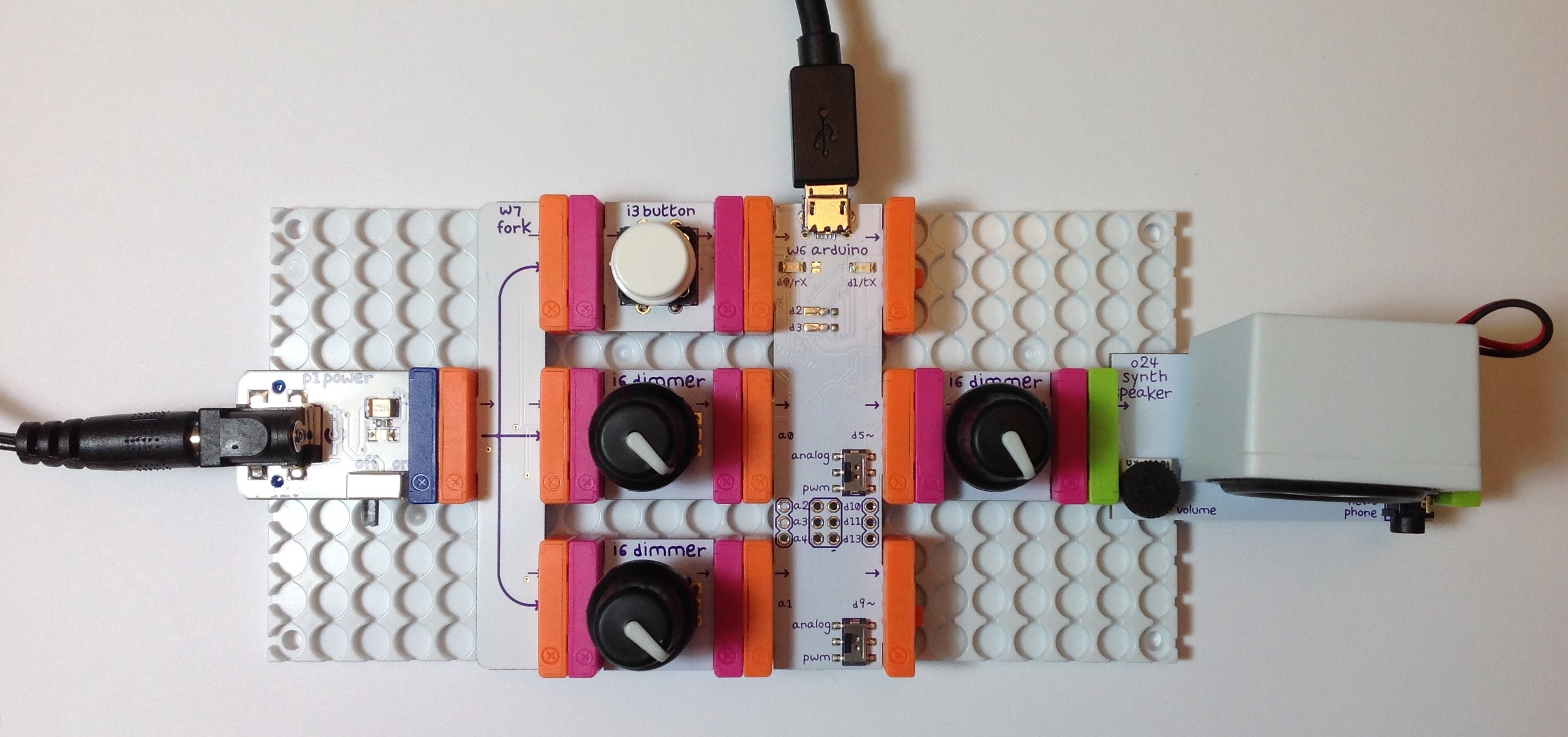
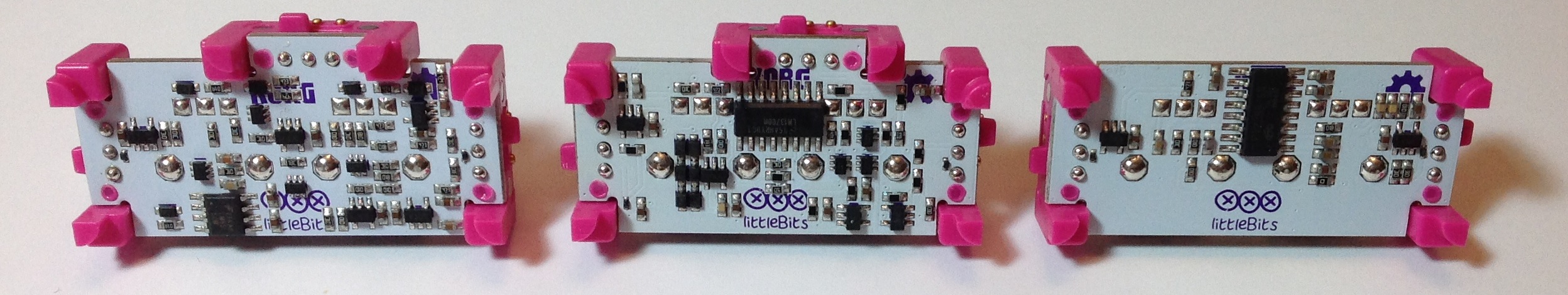
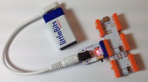
littleBits are so cute. Just in case you’ve been in an isolated cave, littleBits modules are small building blocks with magnetic “bitSnaps” at opposing ends. The magnetic bitSnaps sort the ports into inputs and outputs, and enforce an output-to-input connection rule. Each bitSnap carries the positive voltage rail, the ground rail and a signal. (Click images to get full resolution.)

dimmer_bargraph

The littleBits range covers basic digital logic and analog building blocks including audio. The Synth Kit — designed in collaboration with Korg — has perhaps done the most to promote widespread discovery and use of littleBits. The Synth Kit certainly placed littleBits in relatively non-traditional hands and sources, namely, musicians and musical instrument retailers. Before their recent bankruptcy proceedings, one could find individual ‘Bits in Radio Shack stores.

According to the manager of a local Radio Shack, the littleBits suffered a very high theft rate. Shame on anyone who unlawfully filched these!

Most retailers today (like Barnes and Noble bookstores) sell littleBits kits. The kits make it easier for people to get started and it reduces the number of separate SKUs at point-of-sale. With Radio Shack’s reorganization, these days, it is more difficult to buy individual modules a la carte. The littleBits on-line shop carries the full range, of course. Still, one rarely finds ‘Bits or kits at a discount.

The kits are also a little less easy to steal although a Barnes and Noble shopkeeper acknowledged high theft potential, too. Stop stealing!

One reason why people may feel entitled to boost littleBits with sticky fingers is their perceived expense. An LED at $7.95 may seem grossly overpriced. However, each individual module has at least two bitSnaps and there is value-added design and electronics on board. The LED module, for example, has a voltage protected input and a driver. In fact, all signals in the littleBits series are driven and normalized; that’s what makes them special. If all you want is a naked LED with two leads, then by all means pass up littleBits and try something else!

Signal standardization is what makes littleBits what they are. littleBits are very close to the plug-and-play electronic LEGO™ blocks that educators have wanted for a zillion years.

I decided to forego prepackaged kits and buy a la carte. The kits usually have modules which I probably won’t use and it just seems like a waste to buy them. That includes the Synth Kit, too. (Are you surprised?) I don’t have any interest in the tiny keyboard or the sequencer. I’m not that interested in the oscillators for that matter. I want to drive my synth and other experiments with Arduino. Thus, the only kit that I have purchased is the Arduino Coding Kit. Everything in this kit is quite useable with the exception of the servo module. (Although a Neil Young Whizzer would be a unique project!)

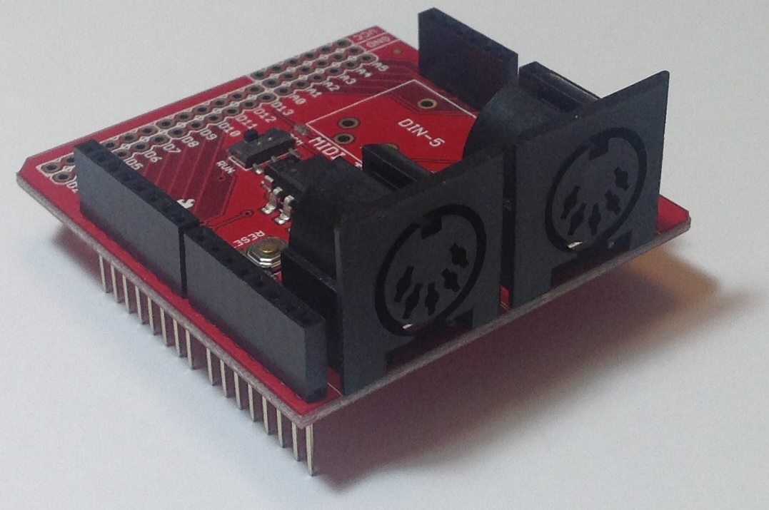
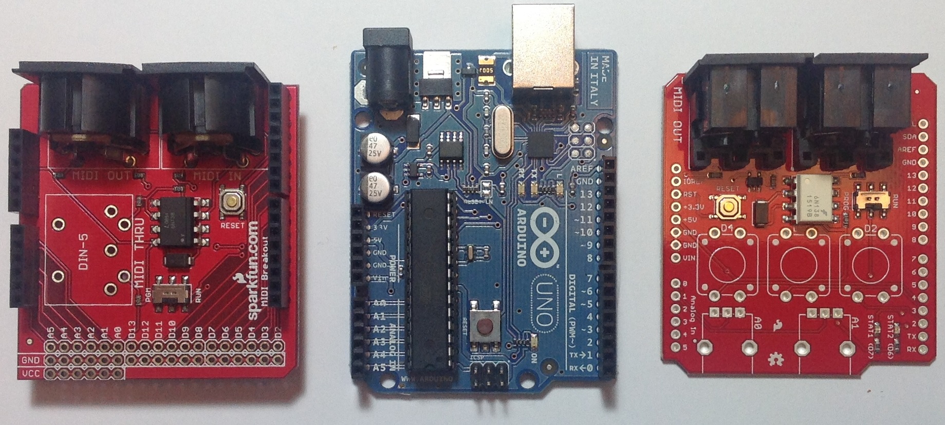
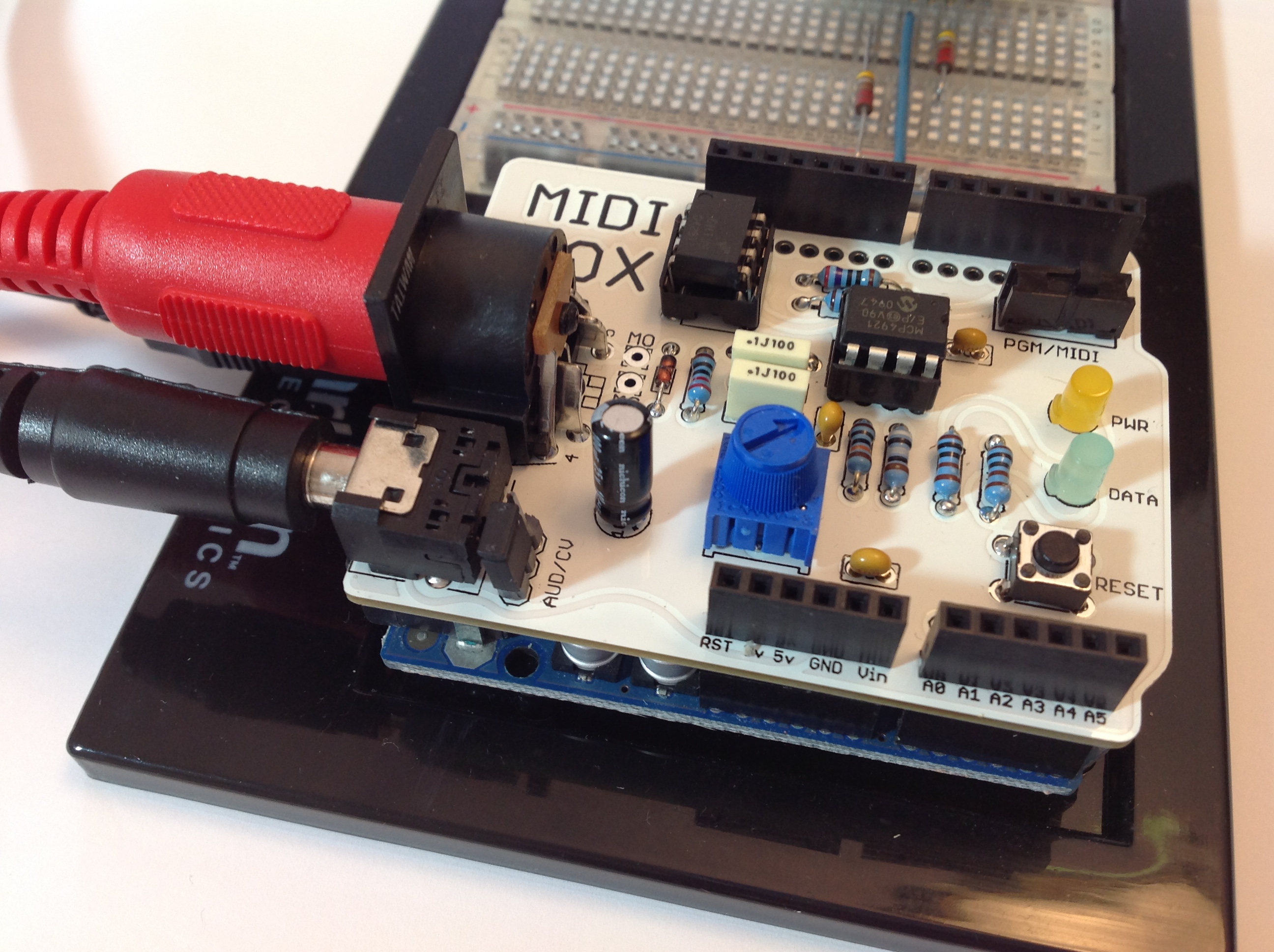
The littleBits Arduino board is a good example of value-added engineering. Sure, the Arduino ‘Bit doesn’t provide all of the ins and outs of a stock Arduino UNO, for example. However, the bitSnap signals are standardized with protection on the inputs and (switchable) low pass filters on the PWM outputs. The serial transmit (TX) and receive (RX) signals are made available through bitSnaps, making MIDI IN and OUT a future possibility. Programming is supported through either USB or ICSP. You’ll need to add header pins for ICSP, but if you’re using ICSP, you already ride tall in the saddle.

arduino_battery

I intend to whip up MIDI IN and MIDI OUT circuits using PROTO modules. I thought long and hard about the options. The Hardware Development Kit contains two PROTO modules, one PERF module and 12 bitSnaps (6 male, 6 female). I am not a fan of pad-per-hole perf board, so the PERF module is not that attractive to me. I much prefer “DIP style” prototyping boards that accomodate full size, through hole DIP ICs. This is sooooo much easier to solder. For similar reasons, I’m not sure that I want to fiddle around crafting circuit boards to conform to the bitSnaps. Overall, I will probably buy two PROTO modules a la carte.

The littleBits web site is a little sketchy on certain vital details:

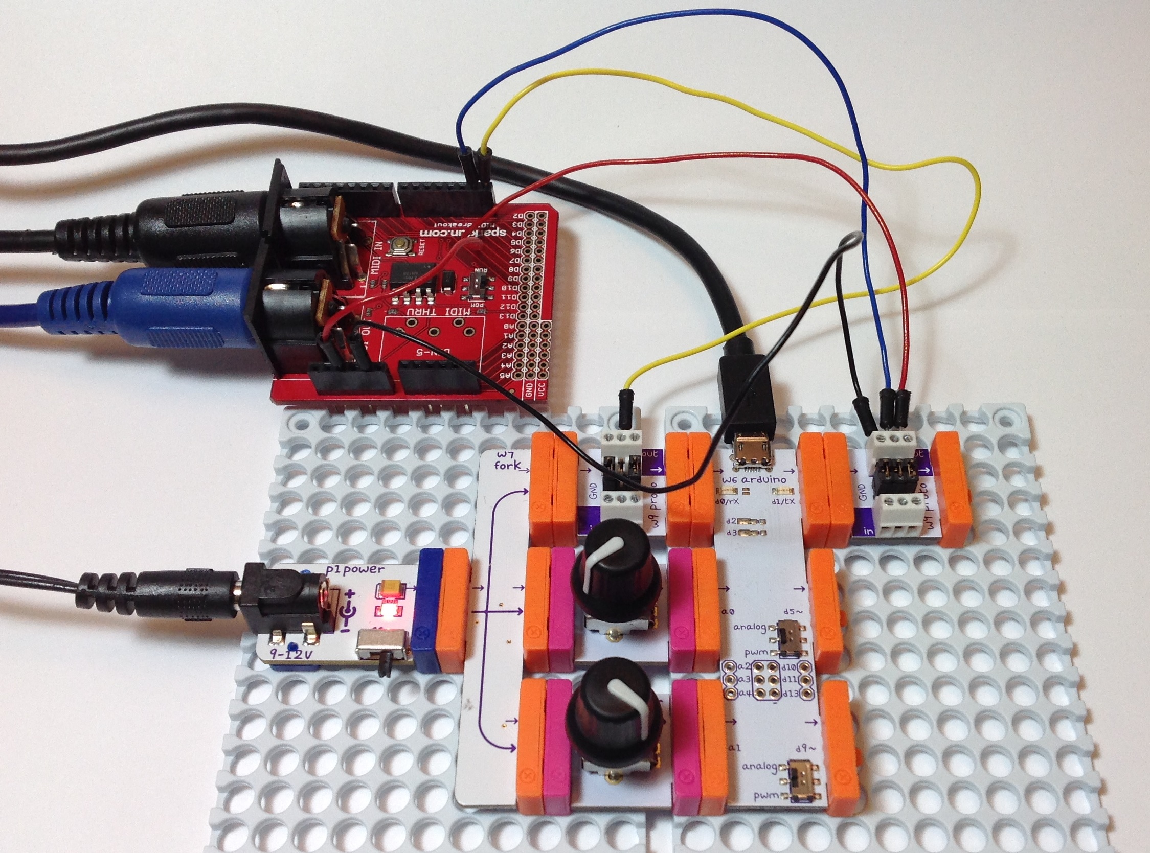
  • The Arduino board USB port is a micro USB port.
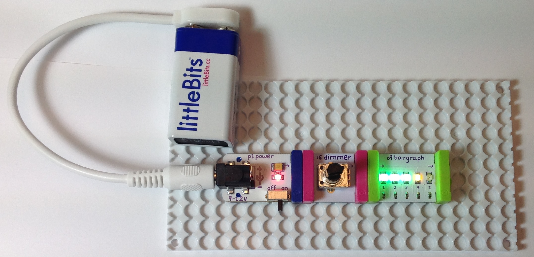
  • The power module can be driven by a 9V, center positive, 2.1mm power adapter — the same as an Arduino UNO.
  • The power module can drive any input bitSnap (any port in a storm).
  • The Arduino IDE should be configured for the Leonardo board.

I don’t like hunting around for this kind of information and I especially do not want to watch videos to find it! In fact this information should be printed on the plastic purple baggy containing the Arduino board. (Also, the link to Arduino sketches on the current baggy is dead.)

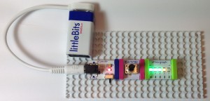
Thank goodness that the Arduino Development Kit comes with two mounting boards. A mounting board holds a littleBits circuit in place and makes connections reliable. I whipped together a simple circuit without using a mounting board and the relatively heavy adapter cable kept pulling the power module away from the other boards. The bitSnap magnets are simply not that big and strong. Programming and using an Arduino module without a mounting board would be a nightmare.

So far, a favorable, somewhat vanilla review. Here’s a bit of my own value-added as a computer science educator.

When I first powered up the pulse module — a 555 timer-based circuit that generates a regular stream of digital pulses — I didn’t necessarily see a clock. I saw a token generator. I thought, “Given the current design of the logic elements, wouldn’t it be neat to build and visualize a one-hot state machine (controller)?” If each latch module had a built-in LED showing the state of the latch, this application would be a natural for littleBits.

Even better, why not bag synchronous control altogether and go asynchronous, self-timed?

Ivan E. Sutherland, Turing Award paper, Communications of the ACM, Volume 32, Number 6, June 1989, pages 720-738. And don’t forget everything written by Chuck Seitz, too!

This immediately raises the question of what we want students to learn from their experience with littleBits. I want students to learn that:

Electronic systems are inherently parallel.

Students need to be exposed to concurrency and parallelism before their minds are corrupted by the sequential, synchronous paradigm in conventional programming languages.

The other question that pops up is scalability. littleBits logic elements currently operate at the bit level. However, I’d love to have modules at the bus level such that students could build their own CPUs, GPUs, whatever. Plug-and-play busses are a tougher design challenge electrically and mechanically. One possible solution is to transmit data words serially from module to module. Pass the word size along with the data in order to simulate any (reasonable) bus width. littleBits could then keep the current bitSnap form factor.

Finally, I would like to mention the module technology that gave me a start in digital electronics: DEC Register Transfer Modules, also called the “PDP-16” or “RTMs.” RTMs use a flowchart-like notation for control design. This approach opened a whole world to me including ISP, Petri Nets and eventually dataflow computing. Most importantly, RTMs taught my 19 year-old mind that computation is fundamentally parallel and we should design for and exploit concurrency right from the get-go. Nico Habermann, God bless him, did the same in the sophomore programming course at C-MU. This point of view influenced my entire professional life!

If you would like to know more about RTMs, then read “Designing Computers and Digital Systems Using PDP-16 Register Transfer Modules,” by C. Gordon Bell, John Grason and Allen Newell, 1972. I was one of the first guinea pigs to use RTMs in the computer design course taught by John Grason. Thanks, John!

See also “The Description and Use of Register-Transfer Modules,” C. Gordon Bell, J.L. Eggbert, J. Grason, and P. Williams, IEEE Transactions on Computers, Volume C-21, Number 5, May 1972, pages 495-500.

MidiVOX: An appreciation and review

They just don’t make ’em like they used to. In the case, of the Narbotic Instruments MidiVOX shield for Arduino, I really mean it!

The MidiVox is a bit of a blast from the past as Narbotic no longer manufacture and sell the MidiVOX shield kit. Major bummer. Luckily, I purchased one of these little gems from the MakerShed when the shields were available a few years ago. Narbotic kindly maintain the design information and code on their Web site.

To me, the MidiVox is a most logical combination of a MIDI IN port and a 12-bit digital-to-analog converter (DAC). The MIDI port incorporates a 6N138 optocoupler for electrical isolation and a 5-pin DIN connector. The port is connected through a “PGM/MIDI” switch to Arduino digital pin D0, also known as the serial receive (RX) pin. The PGM position connects the serial pin the usual way in order to download to the Arduino. The MIDI position connects the Arduino serial RX pin to the MIDI IN circuitry. The switch component is robust and is easily accessible when the MidiVOX is on top of the Arduino and/or other shields.

The 12-bit DAC is a Microchip Technology MCP4921. This DAC is used in several other audio shield designs including the Adafruit Wave Shield and the Nootropic Design Audio Hacker Kit. The MCP4921 connects to the Arduino SPI port through digital pins D13 (SCK), D11 (MOSI), and D9 (chip select/slave select). Conventional practice recommends using D10 as slave select (SS), but it isn’t a big deal to use D9 instead as this is mainly a software issue. Slave Select (called “chip select” in the MCP4921) chooses and enables communication with the slave device. This capability is essential when more than one device is connected to the same SPI interface as in the case of the Nootropic Audio Hacker shield.

Although it seems like a no-brainer to connect all SPI devices to the Arduino SPI pins, the Adafruit Wave Shield does not follow this approach. It connects the SD card interface to the SPI pins, but connects its MCP4921 to three ordinary digital pins. The Wave shield software bit-bangs the digital pins to transfer data to its DAC. I’m not a fan of this approach, preferring to use standard libraries instead of possibly buggy, poorly documented bit twiddling code.

The MidiVOX shield implements a 2-stage, passive filter following the DAC output. The MidiVOX sends a mono signal through an on-board trim pot into a 3.5mm audio output jack. Trim pots are usually rated for a relatively small number of operating cycles, so it’s best to set this level once and make volume adjusts at an external mixer, preamp, or whatever.

The MidiVOX shield provides a DATA LED controlled by digital pin D7. The shield also has a RESET button (momentary contact switch) connected to digital pin D6. This button is ACTIVE LOW, meaning that the button pulls D6 to ground when it is pressed. Therefore, the pin mode should be configured as INPUT_PULLUP such that D6 is pulled up internally when the button is not pressed (i.e., the momentary contact switch is open).

Construction was easy. The resistors have five color bands, but don’t let this throw you off. The construction directions give the correct color code and you can (and should!) always check resistor values with a meter before insertion and soldering. I replaced the basic header pins with “stackable headers” (two 8-pin and two 6-pin). Stackable headers provide a way to make easy external connections to the shield stack from a breadboard, etc.

The completed board is shown in the photo below. The MidiVOX is stacked on an Arduino UNO with the USB, audio and MIDI cables, and is ready to go.

MidiVox

I wrote a diagnostic sketch to check out the different parts of the MidiVOX. I wish manufacturers would provide check-out sketches instead of relying on somebody’s possibly flaky application sketch for smoke testing. If something is busted, it’s important to find it early through a directed test that isolates the failure. Fortunately, everything checked out OK the first time!

The MidiVOX diagnostic program is an Arduino sketch to check out parts of a Narbotic Instruments MidiVOX shield. Rename the “loop” functions and rebuild in order to test a particular section of the shield.

Since the MidiVOX is discontinued, we’re all out of luck if we want to get (another) one. However, I strongly recommend studying the MidiVOX design. When I first got started with Arduino and MIDI, I borrowed the MIDI IN circuitry and the low pass filter design. These are simple, solid circuits and are good basic building blocks for other designs and applications.

Where to next? My dream is to build a low-cost 60s combo organ with the era-appropriate look and sound. The organ would look like a Vox Continental with a Z-shaped chrome stand and bright red Tolex covering. It would sound like either a Farfisa or a Vox — nothing too nuanced with all of the drawbars or tabs turned on. I’d like to use a cheap and lightweight MIDI controller as the keyboard. The controller would drive a low-cost (Arduino-based?) sound generator. I’m hacking out a prototype using an Arduino UNO and the MidiVOX shield. More to come…