Combo organ: Top octave generator

So far, we’re taken a short trip through combo organ technology from early days in the 1960s to modern day workstation voices:

I hope you enjoyed those articles! This post fills in the middle bits — how large scale integration changed combo organ design.

Farfisa tone generation circuit

During the 60s, Vox, Farfisa and other manufacturers employed a similar approach to tone generation. Each organ contained twelve tone generation boards one for each semi-tone in the Western well-tempered scale. Each board implemented:

  • An oscillator to produce the a base root tone, and
  • Several (digital) dividers to derive the ancilliary tones one or more octaves below the root tone.

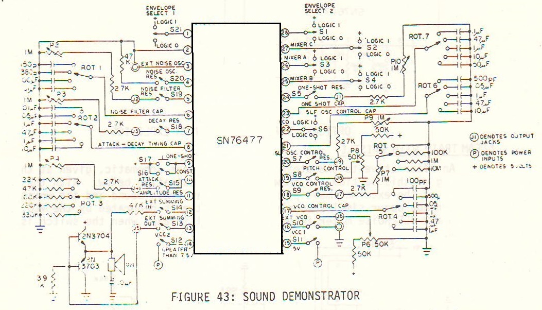
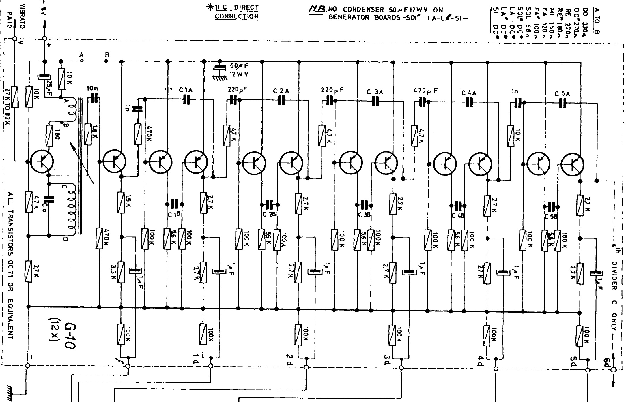
Vox, Farfisa, and so on used discrete components (transistors, resistors, capacitors, etc.) to implement the oscillator and dividers. These boards were dense and busy with many hand-soldered joints. The Farfisa board, for example, contained 12 transistors, 40 resistors, 25 capacitors and a tunable inductor coil. Assembling, testing and debugging a board like that is quite expensive and labor intensive.

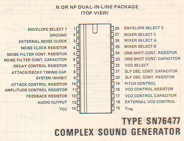
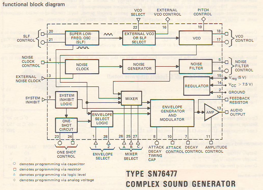
Having lived through the transition from discrete semiconductor circuits to small scale integration (SSI) and then large scale integeration (LSI), I can attest to the revolution initiated in the LSI era. (Not to mention the transition to very large scale integration!) LSI and mixed signal components enabled sound generators like the Texas Instruments SN76477 Complex Sound Generator, General Instruments AY-3-8910/8912, and other ICs — and sounds — favored by chip-tune enthusiasts.

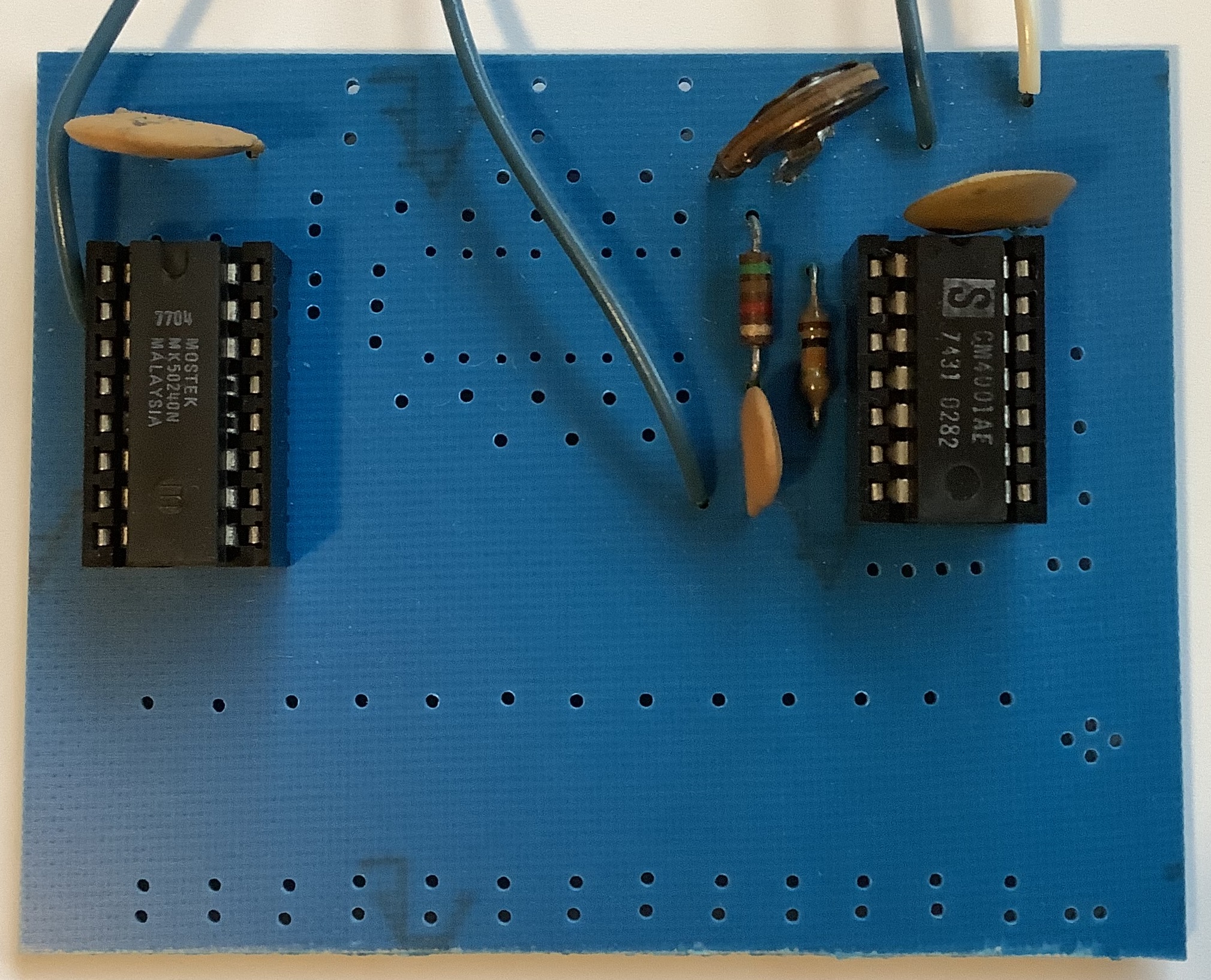
LSI revolutionized combo organ design, too. Mostek (and others) introduced top octave tone generator chips. The well-known Mostek MK50240 (PDF datasheet) has inputs for power, ground and master clock:

    Pin#  Name  Purpose 
---- ---- --------------
1 VSS Supply voltage 15V (typical) 11V (min) 16V (max)
2 Clock Clock 2000.240kHz (typical), 2500kHz (max)
3 VDD Ground

The MK50240 generates each of the high frequency root tones:

    Pin#  Note  Divisor 
---- ---- -------
16 CLow 478
4 C# 451
5 D 426
6 D# 402
7 E 379
8 F 358
9 F# 338
10 G 319
11 G# 301
12 A 284
13 A# 268
14 B 253
15 CHigh 239

The MK50240 has twelve dividers which divide the master clock frequency into the root tone frequencies.

Advantages of the MK50240 should be readily apparent! A single MK50240 replaces all twelve oscillators. Even better, the master clock can be generated from a 2000.240 kHz crystal resulting in superior temperature (pitch) stability. Old discrete circuits are notoriously temperature sensitive.

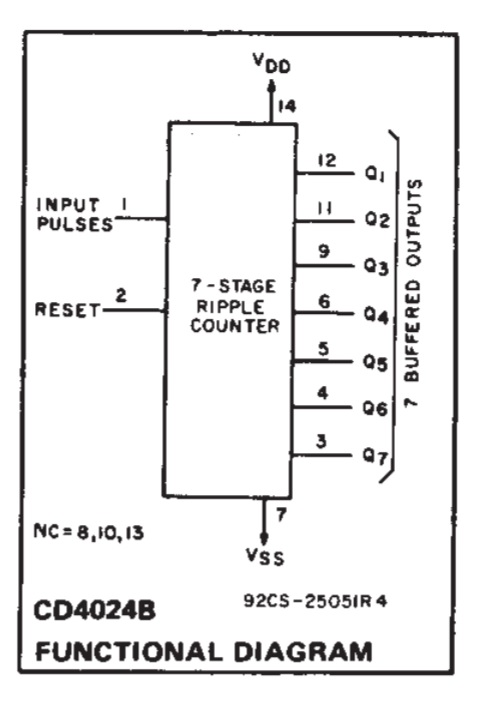
But, wait, there’s more. Thanks to digital LSI, each divider chain can be replaced by an MOS ripple counter. Consider the CMOS CD4024. (Please see the CD4024B functional diagram below.) The CD4024 is a 7-stage ripple counter that divides the incoming clock signal into seven auxilliary tones at each octave below the input frequency.

The nightmare of discrete oscillators and dividers can be replaced by a single MK50240 and 12 CD4024 ripple counters: 13 dual in-line packages (DIPs) and a handful of coupling capacitors for good measure.

Of course, one must still confront the rat’s nest of wires and signal diodes needed for key switching… To get a sense of wiring complexity, I suggest looking at the design of the vintage PAiA Stringz ‘n’ Thingz digital keyboard or PAiA Oz portable mini-organ. Yes, I assembled a Stringz ‘n’ Thingz — without too many bad solder joints, thank goodness. Organ wiring was a nightmare before microcomputer-based key switch scanning and digital control.

With LSI and micro-computers, organ builders collectively breathed a sigh of relief. Unfortunately, ease of design and manufacture came with a penalty — lack of sonic charm. Each of those old-tyme discrete oscillators were slightly out-of-tune with one another. Thus, there’s a subtle richness in the old discrete designs that is missing in full-on digital implementations.

Before leaving the MK50240 behind, I want to mention the PAiA EK-1 top octave experimenter’s kit.

PAiA EK-1 board (component side)
PAiA EK-1 board (trace side)

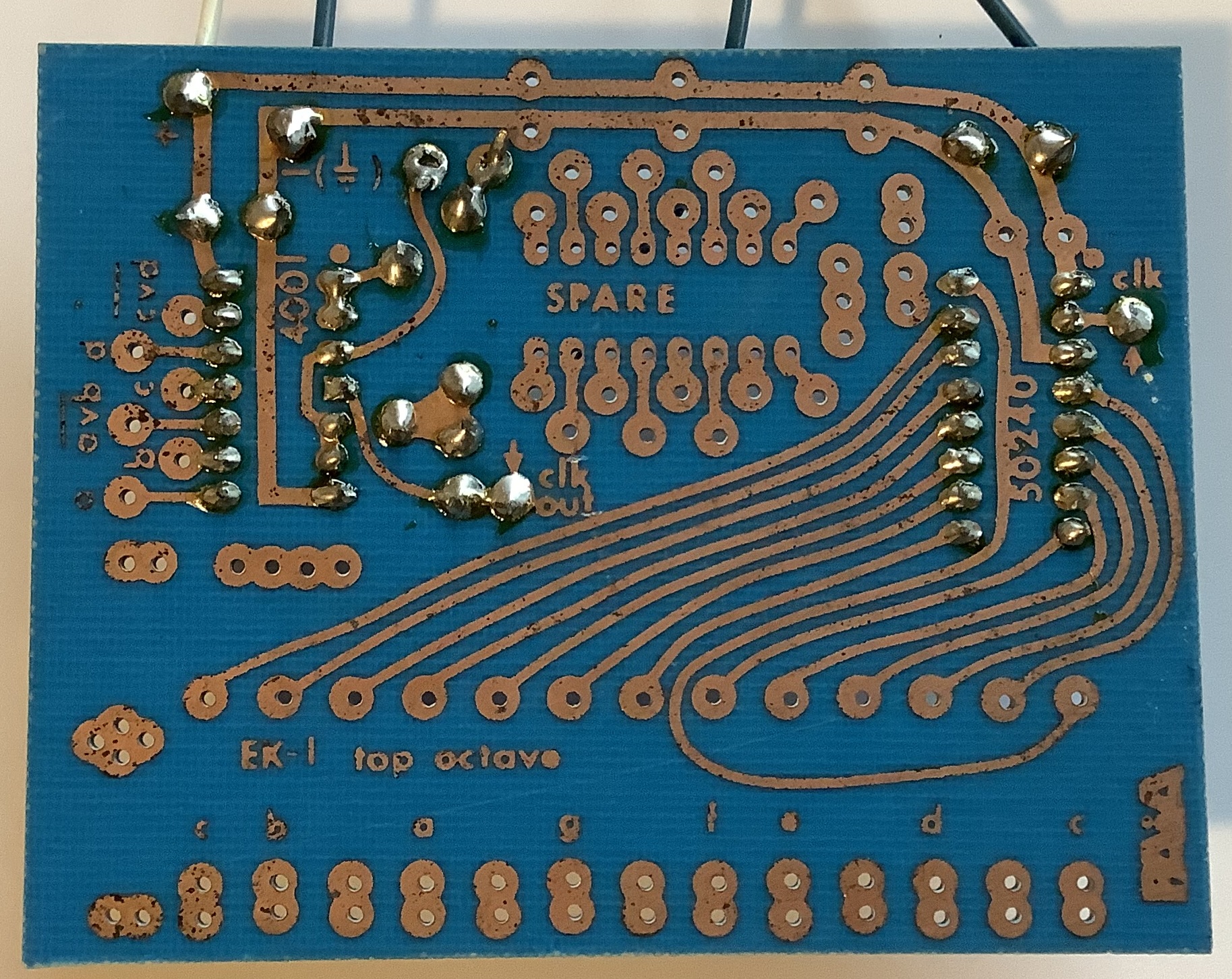
PAiA was (and is) a terrific resource for experimenters. I built several PAiA kits including the Stringz ‘n’ Thingz and the Gnome synthesizer. I also played with the PAiA EK-1 top octave experimenter’s kit. If you would like to learn more about the Mostek MK50240, check out the PAiA EK-1 instruction booklet. Shame you can’t find many MK50240s today…

Copyright © 2021 Paul J. Drongowski

Curtis Electromusic Specialties

Tom Oberheim plans to bring back the TVS-Pro in the form of the TVS Pro Special Edition. The TVS-Pro Special Edition consists of a 3-octave keyboard, sequences and two Synthesizer Expansion Modules (SEM). The two modules are flexibly assigned to the keyboard, sequencer, etc. Designed by Tom Oberheim and manufactured by Marion Systems. Gordon Reid reviewed the original Two Voice Pro in Sound on Sound (July 2016).

To my ear, Tom Oberheim, OB-Xa and Curtis Electromusic Specialties (CES) are synonymous. And that brings me to today’s offerings from CES circa 1981.

OK, OK, Dave Smith, Prophet-5, Pro-One, and Curtis Electromusic Specialties are synonymous, too. Pro-One (CEM 3340, CEM 3310, CEM 3320) — wish I had that one back… 🙂

Doug Curtis was an analog synthesis circuit genius and founded Curtis Electromusic Specialties (CES) in 1979. Doug’s fertile mind and CES produced what is arguably the most successful line of commercial integrated circuits (IC) for analog synthesis.

I’m happy to share my collection of CES brochures, data sheets and schematics, all in PDF:

Unlike data sheets posted at some other sites, these data sheets are complete (not just the first two pages). The preliminary data sheets are hand-drawn — now that’s preliminary!

The SynthSource newsletter contains an interview with Tom Oberheim titled “Giving the musician more for his money.” Doug’s chips made Tom’s successful OB-X synths (OB-X and OB-Xa) physically and economically feasible. The OB-Xa used the entire CES chip line: 3310, 3320, 3330, 3340 and 3360.

The newsletter also announces the CEV 3301 Evaluation Board hosting one each of the CEM 3310, CEM 3320, CEM 3330 and CEM 3340. At that time, PAiA Electronics sold both CES chips and the CEV 3301 Evaluation Board. I bought ’em all. 🙂 The CEV 3301 PDF covers design, construction details, board layout and schematics. I’ve posted pictures (below) of the unpopulated CEV 3301.

Curtis Electromusic CEV 3301 Evaluation board (trace side)
Curtis Electromusic CEV 3301 Evaluation board (component side)

Have fun and stay healthy!

Copyright © 2021 Paul J. Drongowski

E-mu Systems and SSM ICs

E-mu Systems and Solid State Micro Technology for Music (SSM) were pioneers in analog synthesis. E-mu Systems was founded in 1971 by Dave Rossum, Steve Gabriel and Jim Ketcham. Solid State Music Technology was founded by Ron Dow and John Burgoon in 1974. E-mu, of course, is renown for its ground-breaking Emulator keyboard.

E-mu and SSM developed several integrated circuits (IC) for analog synthesis. Also in that era (1978), Curtis Electromusic Specialties (CES) introduced their own line of analog synthesis chips.

In 1978, I was finishing up my stint in Silicon Valley and heading to grad school at the University of Utah — as far east as my meager savings could take me. Little did I know that Ercolino Ferretti at the U was investigating computer music and I would soon enjoy his expertise and banter!

Nonetheless, I was interested in building my own synth gear and I wrote to E-mu/SSM for information about the SSM demonstrator board and their chips. Here are three PDFs covering the E-mu/SSM offerings in 1978:

Check out these prices!

  • SSM 2010 VCA: $12.50
  • SSM 2020 DVCA: $7.50
  • SSM 2030 VCO: $10.00
  • SSM 2040 VCF: $10.00
  • SSM 2050 TG: $7.50

Good luck finding E-mu/SSM chips today. They’re worth their weight in gold.

Copyright © 2021 Paul J. Drongowski

SN76477 Complex Sound Generator

Things are going to take a vintage turn during the next few weeks. I’m knocking out a few 60’s backing tracks, returning to classic combo organ sounds. As a teen, I owned and played a Farfisa Mini Compact Deluxe. As a neophyte engineer, I was also interested in rolling my own gear — a great entry-way to audio electronics. [Not drugs.]

Thanks to our move, I uncovered, literally, a small number of brochures and data sheets from the 70’s and 80’s era. Today’s subject is the Texas Instruments SN76477 Complex Sound Generator.

TI SN76477 Complex Sound Generator pin out

The SN76477 was an all purpose, mixed signal (digital+analog) noise maker, appearing in games, toys and other mass market consumer electronics. Its temperature stability was none-to-good, making it a poor choice for musical instrument design. It excels, however, at cheesy 1980’s sound effects.

TI SN76477 Complex Sound Generator block diagram

I built the SN76477 sound demonstration circuit (below) into a “busy box” for our son. Unfortunately, the busy box and the SN76477 is lost and gone. Only the data sheets and application notes remain in its place. If you find an SN76477, it’s most likely a “pull” from an old toy and probably not new old stock (NOS).

TI SN76477 Sound demonstration circuit

Here are links to the SN76477 data sheets and application guide. All of the files are PDF.

I apologize for the yellow pages, but we are talking true vintage! The sound development system schematic is brittle and requires careful handling.

TI wrote a very compresensive SN76477 guide, so there isn’t too much point in detailing the SN76477 here. If you’re going to experiment with the SN76477, the TI guide is a must-read. The guide describes a few of the internal circuits as well as sample application circuits.

Copyright © 2021 Paul J. Drongowski